
Service Manual
Page 1
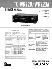
..., 50/60Hz (AEP model) 120, 220, 240, 50/60Hz (E model) Power consumption 33 watts Dimensions Approx. 430 X135 X 285mm (w/h/d) (17 X53/8 X111/4 inches) including projecting parts and controls Weight Approx. 5kg (11 lbs 1 oz) (WR720) Approx. 4.6kg (10 lbs 3 oz) (WR720A) Supplied accessories Audio connecting cord (2) Remote commander (RM-900W) (E model only) Conversion adaptor (E model only) Design and specifications subject to change without notice. STEREO CASSETTE DECK SONY trM;),T.
..., 50/60Hz (AEP model) 120, 220, 240, 50/60Hz (E model) Power consumption 33 watts Dimensions Approx. 430 X135 X 285mm (w/h/d) (17 X53/8 X111/4 inches) including projecting parts and controls Weight Approx. 5kg (11 lbs 1 oz) (WR720) Approx. 4.6kg (10 lbs 3 oz) (WR720A) Supplied accessories Audio connecting cord (2) Remote commander (RM-900W) (E model only) Conversion adaptor (E model only) Design and specifications subject to change without notice. STEREO CASSETTE DECK SONY trM;),T.
Service Manual
Page 2
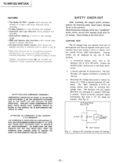
... Precision 245 digital multimeter is suitable. A) To Exposed Metal Parts on Set 0.15µF 1.5kf2 AC voltmeter (0.751/1 = Earth Ground Fig. TC-WR720/WR720A FEATURES • The Dolby HX PRO* system which improves the linearity of a tape's high-range response during recording. • A relay function for long recording and playback. • Automatic tape type detection during playback and recording. • Auto-synchro...
... Precision 245 digital multimeter is suitable. A) To Exposed Metal Parts on Set 0.15µF 1.5kf2 AC voltmeter (0.751/1 = Earth Ground Fig. TC-WR720/WR720A FEATURES • The Dolby HX PRO* system which improves the linearity of a tape's high-range response during recording. • A relay function for long recording and playback. • Automatic tape type detection during playback and recording. • Auto-synchro...

Service Manual
Page 3
... Title Page 1. Printed Wiring Boards -Main Section- 14 5-4. Printed Wiring Boards -Panel Section- 28 6. Mechanism Deck (WR720) 6 2-5. EXPLODED VIEWS 6-1. Circuit Boards Location 12 5-2. Mechanism Section-2 34 7. Front Panel (WR720A) 5 2-2. Schematic Diagram -System Control Section- .23 5-6. MECHANICAL ADJUSTMENTS 8 4. Front Panel Section (WR720A) 31 6-3. -MODEL IDENTIFICATION(Specification Label) TC-W720: AEP, WG (West Germany) model SONY® MODEL NO. GENERAL 1-1. ELECTRICAL ADJUSTMENTS 8 5. Schematic Diagram -Audio/Power Section- 19 5-5.
... Title Page 1. Printed Wiring Boards -Main Section- 14 5-4. Printed Wiring Boards -Panel Section- 28 6. Mechanism Deck (WR720) 6 2-5. EXPLODED VIEWS 6-1. Circuit Boards Location 12 5-2. Mechanism Section-2 34 7. Front Panel (WR720A) 5 2-2. Schematic Diagram -System Control Section- .23 5-6. MECHANICAL ADJUSTMENTS 8 4. Front Panel Section (WR720A) 31 6-3. -MODEL IDENTIFICATION(Specification Label) TC-W720: AEP, WG (West Germany) model SONY® MODEL NO. GENERAL 1-1. ELECTRICAL ADJUSTMENTS 8 5. Schematic Diagram -Audio/Power Section- 19 5-5.
Service Manual
Page 4
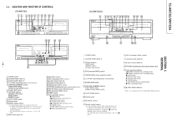
... or receiver it it has the mark and cassette deck control capability Any optional Sony remote commander with : - A remote commander that came with - Any optional Sony remote commander von) the 1A mark .111 BIAS control (deck B) 121 BALANCE control REC (recording) LEVEL control eject button (deck B) 15iCassette holder (deck B) Headphones LEVEL control 17 PHONES (headphones) jack (stereo phone jack) NR (Dolby noise reduction)switch 19 DIR (direction) MODE switch i0) TIMER switch Tape operation buttons • (stop) button .4.4 (leftward fast winding) button (reverse play) button pi...
... or receiver it it has the mark and cassette deck control capability Any optional Sony remote commander with : - A remote commander that came with - Any optional Sony remote commander von) the 1A mark .111 BIAS control (deck B) 121 BALANCE control REC (recording) LEVEL control eject button (deck B) 15iCassette holder (deck B) Headphones LEVEL control 17 PHONES (headphones) jack (stereo phone jack) NR (Dolby noise reduction)switch 19 DIR (direction) MODE switch i0) TIMER switch Tape operation buttons • (stop) button .4.4 (leftward fast winding) button (reverse play) button pi...
Service Manual
Page 8
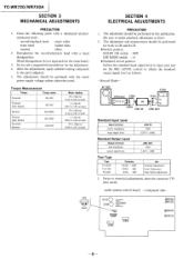
... input jack and set 6000 LINE IN 47k0 LINE OUT Standard Input Level Input terminal source impedance input signal level LINE IN 10kil 0.25V (-10dB) Standard Output Level Output terminal load impedance output signal level LINE OUT 47kS2 0.44V (-5dB) Test Tape Tape P-4-A100 P-4-L300 WS-48B Contents 10kHz, -10dB 315Hz, 0dB 3kHz, 0dB Use Azimuth Adjustment Level Adjustment Tape Speed Adjustment 3. TC-WR720/WR720A SECTION 3 MECHANICAL ADJUSTMENTS PRECAUTION 1. Do not use a magnetized screwdriver for both L-CH and R-CH. • Switch position DOLBY...
... input jack and set 6000 LINE IN 47k0 LINE OUT Standard Input Level Input terminal source impedance input signal level LINE IN 10kil 0.25V (-10dB) Standard Output Level Output terminal load impedance output signal level LINE OUT 47kS2 0.44V (-5dB) Test Tape Tape P-4-A100 P-4-L300 WS-48B Contents 10kHz, -10dB 315Hz, 0dB 3kHz, 0dB Use Azimuth Adjustment Level Adjustment Tape Speed Adjustment 3. TC-WR720/WR720A SECTION 3 MECHANICAL ADJUSTMENTS PRECAUTION 1. Do not use a magnetized screwdriver for both L-CH and R-CH. • Switch position DOLBY...

Service Manual
Page 9
...;30Hz on both of deck A and deck B. 7. Adjustment Location : MD (C) board (deck A, deck B) O forward side reverse side adjustment screws -9- Playback Mode test tape P-4-A100 (10kHz, -10dB) L CH set LINE OUT (high speed adjustment) 1. Procedure: -Forward Playback Mode- Keep on pressing the SYNCHRO DUBBING NORM SPEED switch. 6. Reverse Playback Mode test tape P-4-A100 (10kHz, -10dB) 47k0 VTVM set LINE OUT 2. L-CH peak output level within 1dB within adjustment limits of 6,000...
...;30Hz on both of deck A and deck B. 7. Adjustment Location : MD (C) board (deck A, deck B) O forward side reverse side adjustment screws -9- Playback Mode test tape P-4-A100 (10kHz, -10dB) L CH set LINE OUT (high speed adjustment) 1. Procedure: -Forward Playback Mode- Keep on pressing the SYNCHRO DUBBING NORM SPEED switch. 6. Reverse Playback Mode test tape P-4-A100 (10kHz, -10dB) 47k0 VTVM set LINE OUT 2. L-CH peak output level within 1dB within adjustment limits of 6,000...

Service Manual
Page 10
... channels : within adjustment limits below relative to the 315Hz output. 4. Procedure: LINE IN no signal blank tape CS-413 1-1 digital voltmeter set 47kO VTVM !O / „, LINE OUT (deck A) 3. Set RV0391 (L-CH) and RV0491 (R-CH) to page 8.) Procedure : 1. Adjustment Location : HX-PRO board (A) (deck A), HX-PRO board (B) (deck B) Record Bias Adjustment DECK A DECK B Setting : REC LEVEL control: standard record position (Refer to mechanical center. 3. Record Mode AF OSC attenuator 2. Playback Level Adjustment Procedure: -Forward Playback Mode- Connect...
... channels : within adjustment limits below relative to the 315Hz output. 4. Procedure: LINE IN no signal blank tape CS-413 1-1 digital voltmeter set 47kO VTVM !O / „, LINE OUT (deck A) 3. Set RV0391 (L-CH) and RV0491 (R-CH) to page 8.) Procedure : 1. Adjustment Location : HX-PRO board (A) (deck A), HX-PRO board (B) (deck B) Record Bias Adjustment DECK A DECK B Setting : REC LEVEL control: standard record position (Refer to mechanical center. 3. Record Mode AF OSC attenuator 2. Playback Level Adjustment Procedure: -Forward Playback Mode- Connect...

Service Manual
Page 11
... the 315Hz output : 0±0.5dB (0.732 to 0.82IV) Adjustment Location : audio system control board Record Level Adjustment DECK A DECK B Setting : REC LEVEL control: standard record position (Refer to 46mV) Adjustment Location : audio system control board Note : After adjustment, open the connector TP1. -Adjustment Parts Location Diagrams- MD (C) board (deck A, deck B) 1 n RV72 TAPE SPEED (HIGH) RV71 TAPE SPEED (NORMAL) RV21 PLAYBACK { (R-CH) LEVEL RV11 (L-CH) HX-PRO board (A) (deck A), HX-PRO board (B) (deck B) 5 4 3 2 1 TP0691 (deck A) 000 0 0 TP691 (deck B) 0 0 T0391 (deck A) T391...
... the 315Hz output : 0±0.5dB (0.732 to 0.82IV) Adjustment Location : audio system control board Record Level Adjustment DECK A DECK B Setting : REC LEVEL control: standard record position (Refer to 46mV) Adjustment Location : audio system control board Note : After adjustment, open the connector TP1. -Adjustment Parts Location Diagrams- MD (C) board (deck A, deck B) 1 n RV72 TAPE SPEED (HIGH) RV71 TAPE SPEED (NORMAL) RV21 PLAYBACK { (R-CH) LEVEL RV11 (L-CH) HX-PRO board (A) (deck A), HX-PRO board (B) (deck B) 5 4 3 2 1 TP0691 (deck A) 000 0 0 TP691 (deck B) 0 0 T0391 (deck A) T391...
Service Manual
Page 14
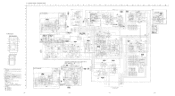
... --4 80492 1506 C9403 io 0 • CN0691 (DECK A) CRP0691 (A047.5V) 3595 510 184 R0902 - 511901 BALANCE REC LEVEL I 7 W1 IOU 0 IC601 11/21 95216AP CN505 %00274I 5 J50 1 _J PHONES _ _ ( 5-4. WR720A IC601 HEADPHONE AMP J301 -LINE IN cL) -- SCHEMATIC DIAGRAM -AUDIO/POWER SECTION- 1 2 3 4 5 6 7 8 9 10 11 12 13 14 15 I 16 I 17 18 19 20 I - 1: adjustment for electrolytics and tantalums. • All...
... --4 80492 1506 C9403 io 0 • CN0691 (DECK A) CRP0691 (A047.5V) 3595 510 184 R0902 - 511901 BALANCE REC LEVEL I 7 W1 IOU 0 IC601 11/21 95216AP CN505 %00274I 5 J50 1 _J PHONES _ _ ( 5-4. WR720A IC601 HEADPHONE AMP J301 -LINE IN cL) -- SCHEMATIC DIAGRAM -AUDIO/POWER SECTION- 1 2 3 4 5 6 7 8 9 10 11 12 13 14 15 I 16 I 17 18 19 20 I - 1: adjustment for electrolytics and tantalums. • All...

Service Manual
Page 15
... SWITCH ETAL -7.4 DECK B • :-5.i 705 -0.4 DECK B • 1- 2.9 DECK B :52 • 7 6 I6 12 82 XI 000,1 X0 X3 A iC806 -7 4 MC I 11 A B C D F G H J K L M N O WR720A FL90, FLUORESCENT INDICATOR TUBE PLAY HOC NORM HIGH AUTO PAUSE BLANK SKIP - pF: µµF 50WV or less are not indicated except for repair. • Voltage is Is 1 `, ,) . . . and 14/ W or less unless otherwise • • :: internal component. SCHEMATIC DIAGRAM...
... SWITCH ETAL -7.4 DECK B • :-5.i 705 -0.4 DECK B • 1- 2.9 DECK B :52 • 7 6 I6 12 82 XI 000,1 X0 X3 A iC806 -7 4 MC I 11 A B C D F G H J K L M N O WR720A FL90, FLUORESCENT INDICATOR TUBE PLAY HOC NORM HIGH AUTO PAUSE BLANK SKIP - pF: µµF 50WV or less are not indicated except for repair. • Voltage is Is 1 `, ,) . . . and 14/ W or less unless otherwise • • :: internal component. SCHEMATIC DIAGRAM...

Service Manual
Page 16
... specified. • : internal component. • Voltage is dc with a VOM (Input Impedance 10M 4). M N -27- 5-6. tion tolerances. Voltage variations may be noted due to ground under no mark: POWER ON • Voltages are taken with respect to normal produc- SCHEMATIC DIAGRAM -PANEL SECTION- 1 I 2 I 3 I 4 I 5 6 7 8 A B C D E F G H J K Note: • All capacitors are in µF unless otherwise noted. no -signal conditions. WR720 IC901 FL...
... specified. • : internal component. • Voltage is dc with a VOM (Input Impedance 10M 4). M N -27- 5-6. tion tolerances. Voltage variations may be noted due to ground under no mark: POWER ON • Voltages are taken with respect to normal produc- SCHEMATIC DIAGRAM -PANEL SECTION- 1 I 2 I 3 I 4 I 5 6 7 8 A B C D E F G H J K Note: • All capacitors are in µF unless otherwise noted. no -signal conditions. WR720 IC901 FL...

Service Manual
Page 17
...). . . .MOUNTED PCB, AUDIO SYSTEM CONTROL 902 *1-533-213-31 HOLDER, FUSE 903 11-551-188-XX (E). . . .CORD, POWER 904 1.1-551-506-XX (US, Canadian). . . .CORD, POWER 905 11-555-795-00 (AEP, WG). . . .CORD, POWER, EULO PLUG F701 11-532-259-00 (AEP, WG, E). . . .FUSE, TIME-LAG (T1.6A/250V) F701 11-532-742-11 (US, Canadian). . . . Replace only with part number suffix -XX and...
...). . . .MOUNTED PCB, AUDIO SYSTEM CONTROL 902 *1-533-213-31 HOLDER, FUSE 903 11-551-188-XX (E). . . .CORD, POWER 904 1.1-551-506-XX (US, Canadian). . . .CORD, POWER 905 11-555-795-00 (AEP, WG). . . .CORD, POWER, EULO PLUG F701 11-532-259-00 (AEP, WG, E). . . .FUSE, TIME-LAG (T1.6A/250V) F701 11-532-742-11 (US, Canadian). . . . Replace only with part number suffix -XX and...

Service Manual
Page 18
...I 52 .f" X58 AC 54 55 51 908 E 57 59 60 72 73 J5O1 S87 913 (DECK B) Ref.No Part No. Description Remarks 70 *3-682-419-21 HOLDER, P.C.B 71 3-354-932-01 BUTTON (POWER) 72 *4-933-135-01 RING (DIA. 58A), ORNAMENTAL 73 7-685-134-19 SCREW (+ PTPWH)(2....-11 WIRE, FLAT TYPE (9 CORE) FL901 1-519-593-11 INDICATOR TUBE, FLUORESCENT J501 1-507-796-71 JACK (PHONES) S87 1-572-393-11 SWITCH, LEAF (DIRECTION) -31- 6-2. Description Remarks 51 X- 3346-310-1 (US, Canadian). . . .PANEL ASSY, FRONT 52-54 51 X-3346-322-1 (E). . . .PANEL ASSY, FRONT 52-54 52 3-340-188-11 BUTTON (EJECT...
...I 52 .f" X58 AC 54 55 51 908 E 57 59 60 72 73 J5O1 S87 913 (DECK B) Ref.No Part No. Description Remarks 70 *3-682-419-21 HOLDER, P.C.B 71 3-354-932-01 BUTTON (POWER) 72 *4-933-135-01 RING (DIA. 58A), ORNAMENTAL 73 7-685-134-19 SCREW (+ PTPWH)(2....-11 WIRE, FLAT TYPE (9 CORE) FL901 1-519-593-11 INDICATOR TUBE, FLUORESCENT J501 1-507-796-71 JACK (PHONES) S87 1-572-393-11 SWITCH, LEAF (DIRECTION) -31- 6-2. Description Remarks 51 X- 3346-310-1 (US, Canadian). . . .PANEL ASSY, FRONT 52-54 51 X-3346-322-1 (E). . . .PANEL ASSY, FRONT 52-54 52 3-340-188-11 BUTTON (EJECT...

Service Manual
Page 19
...WIRE, FLAT TYPE (9 CORE) 915 *A-2006-259-A MOUNTED, PCB, PANEL FL901 1-519-593-11 INDICATOR TUBE, FLUORESCENT J501 1-507-796-71 JACK (PHONES) RV502 1-241-133-11 RES, VAR, CARBON 50K/50K (REC LEVEL) RV503 1-238-085-11 RES, VAR, CARBON 20K/20K (PHONES LEVEL) S87 1-572-393-11 SWITCH, LEAF (DIRECTION) -32 A B 211 S87 (DECK...938-01 BUTTON (B) 211 3-354-937-01 BUTTON (A) 212 3-354-932-01 BUTTON (POWER) 213 4-928-635-01 SCREW, +BV (2.6X8) TAPPING 214 3-359-907-01 BUTTON (EJECT) 215 *3-359-935-01 LEVER (EJECT) 216 3-362-234-01 SPRING, TENSION 217 X-3340-195-1 HOLDER (R) ASSY, CASSETTE 219 218...
...WIRE, FLAT TYPE (9 CORE) 915 *A-2006-259-A MOUNTED, PCB, PANEL FL901 1-519-593-11 INDICATOR TUBE, FLUORESCENT J501 1-507-796-71 JACK (PHONES) RV502 1-241-133-11 RES, VAR, CARBON 50K/50K (REC LEVEL) RV503 1-238-085-11 RES, VAR, CARBON 20K/20K (PHONES LEVEL) S87 1-572-393-11 SWITCH, LEAF (DIRECTION) -32 A B 211 S87 (DECK...938-01 BUTTON (B) 211 3-354-937-01 BUTTON (A) 212 3-354-932-01 BUTTON (POWER) 213 4-928-635-01 SCREW, +BV (2.6X8) TAPPING 214 3-359-907-01 BUTTON (EJECT) 215 *3-359-935-01 LEVER (EJECT) 216 3-362-234-01 SPRING, TENSION 217 X-3340-195-1 HOLDER (R) ASSY, CASSETTE 219 218...
Service Manual
Page 22
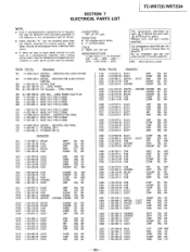
...(WR720A). . . .MOUNTED PCB, AUDIO SYSTEM CONTROL 901 *A-2006-258-A (WR720). . ..MOUNTED PCB, AUDIO SYSTEM CONTROL 902 *1-533-213-31 HOLDER, FUSE 903 1.1-551-188-XX (E)... .CORD, POWER 904 11-551-506-XX (US, Canadian). . ..CORD, POWER 905 1.1-555-795-00 (AEP, WG). . . .CORD, POWER, EULO PLUG 906 *1-575-847-11 WIRE,... • WG. . . . SECTION 7 ELECTRICAL PARTS LIST TC-WR720/WR720A NOTE: • Due to standardization, replacements in the parts list may be different from the parts specified in the diagrams or the components used on the set. • Items marked "*" are not stocked since they...
...(WR720A). . . .MOUNTED PCB, AUDIO SYSTEM CONTROL 901 *A-2006-258-A (WR720). . ..MOUNTED PCB, AUDIO SYSTEM CONTROL 902 *1-533-213-31 HOLDER, FUSE 903 1.1-551-188-XX (E)... .CORD, POWER 904 11-551-506-XX (US, Canadian). . ..CORD, POWER 905 1.1-555-795-00 (AEP, WG). . . .CORD, POWER, EULO PLUG 906 *1-575-847-11 WIRE,... • WG. . . . SECTION 7 ELECTRICAL PARTS LIST TC-WR720/WR720A NOTE: • Due to standardization, replacements in the parts list may be different from the parts specified in the diagrams or the components used on the set. • Items marked "*" are not stocked since they...

Service Manual
Page 27
...) SWITCH, KEY BOARD (A+B REC) SWITCH, KEY BOARD (AUTO PAUSE) SWITCH, KEY BOARD (BLANK SKIP) (WR720). . ..SWITCH, KEY BOARD (COUNTER A/B) S906 S907 S907 S908 S908 1-554-303-21 (WR720A). . . .SWITCH, KEY BOARD (COUNTER RESET) 1-554-303-21 (WR720). . . .SWITCH, KEY BOARD (COUNTER RESET) 1-554-303-21 (WR720A). . . .SWITCH, KEY BOARD (COUNTER MEMORY) 1-554-303-21 (WR720). ...SWITCH, KEY BOARD (COUNTER MEMORY) 1-554-303-21 (WR720A). . . .SWITCH...
...) SWITCH, KEY BOARD (A+B REC) SWITCH, KEY BOARD (AUTO PAUSE) SWITCH, KEY BOARD (BLANK SKIP) (WR720). . ..SWITCH, KEY BOARD (COUNTER A/B) S906 S907 S907 S908 S908 1-554-303-21 (WR720A). . . .SWITCH, KEY BOARD (COUNTER RESET) 1-554-303-21 (WR720). . . .SWITCH, KEY BOARD (COUNTER RESET) 1-554-303-21 (WR720A). . . .SWITCH, KEY BOARD (COUNTER MEMORY) 1-554-303-21 (WR720). ...SWITCH, KEY BOARD (COUNTER MEMORY) 1-554-303-21 (WR720A). . . .SWITCH...

Service Manual
Page 28
... (US). . . .INSTRUCTION *3-703-710-41 STICKER, SONY SYMBOL (12) 3-751-915-21 (WR720A). . . .MANUAL, INSTRUCTION (ENGLISH) 3-751-915-31 (Canadian, E). . . .MANUAL, INSTRUCTION (FRENCH) 3-751-921-11 (AEP). . . .MANUAL, INSTRUCTION (ENGLISH, FRENCH, SPANISH, PORTUGUESE) 3-751-921-41 (AEP). . . .MANUAL, INSTRUCTION (GERMAN, DUTCH, SWEDISH, ITALIAN) 3-751-921-51 (WG). . . .MANUAL, INSTRUCTION (GERMAN) TC-WR720/WR720A -41 Note: The components identified by mark Qi or dotted line with part number specified.
... (US). . . .INSTRUCTION *3-703-710-41 STICKER, SONY SYMBOL (12) 3-751-915-21 (WR720A). . . .MANUAL, INSTRUCTION (ENGLISH) 3-751-915-31 (Canadian, E). . . .MANUAL, INSTRUCTION (FRENCH) 3-751-921-11 (AEP). . . .MANUAL, INSTRUCTION (ENGLISH, FRENCH, SPANISH, PORTUGUESE) 3-751-921-41 (AEP). . . .MANUAL, INSTRUCTION (GERMAN, DUTCH, SWEDISH, ITALIAN) 3-751-921-51 (WG). . . .MANUAL, INSTRUCTION (GERMAN) TC-WR720/WR720A -41 Note: The components identified by mark Qi or dotted line with part number specified.
Service Manual
Page 30
TC-WR120/WR120A SONY.. Subject : block diagram US Model Canadian Model E Model TC-WR720A AEP Model TC-WR720 9-955-929-81 Sony Corporation Audio Group English 90L0481-1 Printed in Japan 0 1990. 12 Published by Customer Relations and Service Group SERVICE MANUAL SUPPLEMENT-1 File this supplement with the Service Manual.
TC-WR120/WR120A SONY.. Subject : block diagram US Model Canadian Model E Model TC-WR720A AEP Model TC-WR720 9-955-929-81 Sony Corporation Audio Group English 90L0481-1 Printed in Japan 0 1990. 12 Published by Customer Relations and Service Group SERVICE MANUAL SUPPLEMENT-1 File this supplement with the Service Manual.
Service Manual
Page 31
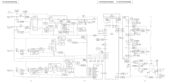
... DOLBY FM PRO RV391 REC LEVEL L-CH(B) VCA DET 3 PRE DRIVE R-CH IC501(1/2) DOLBY NR IC504 METER AMP 5 >7 EQ SWITCH 0101 -F1 3 MODE CONTROL 4 26 5 MUTING 0171 R CH 'MUTING DRIVE 0571.572 LPF101 REC/PB SWITCH 0502 REC/PB PB ED SWITC R CH -• I C70111/2) TO FLOOI X X -28V REC 28V 0703,704 T701 POWER TRANSFORMER S701-1 POWER EXCEPT E MODEL (r 11 AC IN ON E MODEL...
... DOLBY FM PRO RV391 REC LEVEL L-CH(B) VCA DET 3 PRE DRIVE R-CH IC501(1/2) DOLBY NR IC504 METER AMP 5 >7 EQ SWITCH 0101 -F1 3 MODE CONTROL 4 26 5 MUTING 0171 R CH 'MUTING DRIVE 0571.572 LPF101 REC/PB SWITCH 0502 REC/PB PB ED SWITC R CH -• I C70111/2) TO FLOOI X X -28V REC 28V 0703,704 T701 POWER TRANSFORMER S701-1 POWER EXCEPT E MODEL (r 11 AC IN ON E MODEL...
Service Manual
Page 32
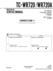
TC-WR720 /WR720A SERVMAINCUAEL US Model Canadian Model E Model TC-WR720A AEP Model TC-WR720 CORRECTION-1 Correct your service manual as shown below. Page INCORRECT Playback Level Adjustment . • . . 10 .• Adjustment limits : LINE OUT level : -15±0.5dB(0.130 to 0.146V) CORRECT Playback Level Adjustment : : . . • Adjustment limits : LINE OUT level : -5±0.5dB(0.411 to 0.462V) I 41 9-955-929-91 Sony Corporation Audio Group English 93J0487-1D Printed in Japan ©...
TC-WR720 /WR720A SERVMAINCUAEL US Model Canadian Model E Model TC-WR720A AEP Model TC-WR720 CORRECTION-1 Correct your service manual as shown below. Page INCORRECT Playback Level Adjustment . • . . 10 .• Adjustment limits : LINE OUT level : -15±0.5dB(0.130 to 0.146V) CORRECT Playback Level Adjustment : : . . • Adjustment limits : LINE OUT level : -5±0.5dB(0.411 to 0.462V) I 41 9-955-929-91 Sony Corporation Audio Group English 93J0487-1D Printed in Japan ©...

