Sony TC-WR720A - Dual Cassette Deck Support and Manuals
Get Help and Manuals for this Sony item

View All Support Options Below
Free Sony TC-WR720A manuals!
Problems with Sony TC-WR720A?
Ask a Question
Free Sony TC-WR720A manuals!
Problems with Sony TC-WR720A?
Ask a Question
Popular Sony TC-WR720A Manual Pages
Service Manual - Page 1
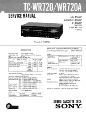
SERVICE MANUAL
0> •
US Model Canadian Model
E Model
TC-WR720A
AEP Model
TC-WR720
This photo is TC-WR720.
Refe: f0 nearidopa!c,D;.unler,ts
Model Name Using Similar Mechanism TC-WR620
Tape Transport Mechanism Type
TCM-19ORBld
Output
Line outputs (phono jacks)
Rated output level
Headphones (stereo phono jack)
Load impedance Output level
0.44V (-5dB) ...
Service Manual - Page 2
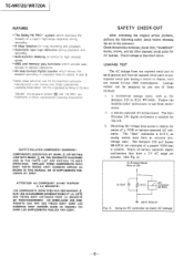
... license from all other exposed metal parts for this job.
3.
"DOLBY' , the double-D symbol DO and - REPLACE THESE COMPONENTS WITH SONY PARTS WHOSE PART NUMBERS APPEAR AS SHOWN IN THIS MANUAL OR IN SUPPLEMENTS PUBLISHED BY SONY.
Leakage current can be measured by Bang & Olufsen. I. HX PRO-
A)
To Exposed Metal Parts on Set
0.15µF
1.5kf2
AC
voltmeter (0.751...
Service Manual - Page 3

... Boards -Main Section-
14
5-4. -MODEL IDENTIFICATION(Specification Label)
TC-W720: AEP, WG (West Germany) model
SONY® MODEL NO. TC-WR720
STEREO CASSETTE DECK AC 220V - 50/60Hz
TC-WR720A: US, Canadian, E model
SONY® MODEL NO. TC-WR720A
STEREO CASSETTE DECK
US, Canadian model: AC 120V 60Hz 33W E model: AC 120, 220, 240V - 50/60Hz 33W
TC-WR720/WR720A
TABLE OF CONTENTS
Section...
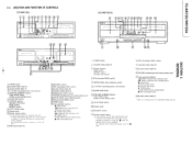
Service Manual - Page 4
t 6
1 J .L.J
• i-H1 E-- - Emii
SONY
2 13 14 15
(TC-WR720A) i3
SONY -st
61 il8 9 W111 12 131 A
• Ai i
..k_ l' F I
E, Liu= fraj_c_p
1
18...(recording) button
eject button (deck A)
AIMS is an abbreviation for Automatic Music Sensor el)
:„- Any optional Sony remote commander von) the 1A mark
.111 BIAS control (deck B)
121 BALANCE control REC (recording) LEVEL control
...
Service Manual - Page 7
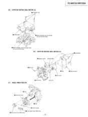
... lever FWD) assy 0 lever (pinch lever REV) assy
-7- CAPSTAN MOTOR, REEL MOTOR (2)
0 capstan motor ground plate
0 connectors
0 B2.6x3
2-7. CAPSTAN MOTOR, REEL MOTOR (1) 0 PTPWH2 X23
TC-WR720/WR720A
0 fitting base
4
rr
0 When installing, pull the FR belt
and put arround claws. ( 1)
0 When installing, pull the capstan belt
and put arround claws.
2-6. 2-5.
Service Manual - Page 8
...with a denatured alcohol-
TC-WR720/WR720A
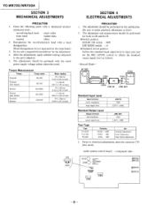
SECTION 3 MECHANICAL ADJUSTMENTS
...PRECAUTION
1. Do not use a magnetized screwdriver for the erase head.)
3.
The adjustments should be perfomed with the rated
power supply voltage unless otherwise noted. AF OSC
VTVM
0
attenuator 10k0
O--I-° OO O
set the REC LEVEL control to the parts...
Service Manual - Page 14
...11/21
95216AP
CN505
%00274I 5 J50
1
_J PHONES
_ _
(
no -signal
conditions. E MODEL
WR72 OA - 1_
•E NOT REPLACEABLE,
[NX - S.
91] 72
R2727,2
•
LINE OUT
R59I
qr 220
C59I + I0004... resistors are critical for repair. une marque Z1\ sont critiques
ted line with part piece portant le numero speci
number specified.
5-4.
WR720A
IC601 HEADPHONE AMP
J301 ...
Service Manual - Page 17

... JO
N
3
15- CHASSIS SECTION
5
WR720A
SECTION 6 EXPLODED VIEWS
• Due to standardization, parts with part number suffix -XX and -X may be anticipated when ordering these items.
6-1.
Les composants identifies par une marque Qi sont critiques pour la securite. Replace only with a collation number in the components used on the set.
• Color Indication of an...
Service Manual - Page 22
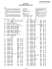
... critical for safety. Ref.No Part No. SECTION 7 ELECTRICAL PARTS LIST
TC-WR720/WR720A
NOTE:
• Due to standardization, replacements in the parts list may be different from the parts specified in the diagrams or the components used on the set.
• Items marked "*" are not stocked since they are seldom required for routine service. Description
901 *A-2006-254...
Service Manual - Page 23

Note:
Les composants identifies par une marque 0 sont critiques pour la securite. TC-WR720/WR720A
Ref.No Part No. Description
C702 C703 C704
C705 C707
1-124-122-11 ELECT 1-124-925-11 ELECT 1-124-911-11 ELECT... IC RC4558P
8-759-945-58 IC RC4558P
-36-
Note:
The components identified by mark 0or dotted line with part number specified.
Replace only with mark are critical for safety.
Service Manual - Page 28

...) 3-751-921-41 (AEP). . . .MANUAL, INSTRUCTION
(GERMAN, DUTCH, SWEDISH, ITALIAN) 3-751-921-51 (WG). . . .MANUAL, INSTRUCTION
(GERMAN)
TC-WR720/WR720A
-41
Note: The components identified by mark Qi or dotted line with part
number specified.
Ref.No Part No. Note: Les composants identifies par une marque Isont critiques pour la securite. fie.
Replace only with mark are critical for...
Service Manual - Page 29
TC-WR720/WR720A
9-955-929-11
Sony Corporation
Audio Group
English 90F0477-1 Printed in Japan
© 1990. 6
Service Manual - Page 30
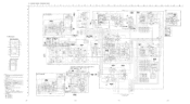
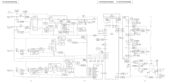
Subject : block diagram
US Model Canadian Model
E Model TC-WR720A
AEP Model
TC-WR720
9-955-929-81
Sony Corporation
Audio Group
English 90L0481-1 Printed in Japan 0 1990. 12
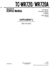
Published by Customer Relations and Service Group TC-WR120/WR120A
SONY.. SERVICE MANUAL
SUPPLEMENT-1
File this supplement with the Service Manual.
Service Manual - Page 31
TC-WR720/WR720A
TC-WR720/WR720A TC-WR720/WR720A
J301 -I C503
0501
-.03 6020- RO1 ...WR720A)
REG LEVEL
IC3I(A) PB ELI AMP
REG 0
7t.
DOLBY B/C
B/C
0504
A
AMS AMP
7
3\1
DOLBY SWITCH 0505
AMS/BS SELECT
0601
•- -
DECK:B
RV501-1(WR720) RV902-I C70111/2)
TO FLOOI
X X
-28V REC
28V
0703,704
T701 POWER TRANSFORMER
S701-1 POWER
EXCEPT E MODEL
(r 11
AC IN
ON
E MODEL...
Service Manual - Page 32
... : : . .
•
Adjustment limits : LINE OUT level : -5±0.5dB(0.411 to 0.462V)
I
41
9-955-929-91
Sony Corporation
Audio Group
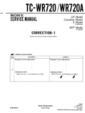
English 93J0487-1D Printed in Japan © 1993.10 Published by Audio Sector Quality Assurance Dept. TC-WR720 /WR720A
SERVMAINCUAEL
US Model Canadian Model
E Model
TC-WR720A
AEP Model
TC-WR720
CORRECTION-1
Correct your service manual as shown below.
Sony TC-WR720A Reviews
We have not received any reviews for Sony yet.