Operating Instructions
Page 4
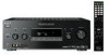
............21 4b: Connecting the video components ........22 5: Connecting the antennas (aerials 28 6: Preparing the receiver and the remote .....29 7: Selecting the speaker system 30 8: Calibrating the appropriate settings automatically (AUTO CALIBRATION 31 9: Adjusting the speaker levels and balance (TEST TONE 37 Playback Selecting a...speakers (2CH STEREO 62 Listening to the sound without any adjustment (ANALOG DIRECT 62 Resetting sound fields to the initial settings 63 Tuner Operations Listening to FM/AM radio 63 Presetting radio stations 65 Listening to the XM Radio 68 Presetting XM...
............21 4b: Connecting the video components ........22 5: Connecting the antennas (aerials 28 6: Preparing the receiver and the remote .....29 7: Selecting the speaker system 30 8: Calibrating the appropriate settings automatically (AUTO CALIBRATION 31 9: Adjusting the speaker levels and balance (TEST TONE 37 Playback Selecting a...speakers (2CH STEREO 62 Listening to the sound without any adjustment (ANALOG DIRECT 62 Resetting sound fields to the initial settings 63 Tuner Operations Listening to FM/AM radio 63 Presetting radio stations 65 Listening to the XM Radio 68 Presetting XM...
Operating Instructions
Page 6
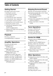
...Standby Press ?/1 on the remote to standby mode. 6US Status of the POWER button Off The receiver is on or set to turn the receiver on . The ON/STANDBY lamp lights up in red when the receiver is set it out of parts Front panel 1 2 3 45 6 78 9 ON/STANDBY POWER SPEAKERS (...OFF/A/B/A+B) TONE MODE TONE TUNING MODE TUNING PHONES VIDEO 2 IN/PORTABLE AV IN VIDEO L AUDIO R AUTO CAL MIC DISPLAY INPUT MODE INPUT SELECTOR MEMORY/ ...
...Standby Press ?/1 on the remote to standby mode. 6US Status of the POWER button Off The receiver is on or set to turn the receiver on . The ON/STANDBY lamp lights up in red when the receiver is set it out of parts Front panel 1 2 3 45 6 78 9 ON/STANDBY POWER SPEAKERS (...OFF/A/B/A+B) TONE MODE TONE TUNING MODE TUNING PHONES VIDEO 2 IN/PORTABLE AV IN VIDEO L AUDIO R AUTO CAL MIC DISPLAY INPUT MODE INPUT SELECTOR MEMORY/ ...
Operating Instructions
Page 7
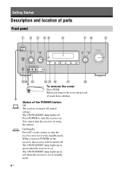
...M MEMORY/ ENTER Press to select bass or treble level, then turn the receiver on the display (page 72, 88, 101). D TUNING +/- Press TONE MODE repeatedly to store a station or enter the selection when selecting the settings (page 65, 72). Q PHONES jack Connects to a portable audio/video component... such as a camcorder or video game (page 27, 38). O VIDEO 2 IN/ PORTABLE AV IN jacks Connects to headphones (page 99). 7US ON/STANDBY...
...M MEMORY/ ENTER Press to select bass or treble level, then turn the receiver on the display (page 72, 88, 101). D TUNING +/- Press TONE MODE repeatedly to store a station or enter the selection when selecting the settings (page 65, 72). Q PHONES jack Connects to a portable audio/video component... such as a camcorder or video game (page 27, 38). O VIDEO 2 IN/ PORTABLE AV IN jacks Connects to headphones (page 99). 7US ON/STANDBY...
Operating Instructions
Page 8
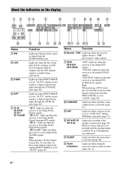
... "AUTO" and the source signal is decoding Dolby Digital Surround EX signals. L Tuner indicators Lights up when the receiver is set to tune in radio stations (page 63), etc. 8US About the indicators on the display 1 2 34 5 6 7 8 9 0 qa wf Name A SW B LFE C COAX D OPT E...Note When playing a Dolby Digital format disc, be sure that you have made digital connections and that INPUT MODE is set to "AUTO" (page 82). "; "; Lights up when the receiver is a digital signal being reproduced. THX processing to "AUTO" and the source signal is decoding DTS 96 kHz/24...
... "AUTO" and the source signal is decoding Dolby Digital Surround EX signals. L Tuner indicators Lights up when the receiver is set to tune in radio stations (page 63), etc. 8US About the indicators on the display 1 2 34 5 6 7 8 9 0 qa wf Name A SW B LFE C COAX D OPT E...Note When playing a Dolby Digital format disc, be sure that you have made digital connections and that INPUT MODE is set to "AUTO" (page 82). "; "; Lights up when the receiver is a digital signal being reproduced. THX processing to "AUTO" and the source signal is decoding DTS 96 kHz/24...
Operating Instructions
Page 9
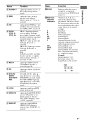
... does not function for signals with a sampling frequency of more than 48 kHz. Lights up when the receiver is activated (page 58). Lights up when the Pro Logic IIx decoder is set to "AUTO" (page 82). AUTO SW LCR SL SR 9US PL IIx" lights up when INPUT... channel indicators L R C SL SR S SBL SBR SB Function Lights up when the receiver applies Pro Logic processing to 2 channel signals in order to show how the receiver downmixes the source sound (based on the speaker settings). Front Left Front Right Center (monaural) Surround Left Surround Right Surround (monaural or the ...
... does not function for signals with a sampling frequency of more than 48 kHz. Lights up when the receiver is activated (page 58). Lights up when the Pro Logic IIx decoder is set to "AUTO" (page 82). AUTO SW LCR SL SR 9US PL IIx" lights up when INPUT... channel indicators L R C SL SR S SBL SBR SB Function Lights up when the receiver applies Pro Logic processing to 2 channel signals in order to show how the receiver downmixes the source sound (based on the speaker settings). Front Left Front Right Center (monaural) Surround Left Surround Right Surround (monaural or the ...
Operating Instructions
Page 11
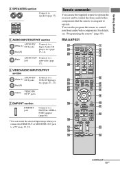
... TOP MENU MENU F1 F2 TV INPUT WIDE 0 qa qs qd qf continued 11US RM-AAP021 wj wh wg wf wd ws wa w; ?/1 THEATER RM SET UP AV ?/1 SYSTEM STANDBY SHIFT TV AMP 1 VIDEO 1 4 DVD 7 -/-- 2 VIDEO 2 5 SAT 8 SA-CD/ CD 0/10 CLEAR/>10 XM 3 BD 6 TV 9 TUNER ENT/MEM DMPORT 2CH.../ A.DIRECT A.F.D. You can use the supplied remote to operate the receiver and to control the Sony audio/video components that the remote is assigned to operate. ql ...
... TOP MENU MENU F1 F2 TV INPUT WIDE 0 qa qs qd qf continued 11US RM-AAP021 wj wh wg wf wd ws wa w; ?/1 THEATER RM SET UP AV ?/1 SYSTEM STANDBY SHIFT TV AMP 1 VIDEO 1 4 DVD 7 -/-- 2 VIDEO 2 5 SAT 8 SA-CD/ CD 0/10 CLEAR/>10 XM 3 BD 6 TV 9 TUNER ENT/MEM DMPORT 2CH.../ A.DIRECT A.F.D. You can use the supplied remote to operate the receiver and to control the Sony audio/video components that the remote is assigned to operate. ql ...
Operating Instructions
Page 12
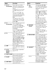
.... Press also to enter the selection of Sony TV, press TV (C) and then press MENU. Press to display and select items from the options menus for receiver operation, then press V/v/B /b to select the settings. To turn off all components, press ?/1 and AV ?/1 (A) at the same time, it to... to perform menu operations. Press to skip tracks of the AV ?/1 switch changes automatically each time you press ?/1 (B) at the same time (SYSTEM STANDBY). To save the power in standby mode, set it will turn off the receiver and other components (SYSTEM STANDBY). D AMP Press to light...
.... Press also to enter the selection of Sony TV, press TV (C) and then press MENU. Press to display and select items from the options menus for receiver operation, then press V/v/B /b to select the settings. To turn off all components, press ?/1 and AV ?/1 (A) at the same time, it to... to perform menu operations. Press to skip tracks of the AV ?/1 switch changes automatically each time you press ?/1 (B) at the same time (SYSTEM STANDBY). To save the power in standby mode, set it will turn off the receiver and other components (SYSTEM STANDBY). D AMP Press to light...
Operating Instructions
Page 15
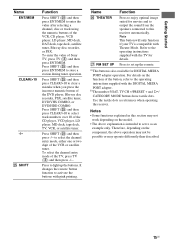
...example only. To enter the value of the VCR or satellite tuner. to select the channel entry mode, either one or two digit of Sony TV, press TV (C) and then press ENT/MEM. For details on the function of the button, refer to the operating instructions supplied with... is intended to serve as references when operating the receiver. Notes • Some functions explained in this receiver automatically. It changes the remote button function to activate the buttons with the DIGITAL MEDIA PORT adapter. wj RM SET UP Press to set up the buttons. a)This button is compatible with ...
...example only. To enter the value of the VCR or satellite tuner. to select the channel entry mode, either one or two digit of Sony TV, press TV (C) and then press ENT/MEM. For details on the function of the button, refer to the operating instructions supplied with... is intended to serve as references when operating the receiver. Notes • Some functions explained in this receiver automatically. It changes the remote button function to activate the buttons with the DIGITAL MEDIA PORT adapter. wj RM SET UP Press to set up the buttons. a)This button is compatible with ...
Operating Instructions
Page 18
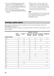
... connect them to standby mode automatically based on the receiver (page 30). b)If you connect only one surround...connect a subwoofer with the SPEAKERS (OFF/A/B/A+B) button on the level of each other between the SPEAKERS terminals. a)If you have install and connect your speaker setting. Speaker pattern 3/4.1 3/4 3/3.1 3/3 2/4.1 2/4 3/2.1 3/2 2/3.1 2/3 2/2.1 2/2 3/0.1 3/0 2/0.1 2/0 Front Center left/right Speaker connected Surround Surround Surround Subwoofer left/right back left back right a a a a a a a a a a a a a a a a a a a a a a a a a a a a a a a...
... connect them to standby mode automatically based on the receiver (page 30). b)If you connect only one surround...connect a subwoofer with the SPEAKERS (OFF/A/B/A+B) button on the level of each other between the SPEAKERS terminals. a)If you have install and connect your speaker setting. Speaker pattern 3/4.1 3/4 3/3.1 3/3 2/4.1 2/4 3/2.1 3/2 2/3.1 2/3 2/2.1 2/2 3/0.1 3/0 2/0.1 2/0 Front Center left/right Speaker connected Surround Surround Surround Subwoofer left/right back left back right a a a a a a a a a a a a a a a a a a a a a a a a a a a a a a a...
Operating Instructions
Page 22
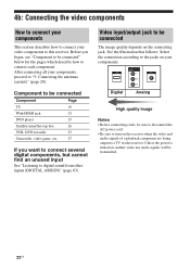
... the video and audio signals of a playback component are being output to a TV via the receiver. Unless the power is turned on your video components to this receiver. See the illustration that follows. Select the connection according to the jacks on , neither video nor audio signals will ... "5: Connecting the antennas (aerials)" (page 28). Component to be connected Component Page TV 19 With HDMI jack 23 DVD player 25 Satellite tuner/Set-top box 26 VCR, DVD recorder 27 Camcorder, video game, etc. 27 If you begin, see "Component to be transmitted. 22US 4b: ...
... the video and audio signals of a playback component are being output to a TV via the receiver. Unless the power is turned on your video components to this receiver. See the illustration that follows. Select the connection according to the jacks on , neither video nor audio signals will ... "5: Connecting the antennas (aerials)" (page 28). Component to be connected Component Page TV 19 With HDMI jack 23 DVD player 25 Satellite tuner/Set-top box 26 VCR, DVD recorder 27 Camcorder, video game, etc. 27 If you begin, see "Component to be transmitted. 22US 4b: ...
Operating Instructions
Page 24
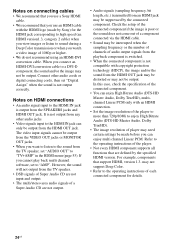
... the SPEAKERS jacks and HDMI OUT jack. Notes on connecting cables • We recommend that you use a Sony HDMI cable. • We recommend that you use an HDMI cable with an HDMI connection. • Set the image resolution of the player to more than 720p/1080i to enjoy High Bitrate Audio (DTS...-HD Master Audio, Dolby TrueHD). • The image resolution of player may not be made by Sony) for details. 24US The video input signals cannot be...
... the SPEAKERS jacks and HDMI OUT jack. Notes on connecting cables • We recommend that you use a Sony HDMI cable. • We recommend that you use an HDMI cable with an HDMI connection. • Set the image resolution of the player to more than 720p/1080i to enjoy High Bitrate Audio (DTS...-HD Master Audio, Dolby TrueHD). • The image resolution of player may not be made by Sony) for details. 24US The video input signals cannot be...
Operating Instructions
Page 25
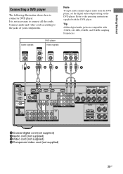
Note To input multi channel digital audio from the DVD player, set the digital audio output setting on the DVD player. Refer to connect a DVD player. Tip All the digital audio jacks are compatible with the DVD player. Getting Started Connecting a DVD ...
Note To input multi channel digital audio from the DVD player, set the digital audio output setting on the DVD player. Refer to connect a DVD player. Tip All the digital audio jacks are compatible with the DVD player. Getting Started Connecting a DVD ...
Operating Instructions
Page 26
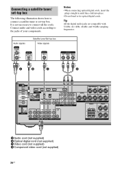
... straight in until they click into place. • Do not bend or tie optical digital cords. Connecting a satellite tuner/ set -top box. Connect audio and video cords according to connect a satellite tuner or set -top box The following illustration shows how to the jacks of your components. A B C D TV OPTICAL IN VIDEO 1 IN...
... straight in until they click into place. • Do not bend or tie optical digital cords. Connecting a satellite tuner/ set -top box. Connect audio and video cords according to connect a satellite tuner or set -top box The following illustration shows how to the jacks of your components. A B C D TV OPTICAL IN VIDEO 1 IN...
Operating Instructions
Page 27
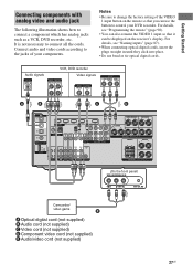
... see "Programming the remote" (page 90). • You can also rename the VIDEO 1 input so that you can be displayed on the receiver's display. It is not necessary to connect a component which has analog jacks such as a VCR, DVD recorder, etc. For details, see ...TV SAT DVD VIDEO 1 SUBWOOFER SURROUND BACK SURROUND L L CENTER R R SPEAKERS FRONT B R L FRONT A L R SPEAKERS (On the front panel) VIDEO 2 IN/PORTABLE AV IN VIDEO L AUDIO R AUTO CAL MIC Camcorder/ video game E A Optical digital cord (not supplied) B Audio cord (not supplied) C Video cord (not supplied) D ...
... see "Programming the remote" (page 90). • You can also rename the VIDEO 1 input so that you can be displayed on the receiver's display. It is not necessary to connect a component which has analog jacks such as a VCR, DVD recorder, etc. For details, see ...TV SAT DVD VIDEO 1 SUBWOOFER SURROUND BACK SURROUND L L CENTER R R SPEAKERS FRONT B R L FRONT A L R SPEAKERS (On the front panel) VIDEO 2 IN/PORTABLE AV IN VIDEO L AUDIO R AUTO CAL MIC Camcorder/ video game E A Optical digital cord (not supplied) B Audio cord (not supplied) C Video cord (not supplied) D ...

Operating Instructions
Page 29
... appears. After "CLEARING" appears on the receiver for the first time, initialize the receiver by performing the following procedure. This procedure can also be used to return settings you have made to the initial settings. 29US MOVIE MUSIC MASTER VOLUME 2,3 1 ... A L R SPEAKERS To the wall outlet Performing initial setup operations Before using the receiver for this operation. 1,2 2,3 ON/STANDBY POWER SPEAKERS (OFF/A/B/A+B) TONE MODE TONE TUNING MODE TUNING PHONES VIDEO 2 IN/PORTABLE AV IN VIDEO L AUDIO R AUTO CAL MIC DISPLAY INPUT MODE INPUT SELECTOR MEMORY/ ENTER...
... appears. After "CLEARING" appears on the receiver for the first time, initialize the receiver by performing the following procedure. This procedure can also be used to return settings you have made to the initial settings. 29US MOVIE MUSIC MASTER VOLUME 2,3 1 ... A L R SPEAKERS To the wall outlet Performing initial setup operations Before using the receiver for this operation. 1,2 2,3 ON/STANDBY POWER SPEAKERS (OFF/A/B/A+B) TONE MODE TONE TUNING MODE TUNING PHONES VIDEO 2 IN/PORTABLE AV IN VIDEO L AUDIO R AUTO CAL MIC DISPLAY INPUT MODE INPUT SELECTOR MEMORY/ ENTER...
Operating Instructions
Page 31
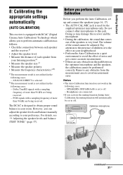
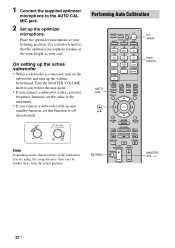
...Remove any obstacles in the following cases. - ON/STANDBY POWER SPEAKERS (OFF/A/B/A+B) TONE MODE TONE TUNING MODE TUNING PHONES VIDEO 2 IN/PORTABLE AV IN VIDEO L AUDIO R AUTO CAL MIC DISPLAY INPUT MODE INPUT SELECTOR MEMORY/ ENTER DIMMER 2CH/ A.DIRECT A.F.D. Dolby TrueHD signals with a ... area to avoid measurement error. Before you perform Auto Calibration Before you perform the Auto Calibration, set to avoid the effect of more than 96 kHz are being received. - ANALOG DIRECT is very loud. However, you activate the muting function during Auto Calibration, ...
...Remove any obstacles in the following cases. - ON/STANDBY POWER SPEAKERS (OFF/A/B/A+B) TONE MODE TONE TUNING MODE TUNING PHONES VIDEO 2 IN/PORTABLE AV IN VIDEO L AUDIO R AUTO CAL MIC DISPLAY INPUT MODE INPUT SELECTOR MEMORY/ ENTER DIMMER 2CH/ A.DIRECT A.F.D. Dolby TrueHD signals with a ... area to avoid measurement error. Before you perform Auto Calibration Before you perform the Auto Calibration, set to avoid the effect of more than 96 kHz are being received. - ANALOG DIRECT is very loud. However, you activate the muting function during Auto Calibration, ...
Operating Instructions
Page 32
Turn the MASTER VOLUME knob to just before the mid-point. • If you connect a subwoofer with an auto standby function, set the value to the maximum. • If you are using, the setup distance value may be further away from the actual position. MOVIE ... VOL PRESET MUTING MASTER VOL +/- 32US Place the optimizer microphone at the same height as your listening position. Performing Auto Calibration AUTO CAL ?/1 THEATER RM SET UP AV ?/1 SYSTEM STANDBY SHIFT TV AMP 1 VIDEO 1 4 DVD 7 -/-- 2 VIDEO 2 5 SAT 8 SA-CD/ CD 0/10 CLEAR/>10 XM 3 BD 6 TV 9 TUNER ENT/MEM DMPORT 2CH/...
Turn the MASTER VOLUME knob to just before the mid-point. • If you connect a subwoofer with an auto standby function, set the value to the maximum. • If you are using, the setup distance value may be further away from the actual position. MOVIE ... VOL PRESET MUTING MASTER VOL +/- 32US Place the optimizer microphone at the same height as your listening position. Performing Auto Calibration AUTO CAL ?/1 THEATER RM SET UP AV ?/1 SYSTEM STANDBY SHIFT TV AMP 1 VIDEO 1 4 DVD 7 -/-- 2 VIDEO 2 5 SAT 8 SA-CD/ CD 0/10 CLEAR/>10 XM 3 BD 6 TV 9 TUNER ENT/MEM DMPORT 2CH/...
Operating Instructions
Page 33
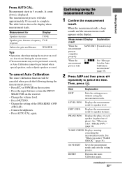
...the Auto Calibration again. Measurement for speaker level. When the measurement ends, a beep sounds and the measurement result appears on the receiver. - Then, press . Press AUTO CAL again. When the measurement process fails E - Displays the measurement result for Display Speaker...starts. response Subwoofer gain and distance WOOFER Tips • Operations other than turning the receiver on the receiver. - Item Explanation EXIT Exits the setting process without saving the measurement results. Displays the measurement result for speaker distance. SAVE ...
...the Auto Calibration again. Measurement for speaker level. When the measurement ends, a beep sounds and the measurement result appears on the receiver. - Then, press . Press AUTO CAL again. When the measurement process fails E - Displays the measurement result for Display Speaker...starts. response Subwoofer gain and distance WOOFER Tips • Operations other than turning the receiver on the receiver. - Item Explanation EXIT Exits the setting process without saving the measurement results. Displays the measurement result for speaker distance. SAVE ...
Operating Instructions
Page 34
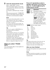
.... You can select the calibration type in the SPEAKER menu (page 47). xxx* - OUT" appears on the display and the settings are connected properly. F Front FL Front left FR Front right CNT Center S Surround SL Surround left SR Surround right SB Surround back...have finished Disconnect the optimizer microphone from the receiver. Save the measurement results first, then try to use the receiver. * xxx represent a speaker channel. Display Explanation xxx* - The measurement results are saved and you continue to change those settings in the AUTO CAL menu. For details,...
.... You can select the calibration type in the SPEAKER menu (page 47). xxx* - OUT" appears on the display and the settings are connected properly. F Front FL Front left FR Front right CNT Center S Surround SL Surround left SR Surround right SB Surround back...have finished Disconnect the optimizer microphone from the receiver. Save the measurement results first, then try to use the receiver. * xxx represent a speaker channel. Display Explanation xxx* - The measurement results are saved and you continue to change those settings in the AUTO CAL menu. For details,...
Operating Instructions
Page 35
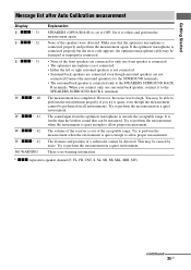
...range. The volume of the front speakers are not connected.Connect the surround speaker(s) to the SURROUND terminals. • The surround back speaker is set to the SPEAKERS SURROUND BACK L terminals. However, the noise level is connected properly and perform the measurement again. xxx* : 32 E - ... is connected properly but the error code appears, the optimizer microphone cable may be damaged or improperly connected. • None of the receiver is louder than the loudest sound that the optimizer microphone is high. xxx* : 31 E - xxx* : 43 NO WARNING Explanation...
...range. The volume of the front speakers are not connected.Connect the surround speaker(s) to the SURROUND terminals. • The surround back speaker is set to the SPEAKERS SURROUND BACK L terminals. However, the noise level is connected properly and perform the measurement again. xxx* : 32 E - ... is connected properly but the error code appears, the optimizer microphone cable may be damaged or improperly connected. • None of the receiver is louder than the loudest sound that the optimizer microphone is high. xxx* : 31 E - xxx* : 43 NO WARNING Explanation...


