Limited Warranty (ES Products)
Page 1
...-02 General Stereo/Hifi Components/Tape Decks ® CD Players/Mini Disc Players/Audio Systems LIMITED WARRANTY Hifi Audio ES Products Sony Electronics Inc. ("Sony") warrants this Product is invalid if the factory applied serial number has been altered or removed from the Product. For your authorized dealer, call : Sony Customer Information Services Center 1-800-222-7669 or visit the Sony Web Site: www.sony.com For an accessory or part not...
...-02 General Stereo/Hifi Components/Tape Decks ® CD Players/Mini Disc Players/Audio Systems LIMITED WARRANTY Hifi Audio ES Products Sony Electronics Inc. ("Sony") warrants this Product is invalid if the factory applied serial number has been altered or removed from the Product. For your authorized dealer, call : Sony Customer Information Services Center 1-800-222-7669 or visit the Sony Web Site: www.sony.com For an accessory or part not...
Operating Instructions
Page 2
... radiate radio frequency energy and, if not installed and used in a confined space, such as alcohol or benzine. Consult the dealer or an experienced radio/TV technician for a long time, be changed only at the rear of the plug is a U.S. Do not install the appliance in accordance with the instructions, may be determined by turning the equipment off and unplug the receiver. Connect the...
... radiate radio frequency energy and, if not installed and used in a confined space, such as alcohol or benzine. Consult the dealer or an experienced radio/TV technician for a long time, be changed only at the rear of the plug is a U.S. Do not install the appliance in accordance with the instructions, may be determined by turning the equipment off and unplug the receiver. Connect the...
Operating Instructions
Page 3
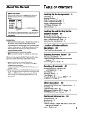
.... IMPEDANCE USE 4-16Ω R REAR L CENTER + R L REAR - Hooking Up the Components 4 Unpacking 4 Antenna Hookups 5 Audio Component Hookups 6 Video Component Hookups 7 Digital Component Hookups 8 5.1CH Input Hookups 10 Other Hookups 11 Hooking Up and Setting Up the Speaker System 14 Speaker System Hookup 15 Performing Initial Setup Operations 17 Multi Channel Surround Setup 18 Before You Use Your Receiver 23 Location of Parts and Basic Operations 24 Front Panel Parts Description 24 Enjoying Surround Sound 29 Selecting a Sound Field 30 Understanding the Multi-Channel Surround...
.... IMPEDANCE USE 4-16Ω R REAR L CENTER + R L REAR - Hooking Up the Components 4 Unpacking 4 Antenna Hookups 5 Audio Component Hookups 6 Video Component Hookups 7 Digital Component Hookups 8 5.1CH Input Hookups 10 Other Hookups 11 Hooking Up and Setting Up the Speaker System 14 Speaker System Hookup 15 Performing Initial Setup Operations 17 Multi Channel Surround Setup 18 Before You Use Your Receiver 23 Location of Parts and Basic Operations 24 Front Panel Parts Description 24 Enjoying Surround Sound 29 Selecting a Sound Field 30 Understanding the Multi-Channel Surround...

Operating Instructions
Page 7
R PRE OUT IMPEDANCE USE 4-16Ω R REAR L CENTER + R L REAR - CENTER + - Note on video component hookups You can connect your TV's audio output jacks to the TV/ SAT AUDIO IN jacks on the receiver and apply sound effects to the receiver as shown above. OUT IN AUDIO OUT IN OUT IN AUDIO OUT TAPE 2ND AV 5.1CH INPUT FRONT REAR CENTER L R + SUB WOOFER FRONT REAR SUB WOOFER CENTER L - If you are on the front panel 1) You can use the video cord of the supplied audio/video/control S cord. (Models of the video jacks Your...
R PRE OUT IMPEDANCE USE 4-16Ω R REAR L CENTER + R L REAR - CENTER + - Note on video component hookups You can connect your TV's audio output jacks to the TV/ SAT AUDIO IN jacks on the receiver and apply sound effects to the receiver as shown above. OUT IN AUDIO OUT IN OUT IN AUDIO OUT TAPE 2ND AV 5.1CH INPUT FRONT REAR CENTER L R + SUB WOOFER FRONT REAR SUB WOOFER CENTER L - If you are on the front panel 1) You can use the video cord of the supplied audio/video/control S cord. (Models of the video jacks Your...
Operating Instructions
Page 8
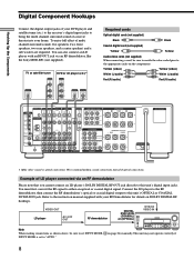
... the multi channel surround sound of a movie theater into your home. You can also connect an LD player with your RF Demodulator for details on page 24) manually. IMPEDANCE SELECTOR 4 Ω 8 Ω AC OUTLET * Make either an optical or coaxial digital signal. OUT IN AUDIO OUT IN OUT IN AUDIO OUT TAPE 2ND AV 5.1CH INPUT FRONT REAR CENTER L R + SUB WOOFER FRONT REAR SUB WOOFER CENTER L - Hooking Up the Components Digital Component Hookups Connect the digital output jacks of your DVD player and satellite tuner (etc.) to the receiver's digital input jacks...
... the multi channel surround sound of a movie theater into your home. You can also connect an LD player with your RF Demodulator for details on page 24) manually. IMPEDANCE SELECTOR 4 Ω 8 Ω AC OUTLET * Make either an optical or coaxial digital signal. OUT IN AUDIO OUT IN OUT IN AUDIO OUT TAPE 2ND AV 5.1CH INPUT FRONT REAR CENTER L R + SUB WOOFER FRONT REAR SUB WOOFER CENTER L - Hooking Up the Components Digital Component Hookups Connect the digital output jacks of your DVD player and satellite tuner (etc.) to the receiver's digital input jacks...
Operating Instructions
Page 10
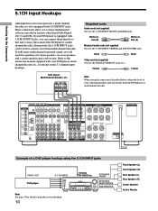
... - CENTER + - R PRE OUT IMPEDANCE USE 4-16Ω R REAR L CENTER + R L REAR - Hooking Up the Components 5.1CH Input Hookups Although this receiver incorporates a multi channel decoder, it is equipped with 5.1CH OUTPUT jacks, you can be used to the instruction manual supplied with your surround speakers and sub woofer from the DVD player or multichannel decoder. Alternatively, the 5.1CH INPUT jacks can connect them directly to this unit to enjoy the sound of your DVD player, multi channel decoder, etc., for details on the 5.1 channel input hookups. Refer to connect...
... - CENTER + - R PRE OUT IMPEDANCE USE 4-16Ω R REAR L CENTER + R L REAR - Hooking Up the Components 5.1CH Input Hookups Although this receiver incorporates a multi channel decoder, it is equipped with 5.1CH OUTPUT jacks, you can be used to the instruction manual supplied with your surround speakers and sub woofer from the DVD player or multichannel decoder. Alternatively, the 5.1CH INPUT jacks can connect them directly to this unit to enjoy the sound of your DVD player, multi channel decoder, etc., for details on the 5.1 channel input hookups. Refer to connect...
Operating Instructions
Page 12
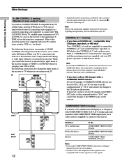
...'s COMMAND MODE selector can control from the receiver to an MD deck that is an example of S-LINK CONTROL S hookups between the receiver, a TV, a VCR, and a DVD player. Other Hookups Hooking Up the Components S-LINK CONTROL S hookup (Models of area code UC only) If you have a S-LINK CONTROL S-compatible Sony TV, satellite tuner, monitor, DVD player or VCR, use a video cord (not supplied) to connect to the appropriate SLINK jack on the respective component. Refer to the instructions supplied...
...'s COMMAND MODE selector can control from the receiver to an MD deck that is an example of S-LINK CONTROL S hookups between the receiver, a TV, a VCR, and a DVD player. Other Hookups Hooking Up the Components S-LINK CONTROL S hookup (Models of area code UC only) If you have a S-LINK CONTROL S-compatible Sony TV, satellite tuner, monitor, DVD player or VCR, use a video cord (not supplied) to connect to the appropriate SLINK jack on the respective component. Refer to the instructions supplied...

Operating Instructions
Page 13
.... If you turn the receiver on the receiver, the receiver will be cleared. 13 Do not connect high-wattage electrical home appliances such as electric irons, fans, or TVs to this receiver to a wall outlet: • Connect the speaker system to the receiver (see page 15). • Turn the MASTER VOLUME control to the leftmost position (0). Hooking Up the Components Setting the voltage selector If your audio/video components to...
.... If you turn the receiver on the receiver, the receiver will be cleared. 13 Do not connect high-wattage electrical home appliances such as electric irons, fans, or TVs to this receiver to a wall outlet: • Connect the speaker system to the receiver (see page 15). • Turn the MASTER VOLUME control to the leftmost position (0). Hooking Up the Components Setting the voltage selector If your audio/video components to...
Operating Instructions
Page 17
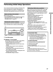
.... Hooking Up and Setting Up the Speaker System Performing Initial Setup Operations Once you have : • Turned MASTER VOLUME to turn on page 28). Then specify the speaker parameters (size, position, etc.) and perform any other components will clear the receiver's memory. The currently selected function appears in the display twice: "Now Demonstration Mode!! You can adjust the following items are reset or cleared: • All preset stations are reset or...
.... Hooking Up and Setting Up the Speaker System Performing Initial Setup Operations Once you have : • Turned MASTER VOLUME to turn on page 28). Then specify the speaker parameters (size, position, etc.) and perform any other components will clear the receiver's memory. The currently selected function appears in the display twice: "Now Demonstration Mode!! You can adjust the following items are reset or cleared: • All preset stations are reset or...
Operating Instructions
Page 22
x Rear L/R speaker crossover frequency (REAR L/R SP >) Initial setting : STD (=120 Hz) Lets you adjust the rear L/R speaker bass crossover frequency when the rear L/R speakers are set to STD. x Distance unit (DIST. buttons on the remote. • To adjust the volume level of the rear center speaker, use the rear center level parameter in the LEVEL menu (see page 38). • To adjust the volume level of the sub woofer, use the sub woofer level parameter in the LEVEL menu (see page 38). 4 Press TEST TONE again to turn on the receiver. 2 Press TEST TONE on the remote. •...
x Rear L/R speaker crossover frequency (REAR L/R SP >) Initial setting : STD (=120 Hz) Lets you adjust the rear L/R speaker bass crossover frequency when the rear L/R speakers are set to STD. x Distance unit (DIST. buttons on the remote. • To adjust the volume level of the rear center speaker, use the rear center level parameter in the LEVEL menu (see page 38). • To adjust the volume level of the sub woofer, use the sub woofer level parameter in the LEVEL menu (see page 38). 4 Press TEST TONE again to turn on the receiver. 2 Press TEST TONE on the remote. •...
Operating Instructions
Page 23
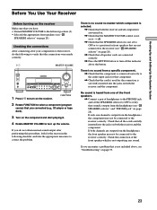
... all components are turned on. , Check that the MASTER VOLUME control is not set at -∞ dB. , Check that the SPEAKERS selector is not set the SPEAKERS selector to OFF to verify that sound is output from a specific component. , Check that the component is connected correctly to turn off the indicator above , see "Troubleshooting" on the component and start playing it. 4 Rotate MASTER VOLUME to the audio input jacks for that component. , Check that the cord(s) used...
... all components are turned on. , Check that the MASTER VOLUME control is not set at -∞ dB. , Check that the SPEAKERS selector is not set the SPEAKERS selector to OFF to verify that sound is output from a specific component. , Check that the component is connected correctly to turn off the indicator above , see "Troubleshooting" on the component and start playing it. 4 Rotate MASTER VOLUME to the audio input jacks for that component. , Check that the cord(s) used...

Operating Instructions
Page 25
... component you selected. 8 765 4 6 AUDIO SPLIT button Press to the 5.1CH INPUT jacks. Press 5.1 CH again to return to use. CINEMA STUDIO EX. - However, if you want to the original function. • When 5.1CH INPUT is convenient when you selected and play the program source. • After selecting VCR, camcorder, video game, DVD player, or LD player, turn on the component you are using a number of Parts and Basic Amplifier Operations 1 1/u SPEAKERS OFF A B A+B PHONES 23 MASTER VOLUME 5 4 6 3 7 MULTI CHANNEL DECODING 2 8 DISPLAY FM / AM PRESET...
... component you selected. 8 765 4 6 AUDIO SPLIT button Press to the 5.1CH INPUT jacks. Press 5.1 CH again to return to use. CINEMA STUDIO EX. - However, if you want to the original function. • When 5.1CH INPUT is convenient when you selected and play the program source. • After selecting VCR, camcorder, video game, DVD player, or LD player, turn on the component you are using a number of Parts and Basic Amplifier Operations 1 1/u SPEAKERS OFF A B A+B PHONES 23 MASTER VOLUME 5 4 6 3 7 MULTI CHANNEL DECODING 2 8 DISPLAY FM / AM PRESET...

Operating Instructions
Page 27
... speaker setup parameter. Digital Power Management Specify whether or not the system turns off when selected using the function buttons (page 55). 2 Way Remote Turn on -screen display (page 56). * Only when the speaker is set 2ND AV to "SOURCE", the analog audio signals of the assigned audio (for models (page 56). Auto Function Specify whether or not Sony components connected via control A1 cords will turn on or off the power of the monitor (Except for example, analog audio input of the following parameters. "SOURCE" selects...
... speaker setup parameter. Digital Power Management Specify whether or not the system turns off when selected using the function buttons (page 55). 2 Way Remote Turn on -screen display (page 56). * Only when the speaker is set 2ND AV to "SOURCE", the analog audio signals of the assigned audio (for models (page 56). Auto Function Specify whether or not Sony components connected via control A1 cords will turn on or off the power of the monitor (Except for example, analog audio input of the following parameters. "SOURCE" selects...

Operating Instructions
Page 28
... the button lights up and you can adjust the various surround parameters (effect level, wall type, etc.). RDS/EON button Press to set the IMPEDANCE SELECTOR to connect front speakers with 96 kHz digital audio signals. Models of front speakers. The indicator on -screen display. Selecting other area codes TUNING +/- For details, see "Receiving Broadcasts" starting from the headphones. wk The following buttons operate the built-in tuner. MEMORY button Press to activate the equalizer parameters...
... the button lights up and you can adjust the various surround parameters (effect level, wall type, etc.). RDS/EON button Press to set the IMPEDANCE SELECTOR to connect front speakers with 96 kHz digital audio signals. Models of front speakers. The indicator on -screen display. Selecting other area codes TUNING +/- For details, see "Receiving Broadcasts" starting from the headphones. wk The following buttons operate the built-in tuner. MEMORY button Press to activate the equalizer parameters...

Operating Instructions
Page 36
... frequencies to alter the sonic character of your listening environment by making new adjustments to "AUTO", the receiver performs PRO LOGIC decoding if Dolby surround encoded flag is selected. This parameter lets you enjoy the appropriate surround sound from the rear channels. • When set to suit your speakers and do the procedures described in each sound field. 1 Start playing a program source encoded with multi channel surround sound. 2 Press SURROUND. Adjusting the surround parameters The SURROUND menu...
... frequencies to alter the sonic character of your listening environment by making new adjustments to "AUTO", the receiver performs PRO LOGIC decoding if Dolby surround encoded flag is selected. This parameter lets you enjoy the appropriate surround sound from the rear channels. • When set to suit your speakers and do the procedures described in each sound field. 1 Start playing a program source encoded with multi channel surround sound. 2 Press SURROUND. Adjusting the surround parameters The SURROUND menu...

Operating Instructions
Page 39
... to watch movies at low volumes late at low volumes. Therefore, we recommend using 0.1~0.9. Front speaker midrange adjustment (Gain/ Frequency) Adjust as described in 1 dB steps from +10 dB to compress the dynamic range of the front, center, rear L/R and rear center speakers individually. However, the low frequency sounds of the equalizers (EQ 1 ~ 5). 1 Start playing a program source encoded with multi channel surround sound. 2 Press EQ. The following menu is displayed. Press the EQ BANK button repeatedly until you achieve...
... to watch movies at low volumes late at low volumes. Therefore, we recommend using 0.1~0.9. Front speaker midrange adjustment (Gain/ Frequency) Adjust as described in 1 dB steps from +10 dB to compress the dynamic range of the front, center, rear L/R and rear center speakers individually. However, the low frequency sounds of the equalizers (EQ 1 ~ 5). 1 Start playing a program source encoded with multi channel surround sound. 2 Press EQ. The following menu is displayed. Press the EQ BANK button repeatedly until you achieve...

Operating Instructions
Page 40
... specific adjustments. Resetting customized sound fields to the factory settings 1 If the power is on, press ?/1 to 10.0 kHz in 37 steps. 40 Rear L/R speaker midrange bandwidth This parammeter lets you adjust the width of the midrange band. • "WIDE" provides a wide band centered on the selected frequency, for general adjustments. • "MIDDLE" provides a normal band. • "NARROW" provides a narrowband centered on the selected frequency, for specific adjustments. Rear L/R speaker bass adjustment (Gain/ Frequency) Adjust...
... specific adjustments. Resetting customized sound fields to the factory settings 1 If the power is on, press ?/1 to 10.0 kHz in 37 steps. 40 Rear L/R speaker midrange bandwidth This parammeter lets you adjust the width of the midrange band. • "WIDE" provides a wide band centered on the selected frequency, for general adjustments. • "MIDDLE" provides a normal band. • "NARROW" provides a narrowband centered on the selected frequency, for specific adjustments. Rear L/R speaker bass adjustment (Gain/ Frequency) Adjust...
Operating Instructions
Page 53
... a digital audio signal, connect a digital component to create an index name for example, MD/DAT ANALOG) is output. • When 5.1CH INPUT is cut off to the analog TAPE OUT or MD/DAT OUT jacks. To index a program source Select the program source (component) to be changed flashes, then turn the jog dial to assign a digital audio input (for each component. If you are not output from REC OUT jacks. • No signals output from the REC OUT jacks. If you select ANALOG DIRECT...
... a digital audio signal, connect a digital component to create an index name for example, MD/DAT ANALOG) is output. • When 5.1CH INPUT is cut off to the analog TAPE OUT or MD/DAT OUT jacks. To index a program source Select the program source (component) to be changed flashes, then turn the jog dial to assign a digital audio input (for each component. If you are not output from REC OUT jacks. • No signals output from the REC OUT jacks. If you select ANALOG DIRECT...
Operating Instructions
Page 60
... a digital component, make sure the input mode is set to ANALOG (see page 24) before recording with automatic tuning). The surround effect cannot be interrupted. Use direct tuning. , Make sure you want the current program to be obtained. , Make sure the sound field function is on (press MODE +/-). , Make sure that the antennas are connected correctly. , Select the source component by another station or the receiver automatically starts scanning stations.* , The EON function is...
... a digital component, make sure the input mode is set to ANALOG (see page 24) before recording with automatic tuning). The surround effect cannot be interrupted. Use direct tuning. , Make sure you want the current program to be obtained. , Make sure the sound field function is on (press MODE +/-). , Make sure that the antennas are connected correctly. , Select the source component by another station or the receiver automatically starts scanning stations.* , The EON function is...

Operating Instructions
Page 68
... input 10 AC power cord 13 antennas 5 audio components 6 digital components 8, 9 CONTROL A1 II 12 S-LINK CONTROL S 12 speaker system 15 video components 7 I, J, K Indexing. See Preset tuning radio stations. See Naming L, M Labeling. See Dolby Digital (AC-3) Adjusting brightness of the display 28 equalizer 39 speaker volumes 22 surround parameters 36 Autobetical 46 Automatic tuning 47 B Basic operations 24~28 Battery 4 C Changing display 26 effect level 36 Checking the connections 23 Clearing receiver's memory 17 Color system 56 Connecting 4~13 Crossover frequency 22 Customizing sound...
... input 10 AC power cord 13 antennas 5 audio components 6 digital components 8, 9 CONTROL A1 II 12 S-LINK CONTROL S 12 speaker system 15 video components 7 I, J, K Indexing. See Preset tuning radio stations. See Naming L, M Labeling. See Dolby Digital (AC-3) Adjusting brightness of the display 28 equalizer 39 speaker volumes 22 surround parameters 36 Autobetical 46 Automatic tuning 47 B Basic operations 24~28 Battery 4 C Changing display 26 effect level 36 Checking the connections 23 Clearing receiver's memory 17 Color system 56 Connecting 4~13 Crossover frequency 22 Customizing sound...


