
Operating Instructions (primary manual)
Page 6
...) White (L) Red (R) B Audio/video cord (not supplied) Yellow (video) White (L/audio) Red (R/audio) C Video cord (not supplied) Yellow (video) D Optical digital cord (not supplied) Black E Coaxial digital cord (supplied) Orange F Monaural audio cord (not supplied) Black White (L) Red (R) Yellow (video) White (L/audio...) Red (R/audio) Yellow (video) Black Orange Black Before you connect optical digital cords, insert the cord plugs straight in until all of the connections are completed. • Be sure to make connections firmly to...
...) White (L) Red (R) B Audio/video cord (not supplied) Yellow (video) White (L/audio) Red (R/audio) C Video cord (not supplied) Yellow (video) D Optical digital cord (not supplied) Black E Coaxial digital cord (supplied) Orange F Monaural audio cord (not supplied) Black White (L) Red (R) Yellow (video) White (L/audio...) Red (R/audio) Yellow (video) Black Orange Black Before you connect optical digital cords, insert the cord plugs straight in until all of the connections are completed. • Be sure to make connections firmly to...
Operating Instructions (primary manual)
Page 7
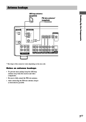
Hooking Up the Components Antenna hookups AM loop antenna (supplied) FM wire antenna* (supplied) DIGITAL OPTICAL VIDEO 2 IN ANTENNA AM MONITOR DVD/LD IN COAXIAL FM 75Ω COAXIAL VIDEO IN VIDEO IN VIDEO OUT VIDEO IN VIDEO OUT L CENTER R SUB FRONT SURROUND WOOFER MULTI CH IN AUDIO OUT L ... depending on antenna hookups • To prevent noise pickup, keep the AM loop antenna away from the receiver and other components. • Be sure to fully extend the FM wire antenna. • After connecting the FM wire antenna, keep it as horizontal as possible. 7GB Notes on the area code.
Hooking Up the Components Antenna hookups AM loop antenna (supplied) FM wire antenna* (supplied) DIGITAL OPTICAL VIDEO 2 IN ANTENNA AM MONITOR DVD/LD IN COAXIAL FM 75Ω COAXIAL VIDEO IN VIDEO IN VIDEO OUT VIDEO IN VIDEO OUT L CENTER R SUB FRONT SURROUND WOOFER MULTI CH IN AUDIO OUT L ... depending on antenna hookups • To prevent noise pickup, keep the AM loop antenna away from the receiver and other components. • Be sure to fully extend the FM wire antenna. • After connecting the FM wire antenna, keep it as horizontal as possible. 7GB Notes on the area code.
Operating Instructions (primary manual)
Page 8
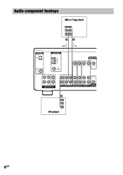
Audio component hookups DIGITAL OPTICAL VIDEO 2 IN MD or Tape deck INPUT OUTPUT LINE LINE L R A A ç ç OUT IN ANTENNA AM MONITOR DVD/LD IN COAXIAL FM 75Ω COAXIAL VIDEO IN VIDEO IN VIDEO OUT VIDEO IN VIDEO OUT L CENTER R SUB FRONT SURROUND WOOFER MULTI CH IN AUDIO OUT L R IN CD OUT IN AUDIO IN AUDIO IN AUDIO OUT AUDIO IN SUB MD/TAPE DVD/LD VIDEO 2 VIDEO 1 WOOFER A OUTPUT LINE L R CD player 8GB
Audio component hookups DIGITAL OPTICAL VIDEO 2 IN MD or Tape deck INPUT OUTPUT LINE LINE L R A A ç ç OUT IN ANTENNA AM MONITOR DVD/LD IN COAXIAL FM 75Ω COAXIAL VIDEO IN VIDEO IN VIDEO OUT VIDEO IN VIDEO OUT L CENTER R SUB FRONT SURROUND WOOFER MULTI CH IN AUDIO OUT L R IN CD OUT IN AUDIO IN AUDIO IN AUDIO OUT AUDIO IN SUB MD/TAPE DVD/LD VIDEO 2 VIDEO 1 WOOFER A OUTPUT LINE L R CD player 8GB
Operating Instructions (primary manual)
Page 9
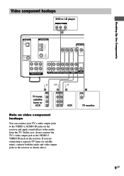
... apply sound effects to the audio from the TV. In this case, do not connect the TV's video output jack to the receiver as shown above. C INPUT VIDEO IN TV monitor 9GB Hooking Up the Components Ç Ç Video component hookups DVD or LD player OUTPUT AUDIO OUT R L ...VIDEO OUT B DIGITAL OPTICAL VIDEO 2 IN ANTENNA AM MONITOR DVD/LD IN COAXIAL FM 75Ω COAXIAL VIDEO IN VIDEO IN VIDEO OUT VIDEO IN VIDEO OUT L CENTER R SUB FRONT SURROUND WOOFER MULTI CH IN...
... apply sound effects to the audio from the TV. In this case, do not connect the TV's video output jack to the receiver as shown above. C INPUT VIDEO IN TV monitor 9GB Hooking Up the Components Ç Ç Video component hookups DVD or LD player OUTPUT AUDIO OUT R L ...VIDEO OUT B DIGITAL OPTICAL VIDEO 2 IN ANTENNA AM MONITOR DVD/LD IN COAXIAL FM 75Ω COAXIAL VIDEO IN VIDEO IN VIDEO OUT VIDEO IN VIDEO OUT L CENTER R SUB FRONT SURROUND WOOFER MULTI CH IN...
Operating Instructions (primary manual)
Page 10
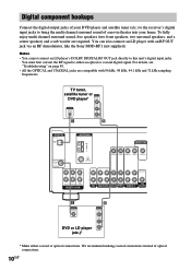
...instead of a movie theater into your home. For details, see "Troubleshooting" on page 50. • All the OPTICAL and COAXIAL jacks are required. To fully enjoy multi channel surround sound, five speakers (two front speakers, two surround ..., like the Sony MOD-RF1 (not supplied). TV tuner, satellite tuner or OUTPUT DVD player* VIDEO OUT OUTPUT DIGITAL OPTICAL AUDIO OUT L R D B DIGITAL OPTICAL VIDEO 2 IN ANTENNA AM MONITOR DVD/LD IN COAXIAL FM 75Ω ...your DVD player and satellite tuner (etc.) to the receiver's digital input jacks to bring the multi channel surround sound of...
...instead of a movie theater into your home. For details, see "Troubleshooting" on page 50. • All the OPTICAL and COAXIAL jacks are required. To fully enjoy multi channel surround sound, five speakers (two front speakers, two surround ..., like the Sony MOD-RF1 (not supplied). TV tuner, satellite tuner or OUTPUT DVD player* VIDEO OUT OUTPUT DIGITAL OPTICAL AUDIO OUT L R D B DIGITAL OPTICAL VIDEO 2 IN ANTENNA AM MONITOR DVD/LD IN COAXIAL FM 75Ω ...your DVD player and satellite tuner (etc.) to the receiver's digital input jacks to bring the multi channel surround sound of...
Operating Instructions (primary manual)
Page 11
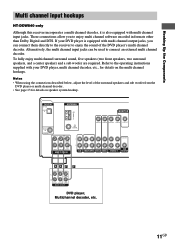
... to the operating instructions supplied with multi channel output jacks, you to connect an external multi channel decoder. DIGITAL OPTICAL VIDEO 2 IN ANTENNA AM MONITOR DVD/LD IN COAXIAL FM 75Ω COAXIAL VIDEO IN VIDEO IN VIDEO OUT VIDEO IN VIDEO OUT L CENTER R SUB FRONT SURROUND WOOFER..., and a center speaker) and a sub woofer are required. Hooking Up the Components Multi channel input hookups HT-DDW840 only Although this receiver incorporates a multi channel decoder, it is equipped with your DVD player, multi channel decoder, etc., for details on the multi channel hookups.
... to the operating instructions supplied with multi channel output jacks, you to connect an external multi channel decoder. DIGITAL OPTICAL VIDEO 2 IN ANTENNA AM MONITOR DVD/LD IN COAXIAL FM 75Ω COAXIAL VIDEO IN VIDEO IN VIDEO OUT VIDEO IN VIDEO OUT L CENTER R SUB FRONT SURROUND WOOFER..., and a center speaker) and a sub woofer are required. Hooking Up the Components Multi channel input hookups HT-DDW840 only Although this receiver incorporates a multi channel decoder, it is equipped with your DVD player, multi channel decoder, etc., for details on the multi channel hookups.
Operating Instructions (primary manual)
Page 22
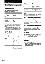
... signals recorded in a multi channel format. MULTI CH IN (HT-DDW840 only) Press MULTI CH IN to enjoy the audio source connected to the DIGITAL OPTICAL input jacks. MULTI CHANNEL DECODING indicator (HT-DDW840 only) This indicator lights up when the unit is canceled when you turn the power on or...
... signals recorded in a multi channel format. MULTI CH IN (HT-DDW840 only) Press MULTI CH IN to enjoy the audio source connected to the DIGITAL OPTICAL input jacks. MULTI CHANNEL DECODING indicator (HT-DDW840 only) This indicator lights up when the unit is canceled when you turn the power on or...

Operating Instructions (primary manual)
Page 27
.... Enjoying Surround Sound Understanding the multi channel surround displays qa qs 1 2 34 5 a DIGITAL PRO LOGIC DTS MPEG STEREO MONO RDS SW SP. Note Pro Logic decoding does not function for tuner operations. LCR SL SR continued 27GB DIGITAL: Lights ... 7 6 MEMORY 0 9 1 ; is a digital signal being input through the OPTICAL terminal. 9 Playback channel indicators: The letters (L, C, R, etc.) indicate the channels being input through the COAXIAL terminal. 8 OPT: Lights up when the receiver applies Pro Logic processing to adjust the dynamic range compression. 7 COAX: Lights up when...
.... Enjoying Surround Sound Understanding the multi channel surround displays qa qs 1 2 34 5 a DIGITAL PRO LOGIC DTS MPEG STEREO MONO RDS SW SP. Note Pro Logic decoding does not function for tuner operations. LCR SL SR continued 27GB DIGITAL: Lights ... 7 6 MEMORY 0 9 1 ; is a digital signal being input through the OPTICAL terminal. 9 Playback channel indicators: The letters (L, C, R, etc.) indicate the channels being input through the COAXIAL terminal. 8 OPT: Lights up when the receiver applies Pro Logic processing to adjust the dynamic range compression. 7 COAX: Lights up when...
Operating Instructions (primary manual)
Page 51
...or reversed. • Check that the connecting cords are output from the headphones, the front speaker may not be connected to the receiver correctly. Wipe them with a cloth slightly moistened with function button. • Make sure that INPUT MODE is not reproduced. •...Connect the LD player to the RF demodulator, then connect the RF demodulator's optical or coaxial digital output to the receiver correctly. The receiver may not be connected to the receiver's jack. When making this receiver, check the audio setting (settings for the connection is recorded in the LEVEL...
...or reversed. • Check that the connecting cords are output from the headphones, the front speaker may not be connected to the receiver correctly. Wipe them with a cloth slightly moistened with function button. • Make sure that INPUT MODE is not reproduced. •...Connect the LD player to the RF demodulator, then connect the RF demodulator's optical or coaxial digital output to the receiver correctly. The receiver may not be connected to the receiver's jack. When making this receiver, check the audio setting (settings for the connection is recorded in the LEVEL...
Operating Instructions (primary manual)
Page 54
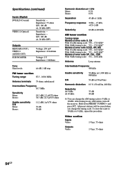
... Voltage: 2 V Impedance: 1 kilohms Tone Gain levels: ±6 dB, 1 dB step FM tuner section Tuning range 87.5 - 108.0 MHz Antenna terminals 75 ohms, unbalanced Intermediate Frequency 10.7 MHz Sensitivity Mono: Stereo: 18.3 dBf, 2.2 µV/75 ohms 38.3 dBf, 22.5 µV/75 ohms Usable ... 75 ohms 1 Vp-p, 75 ohms 54GB Specifications (continued) Inputs (Digital) DVD/LD (Coaxial) VIDEO 2 (Optical) Sensitivity: - After tuning in any AM station, turn off the receiver. Hold down PRESET TUNING + and press ?/1. Impedance: - All preset stations will be erased when you change the...
... Voltage: 2 V Impedance: 1 kilohms Tone Gain levels: ±6 dB, 1 dB step FM tuner section Tuning range 87.5 - 108.0 MHz Antenna terminals 75 ohms, unbalanced Intermediate Frequency 10.7 MHz Sensitivity Mono: Stereo: 18.3 dBf, 2.2 µV/75 ohms 38.3 dBf, 22.5 µV/75 ohms Usable ... 75 ohms 1 Vp-p, 75 ohms 54GB Specifications (continued) Inputs (Digital) DVD/LD (Coaxial) VIDEO 2 (Optical) Sensitivity: - After tuning in any AM station, turn off the receiver. Hold down PRESET TUNING + and press ?/1. Impedance: - All preset stations will be erased when you change the...


