
Operating Instructions
Page 3
Check your remote, see pages 25-27. For details on the receiver. Center speaker - Sub woofer STR-K665P SS-MSP66L SS-MSP66R SS-CNP66 SS-MSP66SL SS-MSP66SR SS-WMSP66 This receiver incorporates Dolby* Digital and Pro Logic Surround and the DTS** Digital Surround System. * Manufactured under ... front panel. • The instructions in this manual describe the controls on the receiver. Note for model HT-DDW665. About This Manual • The instructions in this manual are registered trademarks of Digital Theater Systems, Inc. Surround speaker (left ) - "Dolby", "Pro Logic" and the ...
Check your remote, see pages 25-27. For details on the receiver. Center speaker - Sub woofer STR-K665P SS-MSP66L SS-MSP66R SS-CNP66 SS-MSP66SL SS-MSP66SR SS-WMSP66 This receiver incorporates Dolby* Digital and Pro Logic Surround and the DTS** Digital Surround System. * Manufactured under ... front panel. • The instructions in this manual describe the controls on the receiver. Note for model HT-DDW665. About This Manual • The instructions in this manual are registered trademarks of Digital Theater Systems, Inc. Surround speaker (left ) - "Dolby", "Pro Logic" and the ...

Operating Instructions
Page 4
Table of Contents Getting Started 1: Connecting your remote 25 Remote button description 25 Additional Information Precautions 28 Troubleshooting 29 Specifications 31 List of button locations and reference pages 33 Index 34 4US ...INPUT MODE Customizing sound fields 20 Adjusting the tone 22 Advanced settings 22 Other Operations Naming preset stations and inputs ........ 24 Operations Using the Remote RM-U665 Before you use your components 5 2: Connecting the antennas 7 3: Connecting speakers 8 4: Connecting the AC power cord ........ 10 5: Setting up the speakers 11 ...
Table of Contents Getting Started 1: Connecting your remote 25 Remote button description 25 Additional Information Precautions 28 Troubleshooting 29 Specifications 31 List of button locations and reference pages 33 Index 34 4US ...INPUT MODE Customizing sound fields 20 Adjusting the tone 22 Advanced settings 22 Other Operations Naming preset stations and inputs ........ 24 Operations Using the Remote RM-U665 Before you use your components 5 2: Connecting the antennas 7 3: Connecting speakers 8 4: Connecting the AC power cord ........ 10 5: Setting up the speakers 11 ...

Operating Instructions
Page 6
Hooking up your DVD player and VCR For details on the required cords (A-C), see page 5. DIGITAL OPTICAL VIDEO IN B DVD IN COAXIAL ANTENNA AM L AUDIO IN R AUDIO IN DVD VIDEO A LINE IN 1 R AUDIO L VIDEO LINE IN OUT (FROM ANT.) OUT RF (TO TV) DVD Only LINE OUT COMPONENT VIDEO OUT L AUDIO R Pr Y DIGITAL AUDIO OUT S-VIDEO OUT OPTICAL Pb COAXIAL Note If you connect other components, use the remote and operating instructions supplied with the connected components for operation. 6US
Hooking up your DVD player and VCR For details on the required cords (A-C), see page 5. DIGITAL OPTICAL VIDEO IN B DVD IN COAXIAL ANTENNA AM L AUDIO IN R AUDIO IN DVD VIDEO A LINE IN 1 R AUDIO L VIDEO LINE IN OUT (FROM ANT.) OUT RF (TO TV) DVD Only LINE OUT COMPONENT VIDEO OUT L AUDIO R Pr Y DIGITAL AUDIO OUT S-VIDEO OUT OPTICAL Pb COAXIAL Note If you connect other components, use the remote and operating instructions supplied with the connected components for operation. 6US

Operating Instructions
Page 12
... A 30 • LOW Select if the height of the test tone sounds the same from each speaker. on the remote or turn on the LEVEL menu settings, see page 20. Tip The receiver employs a test tone with a frequency centered at the same time, press MASTER VOL +/- Front (left) t Center ...test tone is output from your listening position. Notes • Although these adjustments can also be made via the front panel using the remote. • The bass redirection circuitry is always active, so you follow the procedure described above and adjust the speaker levels from other ...
... A 30 • LOW Select if the height of the test tone sounds the same from each speaker. on the remote or turn on the LEVEL menu settings, see page 20. Tip The receiver employs a test tone with a frequency centered at the same time, press MASTER VOL +/- Front (left) t Center ...test tone is output from your listening position. Notes • Although these adjustments can also be made via the front panel using the remote. • The bass redirection circuitry is always active, so you follow the procedure described above and adjust the speaker levels from other ...

Operating Instructions
Page 13
... to FM and AM broadcasts through the built-in your speakers, make sure you do the following. • Press MUTING on the remote again. • Turn the power off the receiver. Tip The tuning scale is: FM: 100 kHz AM: 10 kHz* * The AM tuning scale can listen to monaural (MONO). ...input to match the component you turn down the volume before you selected. 3 Turn MASTER VOLUME -/+ to low. The receiver stops scanning whenever a station is tuned in the display. 2 Turn on the remote. To return to the PHONES jack. To select the Press VCR VIDEO DVD player DVD Built-in tuner (FM...
... to FM and AM broadcasts through the built-in your speakers, make sure you do the following. • Press MUTING on the remote again. • Turn the power off the receiver. Tip The tuning scale is: FM: 100 kHz AM: 10 kHz* * The AM tuning scale can listen to monaural (MONO). ...input to match the component you turn down the volume before you selected. 3 Turn MASTER VOLUME -/+ to low. The receiver stops scanning whenever a station is tuned in the display. 2 Turn on the remote. To return to the PHONES jack. To select the Press VCR VIDEO DVD player DVD Built-in tuner (FM...

Operating Instructions
Page 14
.... Presetting radio stations 1 Press FM or AM to select a preset number. 5 Press MEMORY again. Tip You can also use FM or AM on the receiver. 2 Press D.TUNING. 3 Press the numeric buttons to enter the last "0" when the tuning scale is not used in your area. Press SHIFT repeatedly to...preset using Automatic Tuning (page 13) or Direct Tuning (page 14). 3 Press MEMORY. The last received station is stored to select a preset station number. Each time you press the button, you can also use the remote to the selected preset number. If not, repeat steps 2 and 3. Then you can preset up...
.... Presetting radio stations 1 Press FM or AM to select a preset number. 5 Press MEMORY again. Tip You can also use FM or AM on the receiver. 2 Press D.TUNING. 3 Press the numeric buttons to enter the last "0" when the tuning scale is not used in your area. Press SHIFT repeatedly to...preset using Automatic Tuning (page 13) or Direct Tuning (page 14). 3 Press MEMORY. The last received station is stored to select a preset station number. Each time you press the button, you can also use the remote to the selected preset number. If not, repeat steps 2 and 3. Then you can preset up...

Operating Instructions
Page 15
...the display You can select the preset station as follows: tA1yA2y...yA0yB1yB2y...yB0T tC0y...yC2yC1T Using the remote 1 Press FM or AM to select the preset station you want . The brightness of the ...check the sound field etc. To select the preset station directly Press the numeric buttons on the remote to the input or preset station (page 24). The preset station of the display will change ... 1 Press FM or AM to select the preset station you want . Press SHIFT repeatedly on the remote. Index name does not appear when only blank spaces have assigned one to change in 3 steps. ...
...the display You can select the preset station as follows: tA1yA2y...yA0yB1yB2y...yB0T tC0y...yC2yC1T Using the remote 1 Press FM or AM to select the preset station you want . The brightness of the ...check the sound field etc. To select the preset station directly Press the numeric buttons on the remote to the input or preset station (page 24). The preset station of the display will change ... 1 Press FM or AM to select the preset station you want . Press SHIFT repeatedly on the remote. Index name does not appear when only blank spaces have assigned one to change in 3 steps. ...

Operating Instructions
Page 25
... qg qf qd from battery leakage and corrosion. properly oriented in the battery compartment. Remote Button A.F.D. When using the remote, point it at the remote sensor on the receiver. 1 2 3 4 5 SELECT DVD VIDEO SYSTEM STANDBY FM AM 2CH A.F.D. Before you don't use your system. ql Under normal conditions, the batteries should last for audio sound. Doing so...
... qg qf qd from battery leakage and corrosion. properly oriented in the battery compartment. Remote Button A.F.D. When using the remote, point it at the remote sensor on the receiver. 1 2 3 4 5 SELECT DVD VIDEO SYSTEM STANDBY FM AM 2CH A.F.D. Before you don't use your system. ql Under normal conditions, the batteries should last for audio sound. Doing so...
Operating Instructions
Page 26
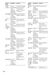
... RECORDER SYSTEM Receiver/TV/ Turns off . and CASSETTE ?/1 wl at RECORDER the same time) T.TONE wf Receiver Outputs test tone. 26US TRACKING VIDEO +/- DISPLAY 9 DVD PLAYER/ Selects information VIDEO displayed on or CASSETTE off the receiver STANDBY DVD PLAYER/ and other Sony audio/...from the receiver. MAIN Receiver MENU qf Selects the menu of the receiver. CASSETTE RECORDER SHIFT 6 Receiver Selects a memory page for movie and music. VIDEO CASSETTE RECORDER FM wk Receiver To select the FM band. Remote Button Operations Function AM wj Receiver To select...
... RECORDER SYSTEM Receiver/TV/ Turns off . and CASSETTE ?/1 wl at RECORDER the same time) T.TONE wf Receiver Outputs test tone. 26US TRACKING VIDEO +/- DISPLAY 9 DVD PLAYER/ Selects information VIDEO displayed on or CASSETTE off the receiver STANDBY DVD PLAYER/ and other Sony audio/...from the receiver. MAIN Receiver MENU qf Selects the menu of the receiver. CASSETTE RECORDER SHIFT 6 Receiver Selects a memory page for movie and music. VIDEO CASSETTE RECORDER FM wk Receiver To select the FM band. Remote Button Operations Function AM wj Receiver To select...

Operating Instructions
Page 27
.... TV qa Selects preset TV channels. WIDE qs TV Selects the wide picture mode. ?/1 wl Receiver Turns the receiver on or off . 2CH 3 Receiver Selects 2CH STEREO mode. B/b 9 Receiver Makes adjustment or change the setting. Adjusts the volume of the TV might not switch to serve... as an example only. VIDEO 2 Receiver To watch DVD PLAYER/VIDEO CASSETTE RECORDER (VIDEO mode). Other Operations/Operations Using the Remote RM-U665 Remote Button Operations Function TOP MENU VIDEO 9 CASSETTE RECORDER (DVD mode) Displays DVD title....
.... TV qa Selects preset TV channels. WIDE qs TV Selects the wide picture mode. ?/1 wl Receiver Turns the receiver on or off . 2CH 3 Receiver Selects 2CH STEREO mode. B/b 9 Receiver Makes adjustment or change the setting. Adjusts the volume of the TV might not switch to serve... as an example only. VIDEO 2 Receiver To watch DVD PLAYER/VIDEO CASSETTE RECORDER (VIDEO mode). Other Operations/Operations Using the Remote RM-U665 Remote Button Operations Function TOP MENU VIDEO 9 CASSETTE RECORDER (DVD mode) Displays DVD title....

Operating Instructions
Page 29
...or MUSIC). • Sound fields do not function for that component. • Check that MASTER VOLUME -/+ is (are dirty. There is on the receiver. continued 29US The left and right sounds are unbalanced or reversed. • Check that the headphones are connected correctly and securely. • Adjust balance ...away from analog 2 channel sources. • Check that the INPUT MODE is not reproduced. • Check that the INPUT MODE is on the remote to "COAX IN" or "OPT IN" (page 20). to the digital input jacks of the connected component. Dolby Digital or DTS multi channel...
...or MUSIC). • Sound fields do not function for that component. • Check that MASTER VOLUME -/+ is (are dirty. There is on the receiver. continued 29US The left and right sounds are unbalanced or reversed. • Check that the headphones are connected correctly and securely. • Adjust balance ...away from analog 2 channel sources. • Check that the INPUT MODE is not reproduced. • Check that the INPUT MODE is on the remote to "COAX IN" or "OPT IN" (page 20). to the digital input jacks of the connected component. Dolby Digital or DTS multi channel...

Operating Instructions
Page 30
...stations). To operate other components, press TOP MENU or AV MENU after a few seconds. If this problem persists, consult your nearest Sony dealer. 30US To prevent a gas explosion, do not connect the ground wire to an outdoor FM antenna as shown below. Error ... before pressing the buttons. • Before you connect the receiver to an outdoor antenna, ground it against lightning. The receiver will automatically turn on the receiver. • Remove any obstacles in the path between the remote and the receiver. • Replace all the batteries in AM stations with automatic...
...stations). To operate other components, press TOP MENU or AV MENU after a few seconds. If this problem persists, consult your nearest Sony dealer. 30US To prevent a gas explosion, do not connect the ground wire to an outdoor FM antenna as shown below. Error ... before pressing the buttons. • Before you connect the receiver to an outdoor antenna, ground it against lightning. The receiver will automatically turn on the receiver. • Remove any obstacles in the path between the remote and the receiver. • Replace all the batteries in AM stations with automatic...

Operating Instructions
Page 32
After tuning in any AM station, turn off the receiver. General Power requirements 120 V AC, 60 Hz Power ... speakers 0.8 kg (1 lb 13 oz) Surround speakers 0.6 kg (1 lb 6 oz) Sub woofer (SS-WMSP66) Speaker system Magnetically shielded Speaker unit 200 mm cone type Enclosure type Acoustically loaded bass reflex Dimension (w/h/d) (Approx.) 270 × 325...(2) Speaker connecting cord, short (3) Coaxial digital cord (1) Foot pads (speakers) (20) Foot pads (subwoofer) (4) Remote commander (1) R6 (size-AA) batteries (2) Speakers • Front speakers (2) • Center speaker (1) •...
After tuning in any AM station, turn off the receiver. General Power requirements 120 V AC, 60 Hz Power ... speakers 0.8 kg (1 lb 13 oz) Surround speakers 0.6 kg (1 lb 6 oz) Sub woofer (SS-WMSP66) Speaker system Magnetically shielded Speaker unit 200 mm cone type Enclosure type Acoustically loaded bass reflex Dimension (w/h/d) (Approx.) 270 × 325...(2) Speaker connecting cord, short (3) Coaxial digital cord (1) Foot pads (speakers) (20) Foot pads (subwoofer) (4) Remote commander (1) R6 (size-AA) batteries (2) Speakers • Front speakers (2) • Center speaker (1) •...

Service Manual
Page 5
... qk qj qh qg qf qd qs The tables below show the settings of each button. Remote Button Operations Function AM wj Receiver To select the AM band. STR-K665P Remote button description 1 2 3 4 5 6 7 8 9 ENTER q; qa TV ?/1 AV ?/1 ?/1 SELECT DVD VIDEO SYSTEM STANDBY FM AM 2CH A.F.D. ANT MOVIE/MUSIC T.TONE 1 2 4 5 AUDIO 3 CH/PRESET/ TRACKING 6 7 8 9 0/10 . CASSETTE RECORDER...
... qk qj qh qg qf qd qs The tables below show the settings of each button. Remote Button Operations Function AM wj Receiver To select the AM band. STR-K665P Remote button description 1 2 3 4 5 6 7 8 9 ENTER q; qa TV ?/1 AV ?/1 ?/1 SELECT DVD VIDEO SYSTEM STANDBY FM AM 2CH A.F.D. ANT MOVIE/MUSIC T.TONE 1 2 4 5 AUDIO 3 CH/PRESET/ TRACKING 6 7 8 9 0/10 . CASSETTE RECORDER...
Service Manual
Page 6
...STR-K665P Remote Button Operations Function ENTER/12 w; MASTER Receiver VOL +/- MUTING Receiver qj Mutes the sound from the receiver. CASSETTE RECORDER SHIFT 6 Receiver...Receiver To select the FM band. qh Adjusts the master volume of the TV. CASSETTE RECORDER SYSTEM Receiver/TV/ Turns off . 2CH 3 Receiver Selects 2CH STEREO mode. TV VOL TV +/- DVD PLAYER/ Enters the selection. Remote...TV on or off the receiver STANDBY DVD PLAYER/ and other Sony audio/ (Press AV VIDEO video components. ?/1 e; V/v 9 Receiver Selects a menu item. B/b 9 Receiver Makes adjustment or change ...
...STR-K665P Remote Button Operations Function ENTER/12 w; MASTER Receiver VOL +/- MUTING Receiver qj Mutes the sound from the receiver. CASSETTE RECORDER SHIFT 6 Receiver...Receiver To select the FM band. qh Adjusts the master volume of the TV. CASSETTE RECORDER SYSTEM Receiver/TV/ Turns off . 2CH 3 Receiver Selects 2CH STEREO mode. TV VOL TV +/- DVD PLAYER/ Enters the selection. Remote...TV on or off the receiver STANDBY DVD PLAYER/ and other Sony audio/ (Press AV VIDEO video components. ?/1 e; V/v 9 Receiver Selects a menu item. B/b 9 Receiver Makes adjustment or change ...

Service Manual
Page 7
STR-K665P 7 Therefore, depending on the component the above explanation is not available. VIDEO CASSETTE RECORDER Notes • The above operation may not be possible or may ... input buttons (VIDEO or DVD), the input mode of the TV. • The >10/11 is intended to the corresponding input mode that you want. Remote Operations Function Button ./> DVD PLAYER/ Skips tracks. 6 VIDEO CASSETTE RECORDER m/M ql DVD PLAYER/ Searches tracks in recording standby.) x qk DVD PLAYER/ Stops playback. In this...
STR-K665P 7 Therefore, depending on the component the above explanation is not available. VIDEO CASSETTE RECORDER Notes • The above operation may not be possible or may ... input buttons (VIDEO or DVD), the input mode of the TV. • The >10/11 is intended to the corresponding input mode that you want. Remote Operations Function Button ./> DVD PLAYER/ Skips tracks. 6 VIDEO CASSETTE RECORDER m/M ql DVD PLAYER/ Searches tracks in recording standby.) x qk DVD PLAYER/ Stops playback. In this...

Service Manual
Page 8
... segments are reset to turn on the main power. CLR." Every pressing of repair. 8 Press the VIDEO button, confirm display. Every pressing of the remote commander can be selected. • Procedure: 1. The message "FACTORY" appears and the present contents are tested. SW LFE D D SP A D ... . 2. D. , MOVIE and MUSIC LED turn on the main power. SBL SBR MHz 2CH and MOVIE LED turn on the main power. 2. STR-K665P SECTION 2 TEST MODE FACTORY PRESET MODE • All preset contents are not counted again. AM CHANNEL STEP 9 KHz/10 KHz SELECTION MODE •...
... segments are reset to turn on the main power. CLR." Every pressing of repair. 8 Press the VIDEO button, confirm display. Every pressing of the remote commander can be selected. • Procedure: 1. The message "FACTORY" appears and the present contents are tested. SW LFE D D SP A D ... . 2. D. , MOVIE and MUSIC LED turn on the main power. SBL SBR MHz 2CH and MOVIE LED turn on the main power. 2. STR-K665P SECTION 2 TEST MODE FACTORY PRESET MODE • All preset contents are not counted again. AM CHANNEL STEP 9 KHz/10 KHz SELECTION MODE •...
Service Manual
Page 11
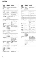
STR-K665P • R-CH is omitted due to same as L-CH L • Signal Path : FM SL A MAIN SECTION C FL101 FLUORESCENT INDICATOR TUBE SW F1 14 29 F2 ... 61 62 63 FL_STB HEADPHONE RELAY PREOUT/FRONT RELAY REAR RELAY CENTER RELAY PROTECTOR 67 71 69 70 66 SYSTEM CONTROL IC1601(3/3) HP DETECT 25 FUSE DETECT 55 SIRCS 54 IC102 REMOTE 1 CONTROL RECEIVER +3.3V AUDIO +5V FL101 -30V Q801 -30V REG Q471 +3.3V REG IC1503 3 +5V REG 1 RELAY +B AUDIO +7V AUDIO -7V...
STR-K665P • R-CH is omitted due to same as L-CH L • Signal Path : FM SL A MAIN SECTION C FL101 FLUORESCENT INDICATOR TUBE SW F1 14 29 F2 ... 61 62 63 FL_STB HEADPHONE RELAY PREOUT/FRONT RELAY REAR RELAY CENTER RELAY PROTECTOR 67 71 69 70 66 SYSTEM CONTROL IC1601(3/3) HP DETECT 25 FUSE DETECT 55 SIRCS 54 IC102 REMOTE 1 CONTROL RECEIVER +3.3V AUDIO +5V FL101 -30V Q801 -30V REG Q471 +3.3V REG IC1503 3 +5V REG 1 RELAY +B AUDIO +7V AUDIO -7V...
Service Manual
Page 28
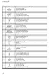
STR-K665P Pin No. Pin Name I/O 51 MD2 I 52 RDS CLOCK I 53 RDS DATA I 54 SIRCS I 55 FUSE DETECT I ... input RDS clock signal input (Not used) RDS data signal input (Not used) Data signal input from the remote control sensor Fuse detect signal input Power switch key detect signal input Jog dial signal input from the rotary encoder ...Stereo tuning signal input from the tuner Muting signal output to the tuner Frequency data signal input from the tuner System reset Latch signal output to the tuner Not used Ground terminal Ground terminal Connection for a crystal resonator Connection ...
STR-K665P Pin No. Pin Name I/O 51 MD2 I 52 RDS CLOCK I 53 RDS DATA I 54 SIRCS I 55 FUSE DETECT I ... input RDS clock signal input (Not used) RDS data signal input (Not used) Data signal input from the remote control sensor Fuse detect signal input Power switch key detect signal input Jog dial signal input from the rotary encoder ...Stereo tuning signal input from the tuner Muting signal output to the tuner Frequency data signal input from the tuner System reset Latch signal output to the tuner Not used Ground terminal Ground terminal Connection for a crystal resonator Connection ...


