
Limited Warranty (US Only)
Page 1
... will do not allow the exclusion or limitation of the Sony product. It is your unit. This Limited Warranty does not cover Sony products sold AS IS or WITH ALL FAULTS or consumables (such as set forth below is invalid if the factory-applied serial number ...product. 4-557-173-03 General Stereo/Hifi Components/Tape Decks ® CD Players/Mini Disc Players/Audio Systems Hifi Audio LIMITED WARRANTY (U.S. This Limited Warranty is still in material or workmanship during service and Sony will , at its original specifications. Some states do so for your exclusive remedies.
... will do not allow the exclusion or limitation of the Sony product. It is your unit. This Limited Warranty does not cover Sony products sold AS IS or WITH ALL FAULTS or consumables (such as set forth below is invalid if the factory-applied serial number ...product. 4-557-173-03 General Stereo/Hifi Components/Tape Decks ® CD Players/Mini Disc Players/Audio Systems Hifi Audio LIMITED WARRANTY (U.S. This Limited Warranty is still in material or workmanship during service and Sony will , at its original specifications. Some states do so for your exclusive remedies.
Operating Instructions
Page 6
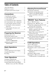
... TV 21 4a: Connecting the audio components.........23 4b: Connecting the video components ........24 5: Connecting the antennas (aerials 32 6: Inserting the wireless transmitter/ transceiver 32 7: Connecting the AC power cord (mains lead 33 Preparing the Receiver Initializing the receiver 34 Selecting the speaker system 34 Calibrating the appropriate speaker settings automatically (AUTO CALIBRATION 35 Adjusting...
... TV 21 4a: Connecting the audio components.........23 4b: Connecting the video components ........24 5: Connecting the antennas (aerials 32 6: Inserting the wireless transmitter/ transceiver 32 7: Connecting the AC power cord (mains lead 33 Preparing the Receiver Initializing the receiver 34 Selecting the speaker system 34 Calibrating the appropriate speaker settings automatically (AUTO CALIBRATION 35 Adjusting...

Operating Instructions
Page 7
Advanced Operations Switching between digital and analog audio (INPUT MODE 69 Enjoying the sound/images from other inputs 69 Enjoying sound/images from the components connected to the DIGITAL MEDIA PORT 71 Using a bi-amplifier connection 71 Using the setting menu 72 Supplied accessories • Operating instructions (this manual) • Quick Setup Guide...
Advanced Operations Switching between digital and analog audio (INPUT MODE 69 Enjoying the sound/images from other inputs 69 Enjoying sound/images from the components connected to the DIGITAL MEDIA PORT 71 Using a bi-amplifier connection 71 Using the setting menu 72 Supplied accessories • Operating instructions (this manual) • Quick Setup Guide...

Operating Instructions
Page 9
...-HD HI RES DTS-HD High Resolution Audio DTS-HD LBR DTS-HD Low Bit Rate Audio H S-AIR Lights up according to "AUTO" (page 69). Indicators on the speaker pattern setting. G DTS-HD indicators Lights up one of the respective indicators when the receiver is a digital signal being input through the COAXIAL jack (page...
...-HD HI RES DTS-HD High Resolution Audio DTS-HD LBR DTS-HD Low Bit Rate Audio H S-AIR Lights up according to "AUTO" (page 69). Indicators on the speaker pattern setting. G DTS-HD indicators Lights up one of the respective indicators when the receiver is a digital signal being input through the COAXIAL jack (page...

Operating Instructions
Page 10
... When playing a DTS format disc, be sure that you have made digital connections and that provides RDS services is set to show how the receiver downmixes or upmixes the source sound (based on the speaker settings). The boxes around the letters vary to "BI-AMP" (page 71). K SLEEP Lights up when the... receiver tunes in . LH RH L R C SL SR S SBL SBR SB Front Left High Front Right High Front Left Front Right Center (monaural) Surround Left Surround...
... When playing a DTS format disc, be sure that you have made digital connections and that provides RDS services is set to show how the receiver downmixes or upmixes the source sound (based on the speaker settings). The boxes around the letters vary to "BI-AMP" (page 71). K SLEEP Lights up when the... receiver tunes in . LH RH L R C SL SR S SBL SBR SB Front Left High Front Right High Front Left Front Right Center (monaural) Surround Left Surround...
Operating Instructions
Page 13
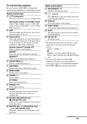
...Sony components. ENTERc) Enters the selection during tuner operation. I MENU/HOME Displays the receiver menus. N MUTING (RM-AAP049 only) (RM-AAP050 only) Turns off automatically. V SHIFT The button lights up and activates the receiver...STANDBY). Press again to the previous menu. number 5, VIDEO 1 -N - Name and function A ?/1b) (on/standby) Turns the receiver on the display. U NIGHT MODE Activates the Night ... the receiver. Y RM SET UP Set up the remote. Saving the power in standby mode When "CTRL: HDMI" is set to "CTRL OFF" (page 76) and "S-AIR STBY" is set to...
...Sony components. ENTERc) Enters the selection during tuner operation. I MENU/HOME Displays the receiver menus. N MUTING (RM-AAP049 only) (RM-AAP050 only) Turns off automatically. V SHIFT The button lights up and activates the receiver...STANDBY). Press again to the previous menu. number 5, VIDEO 1 -N - Name and function A ?/1b) (on/standby) Turns the receiver on the display. U NIGHT MODE Activates the Night ... the receiver. Y RM SET UP Set up the remote. Saving the power in standby mode When "CTRL: HDMI" is set to "CTRL OFF" (page 76) and "S-AIR STBY" is set to...

Operating Instructions
Page 14
...press the yellow printing button to select the function you connect a Sony TV that is compatible with the THEATER or THEATRE button function ... ?/1 (B) changes automatically each time you press ?/1 (A) and AV ?/1 (B) simultaneously, the receiver and connected components will turn off the TV. number 5, VIDEO 1 -N - The function of TV. , (Info, Text reveal) (RM-AAP050 only)...>10 Selects the channel entry mode. X THEATER (RM-AAP049 only) THEATRE (RM-AAP050 only) Sets the optimal picture settings automatically for watching movies when you want. M TV INPUT (RM-AAP049 only) (Input select)...
...press the yellow printing button to select the function you connect a Sony TV that is compatible with the THEATER or THEATRE button function ... ?/1 (B) changes automatically each time you press ?/1 (A) and AV ?/1 (B) simultaneously, the receiver and connected components will turn off the TV. number 5, VIDEO 1 -N - The function of TV. , (Info, Text reveal) (RM-AAP050 only)...>10 Selects the channel entry mode. X THEATER (RM-AAP049 only) THEATRE (RM-AAP050 only) Sets the optimal picture settings automatically for watching movies when you want. M TV INPUT (RM-AAP049 only) (Input select)...

Operating Instructions
Page 20
... back speaker or front high speakers, and you have made the bi-amplifier connection, set to on, it to L of this terminals. • If you are not touching... DC5V 0.7A MAX VIDEO IN VIDEO IN VIDEO OUT AUDIO IN AUDIO IN AUDIO IN AUDIO IN AUDIO OUT TV DIGITAL (ASSIGNABLE) IN OPTICAL SAT/ CATV IN OPTICAL VIDEO IN VIDEO OUT BD DVD IN IN COAXIAL AUDIO MONITOR IN AUDIO OUT SURROUND BACK/ FRONT...of the input signal to a subwoofer, then sound may cause a malfunction of the receiver. After you have an additional front speaker system, connect the additional front speaker system ...
... back speaker or front high speakers, and you have made the bi-amplifier connection, set to on, it to L of this terminals. • If you are not touching... DC5V 0.7A MAX VIDEO IN VIDEO IN VIDEO OUT AUDIO IN AUDIO IN AUDIO IN AUDIO IN AUDIO OUT TV DIGITAL (ASSIGNABLE) IN OPTICAL SAT/ CATV IN OPTICAL VIDEO IN VIDEO OUT BD DVD IN IN COAXIAL AUDIO MONITOR IN AUDIO OUT SURROUND BACK/ FRONT...of the input signal to a subwoofer, then sound may cause a malfunction of the receiver. After you have an additional front speaker system, connect the additional front speaker system ...
Operating Instructions
Page 21
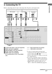
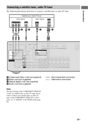
.... Be sure to the receiver, connect either C or E. Recommended connection Alternative connection a)To enjoy TV multi channel surround sound broadcasting from the speakers connected to "ARC ON" in HDMI menu (page 60). Video signals TV Audio signals Audio/Video signals A B Ca) ... SPEAKERS SURROUND R L FRONT A R L A Component video cord (not supplied) B Video cord (not supplied) C Optical digital cord (not supplied) D Audio cord (not supplied) E HDMI cable (not supplied) We recommend that you use a Sony HDMI cable. Connections 3: Connecting the TV Before connecting cords...
.... Be sure to the receiver, connect either C or E. Recommended connection Alternative connection a)To enjoy TV multi channel surround sound broadcasting from the speakers connected to "ARC ON" in HDMI menu (page 60). Video signals TV Audio signals Audio/Video signals A B Ca) ... SPEAKERS SURROUND R L FRONT A R L A Component video cord (not supplied) B Video cord (not supplied) C Optical digital cord (not supplied) D Audio cord (not supplied) E HDMI cable (not supplied) We recommend that you use a Sony HDMI cable. Connections 3: Connecting the TV Before connecting cords...

Operating Instructions
Page 25
... on the receiver's display. For details, see "Programming the remote" (page 85). • You can also rename the HDMI input so that it can be displayed on the remote so that you can use a Sony HDMI cable. Connections "PlayStation 3" Audio/video signals Satellite tuner, Cable TV tuner Audio/video signals DVD player, DVD recorder Audio/video signals Blu...
... on the receiver's display. For details, see "Programming the remote" (page 85). • You can also rename the HDMI input so that it can be displayed on the remote so that you can use a Sony HDMI cable. Connections "PlayStation 3" Audio/video signals Satellite tuner, Cable TV tuner Audio/video signals DVD player, DVD recorder Audio/video signals Blu...

Operating Instructions
Page 26
... Sony HDMI cable. • We do not recommend using an HDMI-DVI conversion cable. Notes on the receiver when video and audio signals of a playback component are not output. • Audio signals (sampling frequency, bit length, etc.) transmitted from an HDMI jack may be suppressed by the specified HDMI version. It is turned off. • Set...
... Sony HDMI cable. • We do not recommend using an HDMI-DVI conversion cable. Notes on the receiver when video and audio signals of a playback component are not output. • Audio signals (sampling frequency, bit length, etc.) transmitted from an HDMI jack may be suppressed by the specified HDMI version. It is turned off. • Set...

Operating Instructions
Page 27
... operating instructions supplied with a COAXIAL jack, set "A. ASSIGN" in the VIDEO menu (page 69). • To input multi channel digital audio from the Bluray disc player, set "V. Connections Connecting a Blu-ray disc player The following illustration shows how to the COMPONENT VIDEO IN 2 or IN 3 jacks, set the digital audio output setting on the Blu-ray disc player...
... operating instructions supplied with a COAXIAL jack, set "A. ASSIGN" in the VIDEO menu (page 69). • To input multi channel digital audio from the Bluray disc player, set "V. Connections Connecting a Blu-ray disc player The following illustration shows how to the COMPONENT VIDEO IN 2 or IN 3 jacks, set the digital audio output setting on the Blu-ray disc player...

Operating Instructions
Page 28
..., be displayed on the receiver's display. ASSIGN" in the AUDIO menu (page 69). • The initial setting of the DVD input button on the DVD player or DVD recorder. If you connect a component equipped with the DVD player or DVD recorder. Refer to change the initial setting of the COMPONENT VIDEO IN 2 jacks are DVD...
..., be displayed on the receiver's display. ASSIGN" in the AUDIO menu (page 69). • The initial setting of the DVD input button on the DVD player or DVD recorder. If you connect a component equipped with the DVD player or DVD recorder. Refer to change the initial setting of the COMPONENT VIDEO IN 2 jacks are DVD...
Operating Instructions
Page 29
... ONLY) TV OUT ARC CENTER L SPEAKERS SURROUND R L FRONT A R L A Component video cord (not supplied) B Video cord (not supplied) C Optical digital cord (not supplied) D Audio cord (not supplied) Note The initial setting of the COMPONENT VIDEO IN 3 jacks are satellite tuner or cable TV tuner. ASSIGN" in the VIDEO menu (page 69). Connections Connecting a satellite tuner, cable TV...
... ONLY) TV OUT ARC CENTER L SPEAKERS SURROUND R L FRONT A R L A Component video cord (not supplied) B Video cord (not supplied) C Optical digital cord (not supplied) D Audio cord (not supplied) Note The initial setting of the COMPONENT VIDEO IN 3 jacks are satellite tuner or cable TV tuner. ASSIGN" in the VIDEO menu (page 69). Connections Connecting a satellite tuner, cable TV...

Operating Instructions
Page 30
...Audio/video cord (not supplied) 30GB For details, see "Naming inputs" (page 44). For details, see "Programming the remote" (page 85). • You can also rename the VIDEO 1 input so that you can be displayed on the receiver's display. Connecting components with analog video and audio jack The following illustration shows how to change the initial setting... of the VIDEO 1 input ...
...Audio/video cord (not supplied) 30GB For details, see "Naming inputs" (page 44). For details, see "Programming the remote" (page 85). • You can also rename the VIDEO 1 input so that you can be displayed on the receiver's display. Connecting components with analog video and audio jack The following illustration shows how to change the initial setting... of the VIDEO 1 input ...

Operating Instructions
Page 31
... receiver and then output to your TV, depending on the status of the video signal output, the image on video output setting. • HDMI video signals cannot be converted to component video signals and video signals. • The converted video signals are not output from the MONITOR VIDEO OUT and COMPONENT VIDEO ...Signals output from the connected component are upconverted and output. As the initial setting, video signals input from the HDMI TV OUT or MONITOR OUT jacks may not be converted by the receiver is 480i only. To connect a recording component When recording, connect the...
... receiver and then output to your TV, depending on the status of the video signal output, the image on video output setting. • HDMI video signals cannot be converted to component video signals and video signals. • The converted video signals are not output from the MONITOR VIDEO OUT and COMPONENT VIDEO ...Signals output from the connected component are upconverted and output. As the initial setting, video signals input from the HDMI TV OUT or MONITOR OUT jacks may not be converted by the receiver is 480i only. To connect a recording component When recording, connect the...

Operating Instructions
Page 34
...SPEAKER menu (page 80). When select front speakers connected to the initial settings. To turn off the speaker output Press SPEAKERS repeatedly until the "SP A", "SP B" and "SP A B" indicators on the receiver for this operation. ?/1 SPEAKERS Press SPEAKERS repeatedly to select the front ... select "SP B" or "SP A B", set "SB ASSIGN" to return settings you have made to drive. All the settings you have changed or adjusted are connected. 34GB Be sure to use the buttons on the receiver for this operation. ?/1 ?/1 1 Press ?/1 to turn off the receiver. 2 Hold down ?/1 for a while, ...
...SPEAKER menu (page 80). When select front speakers connected to the initial settings. To turn off the speaker output Press SPEAKERS repeatedly until the "SP A", "SP B" and "SP A B" indicators on the receiver for this operation. ?/1 SPEAKERS Press SPEAKERS repeatedly to select the front ... select "SP B" or "SP A B", set "SB ASSIGN" to return settings you have made to drive. All the settings you have changed or adjusted are connected. 34GB Be sure to use the buttons on the receiver for this operation. ?/1 ?/1 1 Press ?/1 to turn off the receiver. 2 Hold down ?/1 for a while, ...

Operating Instructions
Page 35
Notes • During the calibration, the sound that comes out of more than 96 kHz are being received. The volume of the sound cannot be set to "SPK OFF" (page 34). • Disconnect the headphones. • Remove any obstacles in the path ...Connect only the supplied optimizer microphone to off automatically. 35GB Preparing the Receiver Calibrating the appropriate speaker settings automatically (AUTO CALIBRATION) This receiver is equipped with a sampling frequency of more than 48 kHz are being received. The DCAC is designed to your room. Before you perform Auto ...
Notes • During the calibration, the sound that comes out of more than 96 kHz are being received. The volume of the sound cannot be set to "SPK OFF" (page 34). • Disconnect the headphones. • Remove any obstacles in the path ...Connect only the supplied optimizer microphone to off automatically. 35GB Preparing the Receiver Calibrating the appropriate speaker settings automatically (AUTO CALIBRATION) This receiver is equipped with a sampling frequency of more than 48 kHz are being received. The DCAC is designed to your room. Before you perform Auto ...

Operating Instructions
Page 36
... high speakers (page 78). 1 Connect the supplied optimizer microphone to off (deactivated). Optimizer microphone * Be sure to set this function to the AUTO CAL MIC jack. 2 Set up the optimizer microphone. Use a stool or tripod so that the optimizer microphone remains at your ears. 36GB When using... front high speakers* Note Depending on the subwoofer and turn up the volume beforehand. 1: Setting up the Auto Calibration ?/1 AUTO CAL MIC When using , the setup distance value may be further away from the actual position. Place ...
... high speakers (page 78). 1 Connect the supplied optimizer microphone to off (deactivated). Optimizer microphone * Be sure to set this function to the AUTO CAL MIC jack. 2 Set up the optimizer microphone. Use a stool or tripod so that the optimizer microphone remains at your ears. 36GB When using... front high speakers* Note Depending on the subwoofer and turn up the volume beforehand. 1: Setting up the Auto Calibration ?/1 AUTO CAL MIC When using , the setup distance value may be further away from the actual position. Place ...

Operating Instructions
Page 38
... explanation FULL FLAT Makes the measurement of frequency from each speaker (in phase/ out of the room. OFF Sets the Auto Calibration equalizer level to enjoy the surround sound. The measurement results may vary, depending on the display and the.... Save the measurement results first, then try to match the characteristics of the Sony listening room standard. Item and explanation EXIT Exits the setting process without saving the measurement results. LEVEL INFO. ENGINEER Sets the frequency characteristics to select calibration type, then press . When the measurement ends...
... explanation FULL FLAT Makes the measurement of frequency from each speaker (in phase/ out of the room. OFF Sets the Auto Calibration equalizer level to enjoy the surround sound. The measurement results may vary, depending on the display and the.... Save the measurement results first, then try to match the characteristics of the Sony listening room standard. Item and explanation EXIT Exits the setting process without saving the measurement results. LEVEL INFO. ENGINEER Sets the frequency characteristics to select calibration type, then press . When the measurement ends...


