Dimensions Diagram
Page 1
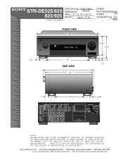
... BUILDING OR APPLICATIONS WHICH REQUIRE A GREAT DEGREE OF PRECISION WE RECOMMEND THAT THE PRODUCT ITSELF BE USED TO MAKE THE ACTUAL MEASUREMENTS. STR-DE525/625 DESCRIPTION: Dolby Digital DIMENSIONS Receiver 825/925 (WHD): 17" x 6 1/4" x 14 1/2" WEIGHT: Approx 27 lbs 1/4 inch = 1 inch Scale 4:1 POWER REQUIREMENTS:120V ...AM. SONY WILL NOT BE RESPONSIBLE FOR INACCURACIES IN THE DESIGN OR MANUFACTURE OF ENCLOSURES . VIDEO VIDEO IN IN VIDEO 2 CTRL-S OUT VIDEO VIDEO OUT IN MD VIDEO 1 CTRL-S OUT VIDEO VIDEO OUT IN MONITOR CTRL-S IN VIDEO OUT S-LINK CD COAXIAL DAT FM COAXIAL ...
... BUILDING OR APPLICATIONS WHICH REQUIRE A GREAT DEGREE OF PRECISION WE RECOMMEND THAT THE PRODUCT ITSELF BE USED TO MAKE THE ACTUAL MEASUREMENTS. STR-DE525/625 DESCRIPTION: Dolby Digital DIMENSIONS Receiver 825/925 (WHD): 17" x 6 1/4" x 14 1/2" WEIGHT: Approx 27 lbs 1/4 inch = 1 inch Scale 4:1 POWER REQUIREMENTS:120V ...AM. SONY WILL NOT BE RESPONSIBLE FOR INACCURACIES IN THE DESIGN OR MANUFACTURE OF ENCLOSURES . VIDEO VIDEO IN IN VIDEO 2 CTRL-S OUT VIDEO VIDEO OUT IN MD VIDEO 1 CTRL-S OUT VIDEO VIDEO OUT IN MONITOR CTRL-S IN VIDEO OUT S-LINK CD COAXIAL DAT FM COAXIAL ...
User Instructions
Page 1
3-864-029-11(1) FM Stereo FM-AM Receiver Operat ing Inst ruct ions STR-DE625 STR-DE525 © 1998 by Sony Corporation
3-864-029-11(1) FM Stereo FM-AM Receiver Operat ing Inst ruct ions STR-DE625 STR-DE525 © 1998 by Sony Corporation
User Instructions
Page 2
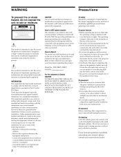
...of electric shock to call upon your nearest Sony dealer. Note to CATV system installer: This reminder is connected. - STR-DE625/DE525 Serial No. On placement • Place the receiver in the literature accompanying the appliance. Do not use the receiver for proper grounding and, in a place ... correct the interference by qualified personnel before operating it is no guarantee that any question or problem concerning your receiver, please consult your Sony dealer regarding this equipment does cause harmful interference to insert the plug fully into an outlet on the rear ...
...of electric shock to call upon your nearest Sony dealer. Note to CATV system installer: This reminder is connected. - STR-DE625/DE525 Serial No. On placement • Place the receiver in the literature accompanying the appliance. Do not use the receiver for proper grounding and, in a place ... correct the interference by qualified personnel before operating it is no guarantee that any question or problem concerning your receiver, please consult your Sony dealer regarding this equipment does cause harmful interference to insert the plug fully into an outlet on the rear ...

User Instructions
Page 3
...have the same or similar names as those on the receiver. Any difference in operation is used in this manual: z Indicates hints and tips for illustration purposes unless stated othewise. In this manual, the USA and Canadian STR-DE625 is clearly indicated in the text, for the r... front speakers Convent ions • The instructions in this manual describe the controls on the receiver. Check your remote, refer to the separate operating instructions supplied ...
...have the same or similar names as those on the receiver. Any difference in operation is used in this manual: z Indicates hints and tips for illustration purposes unless stated othewise. In this manual, the USA and Canadian STR-DE625 is clearly indicated in the text, for the r... front speakers Convent ions • The instructions in this manual describe the controls on the receiver. Check your remote, refer to the separate operating instructions supplied ...
User Instructions
Page 4
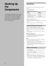
... power to all components before you actually connect them to the receiver. 4 Unpacking Check that you received the following items with the receiver: • FM wire antenna (1) • AM loop antenna (1) • Remote commander (remote) (1) Model Remote STR-DE625 RM-LJ301 STR-DE525 (except Canada) RM-U401 STR-DE525 (Canada) RM-PP401 • R6 (size-AA) batteries (2) •...
... power to all components before you actually connect them to the receiver. 4 Unpacking Check that you received the following items with the receiver: • FM wire antenna (1) • AM loop antenna (1) • Remote commander (remote) (1) Model Remote STR-DE625 RM-LJ301 STR-DE525 (except Canada) RM-U401 STR-DE525 (Canada) RM-PP401 • R6 (size-AA) batteries (2) •...

User Instructions
Page 5
...terminal Notes on antenna hookups • To prevent noise pickup, keep the AM loop antenna away from the receiver and TV. • After connecting the FM wire antenna, keep it against lightning as shown in the illustration in the left column. R L WIRELESS ...REAR SPEAKER IMPEDANCE SELECTOR FRONT 4 Ω 8 Ω FRONT + R - - Note Do not use the SIGNAL GND y terminal for grounding the receiver. 5 Ant enna Hookups AM loop antenna (supplied) FM w ire antenna (supplied) Ho o k i n g Up t h e Co m p o n e n t s ANTENNA AM TV / DBS CTRL S STATUS ...
...terminal Notes on antenna hookups • To prevent noise pickup, keep the AM loop antenna away from the receiver and TV. • After connecting the FM wire antenna, keep it against lightning as shown in the illustration in the left column. R L WIRELESS ...REAR SPEAKER IMPEDANCE SELECTOR FRONT 4 Ω 8 Ω FRONT + R - - Note Do not use the SIGNAL GND y terminal for grounding the receiver. 5 Ant enna Hookups AM loop antenna (supplied) FM w ire antenna (supplied) Ho o k i n g Up t h e Co m p o n e n t s ANTENNA AM TV / DBS CTRL S STATUS ...

User Instructions
Page 6
... CD jacks TAPE/MD jacks Not e on audio com ponent hookups If your turntable has a ground wire, connect it to the appropriate jacks on the receiver. 6 R L WIRELESS REAR SPEAKER IMPEDANCE SELECTOR FRONT 4 Ω 8 Ω FRONT + R - - White (L) White (L) Red (R) Red (R) ANTENNA AM TV / DBS CTRL S STATUS IN VIDEO...S-LINK MONITOR CTRL S IN VIDEO VIDEO VIDEO VIDEO VIDEO VIDEO VIDEO S-LINK IN IN OUT IN OUT IN OUT CTRL A1 y SIGNAL GND COAXIAL FM 75Ω y AUDIO AUDIO AUDIO AUDIO AUDIO IN OUT IN OUT IN L R FRONT REAR CENTER L IN IN RECOUT IN L R WOOFER...
... CD jacks TAPE/MD jacks Not e on audio com ponent hookups If your turntable has a ground wire, connect it to the appropriate jacks on the receiver. 6 R L WIRELESS REAR SPEAKER IMPEDANCE SELECTOR FRONT 4 Ω 8 Ω FRONT + R - - White (L) White (L) Red (R) Red (R) ANTENNA AM TV / DBS CTRL S STATUS IN VIDEO...S-LINK MONITOR CTRL S IN VIDEO VIDEO VIDEO VIDEO VIDEO VIDEO VIDEO S-LINK IN IN OUT IN OUT IN OUT CTRL A1 y SIGNAL GND COAXIAL FM 75Ω y AUDIO AUDIO AUDIO AUDIO AUDIO IN OUT IN OUT IN L R FRONT REAR CENTER L IN IN RECOUT IN L R WOOFER...
User Instructions
Page 7
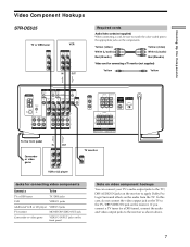
... OUT S-LINK MONITOR CTRL S IN VIDEO VIDEO VIDEO VIDEO VIDEO VIDEO VIDEO S-LINK IN IN OUT IN OUT IN OUT CTRL A1 y SIGNAL GND COAXIAL FM 75Ω y AUDIO AUDIO AUDIO AUDIO AUDIO IN OUT IN OUT IN L R FRONT REAR CENTER L IN IN RECOUT IN L R WOOFER 5.1/DVD INPUT... TV tuner (or a DBS tuner), connect the audio and video output jacks to the TV/DBS VIDEO IN jack on the receiver. Ho o k i n g Up t h e Co m p o n e n t s Video Com ponent Hookups STR-DE625 TV or DBS tuner OUTPUT VIDEO OUT AUDIO OUT L R VCR INPUT OUTPUT VIDEO VIDEO IN OUT AUDIO AUDIO IN OUT L ...
... OUT S-LINK MONITOR CTRL S IN VIDEO VIDEO VIDEO VIDEO VIDEO VIDEO VIDEO S-LINK IN IN OUT IN OUT IN OUT CTRL A1 y SIGNAL GND COAXIAL FM 75Ω y AUDIO AUDIO AUDIO AUDIO AUDIO IN OUT IN OUT IN L R FRONT REAR CENTER L IN IN RECOUT IN L R WOOFER 5.1/DVD INPUT... TV tuner (or a DBS tuner), connect the audio and video output jacks to the TV/DBS VIDEO IN jack on the receiver. Ho o k i n g Up t h e Co m p o n e n t s Video Com ponent Hookups STR-DE625 TV or DBS tuner OUTPUT VIDEO OUT AUDIO OUT L R VCR INPUT OUTPUT VIDEO VIDEO IN OUT AUDIO AUDIO IN OUT L ...
User Instructions
Page 8
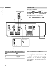
...hookups You can connect your TV's audio output jacks to the TV/ DBS (or TV/LD) AUDIO IN jacks on the receiver to the TV/DBS (or TV/LD) VIDEO IN jack on the audio from the TV. ç Ho o k i... n g Up t h e Co m p o n e n t s Video Com ponent Hookups STR-DE525 VCR INPUT OUTPUT VIDEO VIDEO IN OUT AUDIO AUDIO IN OUT L R * IN OUT Required cords Audio/video cords (not supplied...TV/DBS VIDEO VIDEO IN IN VIDEO MONITOR VIDEO VIDEO VIDEO OUT IN OUT y SIGNAL GND COAXIAL FM 75Ω y AUDIO IN FRONT REAR CENTER IN L AUDIO AUDIO OUT IN L R IN RECOUT...
...hookups You can connect your TV's audio output jacks to the TV/ DBS (or TV/LD) AUDIO IN jacks on the receiver to the TV/DBS (or TV/LD) VIDEO IN jack on the audio from the TV. ç Ho o k i... n g Up t h e Co m p o n e n t s Video Com ponent Hookups STR-DE525 VCR INPUT OUTPUT VIDEO VIDEO IN OUT AUDIO AUDIO IN OUT L R * IN OUT Required cords Audio/video cords (not supplied...TV/DBS VIDEO VIDEO IN IN VIDEO MONITOR VIDEO VIDEO VIDEO OUT IN OUT y SIGNAL GND COAXIAL FM 75Ω y AUDIO IN FRONT REAR CENTER IN L AUDIO AUDIO OUT IN L R IN RECOUT...

User Instructions
Page 9
...DVD INPUT CENTER and WOOFER jacks Black Black Video cord (not supplied) One for details on speaker system hookup. 9 TUNING + SLEEP FM MODE FM/AM MEMORY SHIFT 6 7 8 9 9 5.1/ DVD INPUT VIDEO IN SPEAKERS FRONT VIDEO 1 FUNCTION VIDEO 2 VIDEO 3 TV/DBS TAPE.../ TREBLE INDEX g SPEAKERS OFF A B A+B DISPLAY DIRECT TUNING 1 2 3 4 5 PHONES - Ho o k i n g Up t h e Co m p o n e n t s 5.1 Input Hookups This receiver is equipped with your own home. TUNING + PRESET - To enjoy Multi-Channel Surround sound to these jacks, you will need five speakers (two front speakers...
...DVD INPUT CENTER and WOOFER jacks Black Black Video cord (not supplied) One for details on speaker system hookup. 9 TUNING + SLEEP FM MODE FM/AM MEMORY SHIFT 6 7 8 9 9 5.1/ DVD INPUT VIDEO IN SPEAKERS FRONT VIDEO 1 FUNCTION VIDEO 2 VIDEO 3 TV/DBS TAPE.../ TREBLE INDEX g SPEAKERS OFF A B A+B DISPLAY DIRECT TUNING 1 2 3 4 5 PHONES - Ho o k i n g Up t h e Co m p o n e n t s 5.1 Input Hookups This receiver is equipped with your own home. TUNING + PRESET - To enjoy Multi-Channel Surround sound to these jacks, you will need five speakers (two front speakers...
User Instructions
Page 10
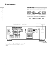
...receiver is shipped. b To a w all outlet 10 Ho o k i n g Up t h e Co m p o n e n t s Ot her Hookups Required cords Audio/video/control S connecting cord (1) (supplied with STRDE625 only) Yellow (video) White (L/ audio) Red (R/ audio) Black (control S) Yellow (video) White (L/ audio) Red (R/ audio) Black (control S) Control S connecting cord (1) (supplied with STR-DE625... VIDEO VIDEO VIDEO VIDEO VIDEO VIDEO VIDEO S-LINK IN IN OUT IN OUT IN OUT CTRL A1 y SIGNAL GND COAXIAL FM 75Ω y AUDIO AUDIO AUDIO AUDIO AUDIO IN OUT IN OUT IN L R FRONT REAR CENTER L IN IN ...
...receiver is shipped. b To a w all outlet 10 Ho o k i n g Up t h e Co m p o n e n t s Ot her Hookups Required cords Audio/video/control S connecting cord (1) (supplied with STRDE625 only) Yellow (video) White (L/ audio) Red (R/ audio) Black (control S) Yellow (video) White (L/ audio) Red (R/ audio) Black (control S) Control S connecting cord (1) (supplied with STR-DE625... VIDEO VIDEO VIDEO VIDEO VIDEO VIDEO VIDEO S-LINK IN IN OUT IN OUT IN OUT CTRL A1 y SIGNAL GND COAXIAL FM 75Ω y AUDIO AUDIO AUDIO AUDIO AUDIO IN OUT IN OUT IN L R FRONT REAR CENTER L IN IN ...
User Instructions
Page 11
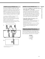
...VCR etc.) jack on the receiver to the appropriate S-LINK jack on the receiver. See "Displaying the operating status of the receiver is shown below. VOLTAGE SELECT 220V 240V 120V 11 Ho o k i n g Up t h e Co m p o n e n t s CONTROL S hookup (STR-DE625 only) If you have a CONTROL S-compatible Sony TV, DBS tuner, monitor... cord ** Control S connecting cord CONTROL A1 hookup (STR-DE625 only) • If you turn on the VCR. When you connect the VCR to the receiver as shown below , the input mode of a CONTROL S hookup between the receiver and TV or VCR is set to the local power...
...VCR etc.) jack on the receiver to the appropriate S-LINK jack on the receiver. See "Displaying the operating status of the receiver is shown below. VOLTAGE SELECT 220V 240V 120V 11 Ho o k i n g Up t h e Co m p o n e n t s CONTROL S hookup (STR-DE625 only) If you have a CONTROL S-compatible Sony TV, DBS tuner, monitor... cord ** Control S connecting cord CONTROL A1 hookup (STR-DE625 only) • If you turn on the VCR. When you connect the VCR to the receiver as shown below , the input mode of a CONTROL S hookup between the receiver and TV or VCR is set to the local power...

User Instructions
Page 12
.... 12 Do not connect high-wattage electrical home appliances such as electric irons, fans, or TVs to this receiver to a wall outlet: • Connect the speaker system to the receiver (see page 14). • Turn the MASTER VOLUME control to the leftmost position (0). If you connect other... audio/video components to AC OUTLET on the receiver, the receiver will supply power to the connected component(s), allowing you to a wall outlet. Connect the AC power cord(s) of your audio/video component(s)...
.... 12 Do not connect high-wattage electrical home appliances such as electric irons, fans, or TVs to this receiver to a wall outlet: • Connect the speaker system to the receiver (see page 14). • Turn the MASTER VOLUME control to the leftmost position (0). If you connect other... audio/video components to AC OUTLET on the receiver, the receiver will supply power to the connected component(s), allowing you to a wall outlet. Connect the AC power cord(s) of your audio/video component(s)...

User Instructions
Page 13
BALANCE control: Used to select "PRO LOGIC" when adjusting the speaker volume. TUNING + SLEEP FM MODE FM/AM MEMORY SHIFT 6 7 8 9 9 VIDEO 1 FUNCTION VIDEO 2 VIDEO 3 TV/DBS TAPE/MD CD TUNER PHONO 5.1/DVD INPUT TONE BASS BOOST SOUND FIELD GENRE MODE 5.1/DVD BASS ... up t he Speaker Syst em Hooking Up and Setting Up the Speaker System This chapter describes how to hook up your speaker system to the receiver, how to position each speaker, and how to set up your speakers to enjoy Dolby Surround sound. M ODE button: Used to adjust the front speaker...
BALANCE control: Used to select "PRO LOGIC" when adjusting the speaker volume. TUNING + SLEEP FM MODE FM/AM MEMORY SHIFT 6 7 8 9 9 VIDEO 1 FUNCTION VIDEO 2 VIDEO 3 TV/DBS TAPE/MD CD TUNER PHONO 5.1/DVD INPUT TONE BASS BOOST SOUND FIELD GENRE MODE 5.1/DVD BASS ... up t he Speaker Syst em Hooking Up and Setting Up the Speaker System This chapter describes how to hook up your speaker system to the receiver, how to position each speaker, and how to set up your speakers to enjoy Dolby Surround sound. M ODE button: Used to adjust the front speaker...

User Instructions
Page 16
... for sound fields other than PRO LOGIC. Each mode is output from each center mode is fully reproduced Adjust ing t he cent er m ode The receiver offers you four center modes: PHANTOM, 3CH LOGIC, NORMAL, and WIDE. You will hear a test tone (see the table on this page) from each speaker... speakers, but no center speaker The sound of the center channel is output from the front speakers Front and center 3CH LOGIC speakers, but no (3-STEREO) rear speaker The sound of the rear channel is output from the front speakers Front and rear speakers, and a small center speaker NORMAL The bass...
... for sound fields other than PRO LOGIC. Each mode is output from each center mode is fully reproduced Adjust ing t he cent er m ode The receiver offers you four center modes: PHANTOM, 3CH LOGIC, NORMAL, and WIDE. You will hear a test tone (see the table on this page) from each speaker... speakers, but no center speaker The sound of the center channel is output from the front speakers Front and center 3CH LOGIC speakers, but no (3-STEREO) rear speaker The sound of the rear channel is output from the front speakers Front and rear speakers, and a small center speaker NORMAL The bass...
User Instructions
Page 17
.../ TREBLE INDEX g SPEAKERS OFF A B A+B DISPLAY DIRECT TUNING 1 2 3 4 5 PHONES - DE625) or VIDEO and TAPE/ M D (STR-DE525), press 1/u to their factory settings. • The sound field memorized for front speakers that are not connected to the receiver (see "8 SPEAKERS selector" on the receiver. TUNING + PRESET - TUNING + SLEEP FM MODE FM/AM MEMORY SHIFT 6 7 8 9 9 VIDEO 1 FUNCTION VIDEO 2 VIDEO 3 TV...
.../ TREBLE INDEX g SPEAKERS OFF A B A+B DISPLAY DIRECT TUNING 1 2 3 4 5 PHONES - DE625) or VIDEO and TAPE/ M D (STR-DE525), press 1/u to their factory settings. • The sound field memorized for front speakers that are not connected to the receiver (see "8 SPEAKERS selector" on the receiver. TUNING + PRESET - TUNING + SLEEP FM MODE FM/AM MEMORY SHIFT 6 7 8 9 9 VIDEO 1 FUNCTION VIDEO 2 VIDEO 3 TV...

User Instructions
Page 18
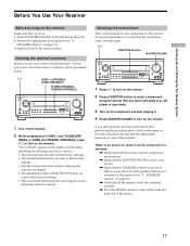
...control is set at center position (see "6 BALANCE control" on page 21). / Connect a pair of t he Speaker Syst em Bef ore You Use Your Receiver There's no sound f rom a specif ic com ponent . / Check that the component is connected correctly to the audio input jacks for that component. / Check...output from the headphones, the front speaker may not be connected to verify that sound output is from the conncted headphones, the component and the receiver may not be connected correctly. If you encounter a problem that the cord(s) used for the front speaker from which no sound is output. /...
...control is set at center position (see "6 BALANCE control" on page 21). / Connect a pair of t he Speaker Syst em Bef ore You Use Your Receiver There's no sound f rom a specif ic com ponent . / Check that the component is connected correctly to the audio input jacks for that component. / Check...output from the headphones, the front speaker may not be connected to verify that sound output is from the conncted headphones, the component and the receiver may not be connected correctly. If you encounter a problem that the cord(s) used for the front speaker from which no sound is output. /...

User Instructions
Page 20
... you selected. • Press the 5.1/DVD INPUT button to select the component connected to turn the receiver on and off. To select Press VCR VIDEO 1 or VIDEO 2 (STRDE625) VIDEO (STR-DE525) Camcorder or video game VIDEO 3 (STR-DE625 only) TV, DBS tuner*, or LD player TV/DBS (USA, Canada, and Australia) TV/LD (all... the TV and set the TV's video input to match the component you selected and play the program source. Note Before you turn on the receiver, make sure that you have selected VCR, camcorder, video game, or LD player, turn on page 21).
... you selected. • Press the 5.1/DVD INPUT button to select the component connected to turn the receiver on and off. To select Press VCR VIDEO 1 or VIDEO 2 (STRDE625) VIDEO (STR-DE525) Camcorder or video game VIDEO 3 (STR-DE625 only) TV, DBS tuner*, or LD player TV/DBS (USA, Canada, and Australia) TV/LD (all... the TV and set the TV's video input to match the component you selected and play the program source. Note Before you turn on the receiver, make sure that you have selected VCR, camcorder, video game, or LD player, turn on page 21).

User Instructions
Page 21
...connection) B A+B* No front speaker output OFF * Do not set the SPEAKERS selector to OFF to output sound to mute the sound. TUNING + SLEEP FM MODE FM/AM MEMORY SHIFT 6 7 8 9 9 VIDEO 1 FUNCTION VIDEO 2 VIDEO 3 TV/DBS TAPE/MD CD TUNER PHONO 5.1/DVD INPUT TONE BASS BOOST ...L R VIDEO 3 INPUT VIDEO L AUDIO R 87 Locat ion of the front speakers. 7 SLEEP button Press to select the time after which the receiver turns off automatically (see page 35). 8 SPEAKERS selector Set according to the front speakers you selected, rotate to adjust the volume. 5 M UTING button...
...connection) B A+B* No front speaker output OFF * Do not set the SPEAKERS selector to OFF to output sound to mute the sound. TUNING + SLEEP FM MODE FM/AM MEMORY SHIFT 6 7 8 9 9 VIDEO 1 FUNCTION VIDEO 2 VIDEO 3 TV/DBS TAPE/MD CD TUNER PHONO 5.1/DVD INPUT TONE BASS BOOST ...L R VIDEO 3 INPUT VIDEO L AUDIO R 87 Locat ion of the front speakers. 7 SLEEP button Press to select the time after which the receiver turns off automatically (see page 35). 8 SPEAKERS selector Set according to the front speakers you selected, rotate to adjust the volume. 5 M UTING button...

User Instructions
Page 22
.... Numeric buttons (1 to select "CINEMA" or "MUSIC" sound field group. TUNING + SLEEP FM MODE FM/AM MEMORY SHIFT 6 7 8 9 9 VIDEO 1 FUNCTION VIDEO 2 VIDEO 3 TV/DBS TAPE...TREBLE INDEX g SPEAKERS OFF A B A+B DISPLAY DIRECT TUNING 1 2 3 4 5 PHONES - For details, see "Receiving Broadcasts" starting from the front speakers that if you have adjusted the tone using the CURSOR MODE button and cursor buttons,... buttons operate the built-in tuner. The result will be a two-channel stereo sound output from page 24. DIRECT TUNING button Enables Direct Tuning (see page...
.... Numeric buttons (1 to select "CINEMA" or "MUSIC" sound field group. TUNING + SLEEP FM MODE FM/AM MEMORY SHIFT 6 7 8 9 9 VIDEO 1 FUNCTION VIDEO 2 VIDEO 3 TV/DBS TAPE...TREBLE INDEX g SPEAKERS OFF A B A+B DISPLAY DIRECT TUNING 1 2 3 4 5 PHONES - For details, see "Receiving Broadcasts" starting from the front speakers that if you have adjusted the tone using the CURSOR MODE button and cursor buttons,... buttons operate the built-in tuner. The result will be a two-channel stereo sound output from page 24. DIRECT TUNING button Enables Direct Tuning (see page...


