
Operating Instructions
Page 12
Presetting radio stations Presetting radio stations 1 2 3 4 5 Tuning to preset stations 1 2 tA1yA2y...yA0yB1yB2y...yB0T tC0y...yC2yC1T Using the remote 1 2 To select the preset station directly 6 Note 12GB
Presetting radio stations Presetting radio stations 1 2 3 4 5 Tuning to preset stations 1 2 tA1yA2y...yA0yB1yB2y...yB0T tC0y...yC2yC1T Using the remote 1 2 To select the preset station directly 6 Note 12GB
Operating Instructions
Page 15
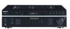
Changing the display Changing the information in the display Adjusting the sound Adjusting the speaker balance t When the tuner is selected t t t t y y y y Adjusting the tone Reinforcing the bass 15GB
Changing the display Changing the information in the display Adjusting the sound Adjusting the speaker balance t When the tuner is selected t t t t y y y y Adjusting the tone Reinforcing the bass 15GB

Service Manual
Page 1
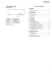
..., input le vel. FM STEREO/FM-AM RECEIVER 9-877-864-06 2007E04-1 © 2007. 05 Sony Corporation Home Audio Division Published by Sony Techno Create Corporation 1 Amplifier section POWER OUTPUT Models of area code US, CND Power Output a t Ster eo Mode (8 ohms 1 kHz, THD 0.7 %) 125 W + 125 W 1) Models of area code US only) With 8 ohm loads, both channels driven, from 250 milliwatts to rated output. SERVICE MANUAL Ver. 1.5 2007. 05 STR-DE197 US Model Canadian Model...
..., input le vel. FM STEREO/FM-AM RECEIVER 9-877-864-06 2007E04-1 © 2007. 05 Sony Corporation Home Audio Division Published by Sony Techno Create Corporation 1 Amplifier section POWER OUTPUT Models of area code US, CND Power Output a t Ster eo Mode (8 ohms 1 kHz, THD 0.7 %) 125 W + 125 W 1) Models of area code US only) With 8 ohm loads, both channels driven, from 250 milliwatts to rated output. SERVICE MANUAL Ver. 1.5 2007. 05 STR-DE197 US Model Canadian Model...

Service Manual
Page 2
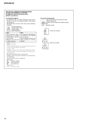
... LINE WITH MARK 0 ON THE SCHEMATIC DIAGRAMS AND IN THE PARTS LIST ARE CRITICAL TO SAFE OPERATION. A battery-operated AC milliammeter. STR-DE197 AM tuner section Tuning range Models of area code US, CND With 10-kHz tuning scale: 530 - 1,710 kHz 4) With 9-kHz tuning scale: 531 - 1,710 kHz 4) Models of area code AEP With 9-kHz tuning scale: 531 - 1,602 kHz Antenna Intermediate frequency Usable sensitivity S/N Harmonic distortion...
... LINE WITH MARK 0 ON THE SCHEMATIC DIAGRAMS AND IN THE PARTS LIST ARE CRITICAL TO SAFE OPERATION. A battery-operated AC milliammeter. STR-DE197 AM tuner section Tuning range Models of area code US, CND With 10-kHz tuning scale: 530 - 1,710 kHz 4) With 9-kHz tuning scale: 531 - 1,710 kHz 4) Models of area code AEP With 9-kHz tuning scale: 531 - 1,602 kHz Antenna Intermediate frequency Usable sensitivity S/N Harmonic distortion...
Service Manual
Page 3
...2-1. TEST MODE 10 4. DIAGRAMS 4-1. Circuit Boards Location 13 4-3. Power Section 16 4-5. Main Section (1/2 18 4-7. Printed Wiring Boards - Panel Section 21 4-10. Block Diagram - Block Diagram - Panel Section 20 4-9. Chassis Section 25 6. ELECTRICAL PARTS LIST 26 3 IC Block Diagrams 22 5. Front Panel Section 8 2-3. Main Section 17 4-6. Schematic Diagram - EXPLODED VIEWS 5-1. Case 7 2-2. Back Panel 8 2-4. IC Pin Description 11 4-2. Case Section 23 5-2. Schematic Diagram - BACK PANEL - MODEL IDENTIFICATION - GENERAL Main unit 4 Remote button...
...2-1. TEST MODE 10 4. DIAGRAMS 4-1. Circuit Boards Location 13 4-3. Power Section 16 4-5. Main Section (1/2 18 4-7. Printed Wiring Boards - Panel Section 21 4-10. Block Diagram - Block Diagram - Panel Section 20 4-9. Chassis Section 25 6. ELECTRICAL PARTS LIST 26 3 IC Block Diagrams 22 5. Front Panel Section 8 2-3. Main Section 17 4-6. Schematic Diagram - EXPLODED VIEWS 5-1. Case 7 2-2. Back Panel 8 2-4. IC Pin Description 11 4-2. Case Section 23 5-2. Schematic Diagram - BACK PANEL - MODEL IDENTIFICATION - GENERAL Main unit 4 Remote button...

Service Manual
Page 10
... +] button, press the ?/1 button to turn on one after another. Software Version Display Mode The software version is activated, all light off 3. STR-DE197 SECTION 3 TEST MODE Fluorescent Indicator Tube Test Mode All fluorescent segments are scrolled for a moment and the receiver starts scanning. Procedure: 1. The FL tube will be selected for a moment and select the desired step. AUTO-BETICAL Check Mode (AEP model) To auto-scanning and memories of function buttons all light...
... +] button, press the ?/1 button to turn on one after another. Software Version Display Mode The software version is activated, all light off 3. STR-DE197 SECTION 3 TEST MODE Fluorescent Indicator Tube Test Mode All fluorescent segments are scrolled for a moment and the receiver starts scanning. Procedure: 1. The FL tube will be selected for a moment and select the desired step. AUTO-BETICAL Check Mode (AEP model) To auto-scanning and memories of function buttons all light...

Service Manual
Page 11
... O Digit drive signal output to AD1 I Destination select signal input (Fixed at L in this set ) 32 OPEN - IC PIN DESCRIPTION • IC201 µPD78045FGF-134-3B9 (SYSTEM CONTROLLER, FL DISPLAY DRIVER) Pin No. LED O BASS BOOST LED drive signal output 54 SPK A LED O SPEAKER A LED drive signal output 55 SPK B LED O SPEAKER B LED drive signal output 11 Not used . (Open) 33 GND - Pin Name I Sircs signal input from FM/AM tuner pack. 20 AVSS - A/D converter power supply...
... O Digit drive signal output to AD1 I Destination select signal input (Fixed at L in this set ) 32 OPEN - IC PIN DESCRIPTION • IC201 µPD78045FGF-134-3B9 (SYSTEM CONTROLLER, FL DISPLAY DRIVER) Pin No. LED O BASS BOOST LED drive signal output 54 SPK A LED O SPEAKER A LED drive signal output 55 SPK B LED O SPEAKER B LED drive signal output 11 Not used . (Open) 33 GND - Pin Name I Sircs signal input from FM/AM tuner pack. 20 AVSS - A/D converter power supply...
Service Manual
Page 14
... 1/4 W or less unless otherwise specified. • f : internal component. • 2 : nonflammable resistor. • 1 : fusible resistor. • C : panel designation. C Q These are omitted. 14 Note: Les composants identifiés par une marque 0 sont critiques pour la sécurité. STR-DE197 THIS NOTE IS COMMON FOR PRINTED WIRING BOARDS AND SCHEMATIC DIAGRAMS. (In addition to this, the necessary note is...
... 1/4 W or less unless otherwise specified. • f : internal component. • 2 : nonflammable resistor. • 1 : fusible resistor. • C : panel designation. C Q These are omitted. 14 Note: Les composants identifiés par une marque 0 sont critiques pour la sécurité. STR-DE197 THIS NOTE IS COMMON FOR PRINTED WIRING BOARDS AND SCHEMATIC DIAGRAMS. (In addition to this, the necessary note is...

Service Manual
Page 15
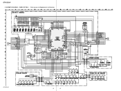
... (1/2) VIDEO 2 -1 L AUDIO IN-2 R R-CH R-CH VIDEO 1 -5 L AUDIO IN -6 R R-CH TUNER 9L SOUND CONTROL IC401 REC L 32 CD L 7 VOL L 29 MD L 5 VIDEO 2 3 TREBLE L MIDDLE L BASS L OUT L 20 VIDEO 1 1 CONTROL 15 14 CLK DATA CLK DATA STB STR-DE197 AUDIO AMP IC403 3 1 ELECTRONIC VOLUME IC402 L 3 IN L OUT 2 VOLUME CONTROL 8 9 10 VIDEO 1,MD/TAPE SELECT IC404 1 2 4 3 13 5 Q474 INV. J801 (2/2) -3 L R-CH -4 R OUT MD/TAPE J802 (2/2) -3 L R-CH -4 R AUDIO OUT VIDEO 1 R-CH ST-L ST-R A POWER SECTION (Page 16) STEREO TUNED...
... (1/2) VIDEO 2 -1 L AUDIO IN-2 R R-CH R-CH VIDEO 1 -5 L AUDIO IN -6 R R-CH TUNER 9L SOUND CONTROL IC401 REC L 32 CD L 7 VOL L 29 MD L 5 VIDEO 2 3 TREBLE L MIDDLE L BASS L OUT L 20 VIDEO 1 1 CONTROL 15 14 CLK DATA CLK DATA STB STR-DE197 AUDIO AMP IC403 3 1 ELECTRONIC VOLUME IC402 L 3 IN L OUT 2 VOLUME CONTROL 8 9 10 VIDEO 1,MD/TAPE SELECT IC404 1 2 4 3 13 5 Q474 INV. J801 (2/2) -3 L R-CH -4 R OUT MD/TAPE J802 (2/2) -3 L R-CH -4 R AUDIO OUT VIDEO 1 R-CH ST-L ST-R A POWER SECTION (Page 16) STEREO TUNED...

Service Manual
Page 18
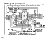
STR-DE197 4-6. SCHEMATIC DIAGRAM - MAIN SECTION (1/2) - • Refer to page 14 for Common Note on Schematic Diagram and page 22 for IC Block Diagrams. J801 J802 TN1 CC451 R451 CC401 R401 R452 R402 C452 C402 CC453 CC403 R453 R403 R454 R404 C454 C404 CC455 CC405 R455 R405 R456 R406 ... Q474 R421 R424 Q424 R422 C425 R423 R485 R471 D914 R472 C928 IC903 R473 C475 C925 C924 R918 R919 R920 R425 R475 JW900 CNS2 C931 LEVEL SHIFT IC906 C942 R946 R947 Q905 Q906 JW901 R484 R483 IC B/D IC601 R697 C608 C603 C654 C604 C653 C658 R930 R602 C602 R652 C652 C657...
STR-DE197 4-6. SCHEMATIC DIAGRAM - MAIN SECTION (1/2) - • Refer to page 14 for Common Note on Schematic Diagram and page 22 for IC Block Diagrams. J801 J802 TN1 CC451 R451 CC401 R401 R452 R402 C452 C402 CC453 CC403 R453 R403 R454 R404 C454 C404 CC455 CC405 R455 R405 R456 R406 ... Q474 R421 R424 Q424 R422 C425 R423 R485 R471 D914 R472 C928 IC903 R473 C475 C925 C924 R918 R919 R920 R425 R475 JW900 CNS2 C931 LEVEL SHIFT IC906 C942 R946 R947 Q905 Q906 JW901 R484 R483 IC B/D IC601 R697 C608 C603 C654 C604 C653 C658 R930 R602 C602 R652 C652 C657...

Service Manual
Page 21
SCHEMATIC DIAGRAM - STR-DE197 C217 R227 C218 R228 (Page 18) STR-DE197 IC202 CNS4 D204 FL201 C225 R237 R293 R242 C205 R294 C202 C203 C204 R238 R241 Q201 Q202 C219 R231 R232 R233 R234 R235 R236 R244 ... R261 R256 R257 R258 R259 R260 S232 S233 S234 S235 S236 • Waveform 1 2V/div 0.2µsec/div 3.6Vp-p 4.19MHz IC201 eg (X2) 21 21 PANEL SECTION - • Refer to page 14 for Common Note on Schematic Diagram. 4-9.
SCHEMATIC DIAGRAM - STR-DE197 C217 R227 C218 R228 (Page 18) STR-DE197 IC202 CNS4 D204 FL201 C225 R237 R293 R242 C205 R294 C202 C203 C204 R238 R241 Q201 Q202 C219 R231 R232 R233 R234 R235 R236 R244 ... R261 R256 R257 R258 R259 R260 S232 S233 S234 S235 S236 • Waveform 1 2V/div 0.2µsec/div 3.6Vp-p 4.19MHz IC201 eg (X2) 21 21 PANEL SECTION - • Refer to page 14 for Common Note on Schematic Diagram. 4-9.

Service Manual
Page 23
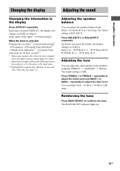
Replace only with part number specified. No. 3 4 5 #1 Part No. SECTION 5 EXPLODED VIEWS • Color Indication of this parts list. • Abbreviation CND : Canadian model 5-1. No. 1 1 1 2 2 Part No. CASE SECTION 2 STR-DE197 Ver. 1.2 The components identified by mark 0 or dotted line with mark 0 are given in the exploded views...8226; The mechanical parts with no reference number in the last of Appearance Parts Example : KNOB, BALANCE (WHITE) ... (RED) R R Parts Color Cabinet's Color • Accessories are critical for safety. Some delay should be anticipated ...
Replace only with part number specified. No. 3 4 5 #1 Part No. SECTION 5 EXPLODED VIEWS • Color Indication of this parts list. • Abbreviation CND : Canadian model 5-1. No. 1 1 1 2 2 Part No. CASE SECTION 2 STR-DE197 Ver. 1.2 The components identified by mark 0 or dotted line with mark 0 are given in the exploded views...8226; The mechanical parts with no reference number in the last of Appearance Parts Example : KNOB, BALANCE (WHITE) ... (RED) R R Parts Color Cabinet's Color • Accessories are critical for safety. Some delay should be anticipated ...
Service Manual
Page 26
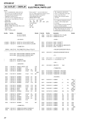
...uPC.. : µPC.. No. Some delay should be different from the original one. • RESISTORS All resistors are in the diagrams or the components used on the set. • -XX and -X mean standardized parts, so they are seldom required for safety. When indicating parts by mark 0 or dotted line with part number..... Replace only with mark 0 are critical for routine service. Ne les remplacer que par une piéce portant le numéro spécifié. STR-DE197 SECTION 6 AC OUTLET DISPLAY ELECTRICAL PARTS LIST NOTE: • Due to standardization, replacements in the parts list...
...uPC.. : µPC.. No. Some delay should be different from the original one. • RESISTORS All resistors are in the diagrams or the components used on the set. • -XX and -X mean standardized parts, so they are seldom required for safety. When indicating parts by mark 0 or dotted line with part number..... Replace only with mark 0 are critical for routine service. Ne les remplacer que par une piéce portant le numéro spécifié. STR-DE197 SECTION 6 AC OUTLET DISPLAY ELECTRICAL PARTS LIST NOTE: • Due to standardization, replacements in the parts list...

Service Manual
Page 33
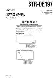
STR-DE197 SERVICE MANUAL Ver. 1.3 2006. 09 US Model Canadian Model AEP Model SUPPLEMENT-1 File this Supplement-1. Subject: Change the MAIN, DISPLAY, VOLUME, H.PHONE, POWER, FUNCTION KEY and AC OUTLET boards. When performing service and inspection, check the part number of new type, and changed parts list are described in this supplement with the service manual. DISCRIMINATION - Printed wiring board and schematic diagram of the MAIN, DISPLAY, VOLUME, H.PHONE, POWER, FUNCTION KEY and AC OUTLET boards. DISPLAY BOARD...
STR-DE197 SERVICE MANUAL Ver. 1.3 2006. 09 US Model Canadian Model AEP Model SUPPLEMENT-1 File this Supplement-1. Subject: Change the MAIN, DISPLAY, VOLUME, H.PHONE, POWER, FUNCTION KEY and AC OUTLET boards. When performing service and inspection, check the part number of new type, and changed parts list are described in this supplement with the service manual. DISCRIMINATION - Printed wiring board and schematic diagram of the MAIN, DISPLAY, VOLUME, H.PHONE, POWER, FUNCTION KEY and AC OUTLET boards. DISPLAY BOARD...

Service Manual
Page 35
... 17 16 15 MODE SELECTOR MCU I/F REF SURROUND TONE CONTROL L-CH BASS/TREBLE INPUT SELECTOR MUTE INPUT GAIN CONTROL INPUT GAIN CONTROL TONE CONTROL R-CH BASS/TREBLE VOLUME VOLUME 1 2 3 4 5 6 7 8 9 10 11 12 13 14 INR3 INR2 INR1 INL1 INL2 INL3 INL4 IGOUTL VOLINL IGOUTR VOLINR BASSR1 BASSR2 BASSL1 • Waveform 1 IC201 eg (X2) 4.19 MHz 2V/DIV, 0.2µsec/DIV 3.6 Vp-p STR-DE197 3 3 Schematic Diagram -Main Section (1/2 5 3. Schematic Diagram -Panel Section 8 6. Voltage...
... 17 16 15 MODE SELECTOR MCU I/F REF SURROUND TONE CONTROL L-CH BASS/TREBLE INPUT SELECTOR MUTE INPUT GAIN CONTROL INPUT GAIN CONTROL TONE CONTROL R-CH BASS/TREBLE VOLUME VOLUME 1 2 3 4 5 6 7 8 9 10 11 12 13 14 INR3 INR2 INR1 INL1 INL2 INL3 INL4 IGOUTL VOLINL IGOUTR VOLINR BASSR1 BASSR2 BASSL1 • Waveform 1 IC201 eg (X2) 4.19 MHz 2V/DIV, 0.2µsec/DIV 3.6 Vp-p STR-DE197 3 3 Schematic Diagram -Main Section (1/2 5 3. Schematic Diagram -Panel Section 8 6. Voltage...
Service Manual
Page 40
... R287 S204 S205 S206 S207 S208 S209 S210 S211 R262 S239 S238 CN200 CNP200 R261 R256 R257 R258 R259 R260 S232 S233 S234 S235 S236 STR-DE197 8 8 PANEL SECTION - • Refer to page 3 of Supplement-1 for Waveform. STR-DE197 5. SCHEMATIC DIAGRAM -
... R287 S204 S205 S206 S207 S208 S209 S210 S211 R262 S239 S238 CN200 CNP200 R261 R256 R257 R258 R259 R260 S232 S233 S234 S235 S236 STR-DE197 8 8 PANEL SECTION - • Refer to page 3 of Supplement-1 for Waveform. STR-DE197 5. SCHEMATIC DIAGRAM -
Service Manual
Page 49
... the service manual. MAIN BOARD Part No. 1-861-592-1 : Service Manual 1-871-790-1 :Supplement-1 1-861-592-2 :Supplement-2 - DISPLAY BOARD (COMPONENT SIDE) - DISPLAY BOARD Part No. 1-861-586-1 : Service Manual 1-871-791-1 :Supplement-1 1-861-586-2 :Supplement-2 9-877-864-82 1 STR-DE197 SERVICE MANUAL Ver. 1.4 2007. 03 US Model Canadian Model AEP Model SUPPLEMENT-2 File this Supplement-2. Printed wiring board and schematic diagram of US model. DISCRIMINATION - When performing service and inspection, check the part number of...
... the service manual. MAIN BOARD Part No. 1-861-592-1 : Service Manual 1-871-790-1 :Supplement-1 1-861-592-2 :Supplement-2 - DISPLAY BOARD (COMPONENT SIDE) - DISPLAY BOARD Part No. 1-861-586-1 : Service Manual 1-871-791-1 :Supplement-1 1-861-586-2 :Supplement-2 9-877-864-82 1 STR-DE197 SERVICE MANUAL Ver. 1.4 2007. 03 US Model Canadian Model AEP Model SUPPLEMENT-2 File this Supplement-2. Printed wiring board and schematic diagram of US model. DISCRIMINATION - When performing service and inspection, check the part number of...
Service Manual
Page 50
Schematic Diagram -Main Section (2/2 6 4. Printed Wiring Boards -Main Section 4 2. Printed Wiring Boards -Panel Section 7 5. Schematic Diagram -Main Section (1/2 5 3. STR-DE197 TABLE OF CONTENTS 1. Electrical Parts List 9 2 Schematic Diagram -Panel Section 8 6.
Schematic Diagram -Main Section (2/2 6 4. Printed Wiring Boards -Main Section 4 2. Printed Wiring Boards -Panel Section 7 5. Schematic Diagram -Main Section (1/2 5 3. STR-DE197 TABLE OF CONTENTS 1. Electrical Parts List 9 2 Schematic Diagram -Panel Section 8 6.

Service Manual
Page 51
...;curité. STR-DE197 • IC Block Diagram IC402 R2S15904SP INR4 LOUT ROUT AGND VCC REFIN DATA CLK DGND TRER TREL NC NC BASSL2 28 27 26 INPUT SELECTOR MUTE 25 24 23 22 21 20 19 18 17 16 15 MODE SELECTOR MCU I/F REF SURROUND TONE CONTROL L-CH BASS/TREBLE INPUT SELECTOR MUTE INPUT GAIN CONTROL INPUT GAIN CONTROL TONE CONTROL R-CH BASS/TREBLE VOLUME VOLUME 1 2 3 4 5 6 7 8 9 10 11...
...;curité. STR-DE197 • IC Block Diagram IC402 R2S15904SP INR4 LOUT ROUT AGND VCC REFIN DATA CLK DGND TRER TREL NC NC BASSL2 28 27 26 INPUT SELECTOR MUTE 25 24 23 22 21 20 19 18 17 16 15 MODE SELECTOR MCU I/F REF SURROUND TONE CONTROL L-CH BASS/TREBLE INPUT SELECTOR MUTE INPUT GAIN CONTROL INPUT GAIN CONTROL TONE CONTROL R-CH BASS/TREBLE VOLUME VOLUME 1 2 3 4 5 6 7 8 9 10 11...
Service Manual
Page 56
SCHEMATIC DIAGRAM - PANEL SECTION - • Refer to page 3 of Supplement-2 for Waveform. STR-DE197 5. R227 C217 C218 R228 R202 R203 R204 R205 R206 R207 R208 R209 R210 R211 R212 R213 R214 R215 R216 R217 R218 R219 R220 R221 R222 R223 R224 R225 R226 ((Page 5)) STR-DE197 IC202 CNS4 D204 FL201 C225 R293 Q201 R294 C202 C203 C204 R238...
SCHEMATIC DIAGRAM - PANEL SECTION - • Refer to page 3 of Supplement-2 for Waveform. STR-DE197 5. R227 C217 C218 R228 R202 R203 R204 R205 R206 R207 R208 R209 R210 R211 R212 R213 R214 R215 R216 R217 R218 R219 R220 R221 R222 R223 R224 R225 R226 ((Page 5)) STR-DE197 IC202 CNS4 D204 FL201 C225 R293 Q201 R294 C202 C203 C204 R238...


