Sony STR DE197 Support Question
Sony STR DE197 Support Question
Find answers below for this question about Sony STR DE197 - AV Receiver.Need a Sony STR DE197 manual? We have 2 online manuals for this item!
Question posted by jerrykloecker on October 11th, 2016
Sony Str-de197 Will Not Turn On.
My Sony STR-DE197 was plugged into a power strip, but not operating, during a thunderstorm with lightning. Now it will not turn on. The fuse is fine. Any ideas on any other reason for lack of power (e.g., possibly a thermal fuse)? Thank you for any help.
Current Answers
Answer #1: Posted by waelsaidani1 on October 26th, 2016 2:53 AM
waelsaidani1

Member since:
May 12th, 2013 Points: 19,501,797

Member since:
May 12th, 2013 Points: 19,501,797
Sony amp power supplies are based on a separate standby and main power transformer. It seems the standby power works since you hear that click upon pressing the power button. You should find an AC power board inside, this will have a small transformer (for the 12 VDC standby power supply), a relay, and various supporting components. This relay should allow AC into the big main power transformer. Try measuring for 120 VAC at the primary of the main power transformer. This is a good time to mention that there are deadly AC and DC voltages inside a receiver so use caution and do this at your own risk. There is probably a fuse for the main power trafo primary, as well as some or all of the secondaries. When replacing fuses, never use anything but the same type and rating (current and fast/slow blow). If the thing is blowing fuses, you can't fix it by putting in a higher rated or slow-blow fuse. You will only cause more damage. The VFD display is powered from the main power trafo so no display tells me there is maybe a blown primary fuse. (The secondary for the VFD usually isn't fused).
Related Sony STR DE197 Manual Pages
Service Manual - Page 1

...
Ver. 1.5 2007. 05
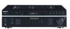
STR-DE197
US Model Canadian Model
AEP Model
AUDIO POWER SPECIFICATIONS
POWER OUTPUT AND TOTAL HARMONIC DISTORTION: (Models of ar ea code AEP Power Output a t Ster eo ...-AM RECEIVER
9-877-864-06 2007E04-1 © 2007. 05
Sony Corporation
Home Audio Division Published by Sony Techno Create Corporation
1 Amplifier section POWER OUTPUT
Models of area code US, CND Power Output ...
Service Manual - Page 2

...operated digital multimeters that is suitable for AC leakage. REPLACE THESE COMPONENTS WITH SONY...exceed 0.5 mA (500 microamperes). STR-DE197
AM tuner section Tuning range
...SONY. To reset the scale to chassis, must have a 2V AC range are subject to change the AM tuning scale to 9 kHz or 10 kHz. Measuring the voltage drop across a resistor by any AM station, turn off the receiver...
Service Manual - Page 3
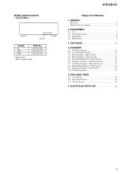
...Diagram - Schematic Diagram - Power Section 16 4-5. Panel Section 20 4-9. Schematic Diagram - Case 7 2-2. Back Panel 8 2-4. DIAGRAMS 4-1. Main Section 15 4-4. Chassis Section 25
6. BACK PANEL - Main Section (2/2 19 4-8. MODEL US AEP CND
PART No. 4-253-299-0s 4-253-299-1s 4-253-299-3s
• Abbreviation CND: Canadian model
STR-DE197
TABLE OF CONTENTS
1. Circuit...
Service Manual - Page 4

STR-DE197
SECTION 1 GENERAL
This section is extracted from instruction manual.
4
Service Manual - Page 7

CASE
1 two screws (case 3 TP2)
2 two screws (case 3 TP2)
4 case
3 two screws (case 3 TP2)
7 CASE (Page 7)
STR-DE197
2-2. FRONT PANEL SECTION 2-3. BACK PANEL
(Page 8)
(Page 8)
2-4. SET
2-1.
MAIN BOARD (Page 9)
Note : Follow the disassembly procedure in the numerical order given.
2-1. SECTION 2 DISASSEMBLY
Note : This set can be disassemble according to the following sequence.
Service Manual - Page 8

BACK PANEL
8 back panel (DE10)
2 CNP905 3 CNP901
4 three screws (BVTP3 x 8)
6 two screws (BVTP3 x 8)
7 two screws (BVTP3 x 8)
5 two screws (BVTP3 x 8)
1 connector
8 STR-DE197
2-2. FRONT PANEL SECTION
4 two screws (BVTP3 x 8) 2 CNS3
3 CNP801
6 front panel section
1 CNS2
5 six screws (BVTP3 x 8)
2-3.
Service Manual - Page 10

... step can be repeated whenever the five function buttons are tested. STR-DE197
SECTION 3 TEST MODE
Fluorescent Indicator Tube Test Mode All fluorescent segments are pressed.
• Operation of RDS station.
Procedure: 1.
ING/CHAR +] button, press the ?/1 button to turn on the main power. 2. While depressing the [VIDEO 1], [VIDEO 2], [MD/TAPE], [CD] and
the [TUNER...
Service Manual - Page 11

... only)
23 to 28
AD6 to electronic volume IC.
44
SYS.POWER
I System power signal input
45
AC MUTE
O A-Class mute signal output
46
RDS...signal input from remote control receiver IC.
50
TUNER MUTE
O Muting control signal output to the vacuum fluorescent display (FL201).
8
+5V
- Power supply pin (+5 V)
53
...
STR-DE197
4-1. A/D converter power supply pin (+5 V)
30
AV.REF
-
Service Manual - Page 12

...display (FL201).
12
O Digit drive signal output to DIG8
I/O
Pin Description
O Power relay (12V) drive signal output
O AC power relay (9V) drive signal output
O Speaker A relay (12V) drive signal output...output to the vacuum fluorescent display (FL201). Power supply pin (-24 V)
O Segment drive signal output to the vacuum fluorescent display (FL201).
- STR-DE197
Pin No. 56 57 58 59 60...
Service Manual - Page 14
...
CND : Canadian model. C
Q
These are omitted.
14 F : TUNER (FM/AM) L : VIDEO (AUDIO) J : CD (ANALOG) • Abbreviation CND : Canadian model.
BE
Q BCE
Q BCE
These are omitted. STR-DE197
THIS NOTE IS COMMON FOR PRINTED WIRING BOARDS AND SCHEMATIC DIAGRAMS. (In addition to ground
under no mark : FM • Voltages are taken with part...
Service Manual - Page 15

...34 35
49
71
X201 4.19MHz
1
REMOTE CONTROL RECEIVER
IC202
-24V
77 - 72,70 - 62 7 - 1,...SYSTEM CONTROLLER, FL DRIVER IC201
28 27 26 25 24
KEY MATRIX S204-213, 215-236, 238,239
41 42 43
CK DATA
STB
SYS.POWER...POWER RELAY
STOP SIGNAL
• Signal path : TUNER (FM/AM) : VIDEO (AUDIO) : CD (ANALOG)
• R-ch is omitted due to same as L-ch.
• Abbreviation CND : Canadian model
STR-DE197...
Service Manual - Page 16
...
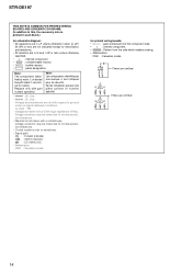
RELAY DRIVER Q903
RECT D907
RY981
T901 POWER TRANSFORMER
+B -B
AEP MODEL
-5V
3...POWER TRANSFORMER
RESET/+5.6V REG IC901
F901 F902
CNJ901 AC
OUTLET
SWITCHED 120W/1A MAX AC 120V 60 Hz (US,CND) SWITCHED 100W MAX
(AEP)
~ AC IN
• Signal path
: TUNER (FM/AM)
• R-ch is omitted due to same as L-ch.
• Abbreviation CND : Canadian model. STR-DE197
16
16 BLOCK DIAGRAM - STR-DE197...
Service Manual - Page 17
...
Q752 Q753 Q754 Q755 Q756 Q781 Q782 Q783 Q784 Q785 Q786 Q901 Q902 Q903 Q904 (Q905) (Q906)
Location
E-7 E-7 E-8 E-7 E-7 D-9 E-8 E-8 D-6 D-6 D-5 B-8 B-9 D-9 E-8 E-2 D-2
( ) : AEP model only
STR-DE197
17
17 D701 D751 D781 D782 D783 D784 D785 D786 D787 D788 D789 D901 D902 D903 D904 D905 D906
Location
D-6 D-6 E-9 C-6 C-6 D-6 D-6 E-9 E-9 D-6 D-10 B-8 B-9 D-9 B-8 B-8 B-8
Ref.
PRINTED WIRING...
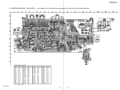
Service Manual - Page 18

...
C655
R604
R603
R653
R654
C606
C656
R929
C930
C929
(Page 19)
R942 R943
LEVEL SHIFT IC905
R945 R944
C940
R941 C941 D915
(Page 21)
STR-DE197
18
18 SCHEMATIC DIAGRAM...
Service Manual - Page 20

...
R237 R293
JW206 CNS4
(Page 17)
CN202
R270
S227
S224
TP2
R228 C218
S236
R261 CNP200
R260
R259
S235
R258
S234
R257
S233
R256
S232
STR-DE197
20
20
• Semiconductor
Location
Ref. STR-DE197
4-8. No. PRINTED WIRING BOARDS - Location
D201
C-3
D202
C-3
D203
D-3
D204
C-4
D205
B-1
D206
B-1
IC201 C-7 IC202 D-5
Q201
C-4
Q202
C-4
Q204
B-1
Q205
B-1
Q206...
Service Manual - Page 21

SCHEMATIC DIAGRAM - STR-DE197
C217
R227
C218
R228
(Page 18)
STR-DE197
IC202
CNS4
D204
FL201
C225
R237
R293
R242 C205
R294
C202
C203
C204
R238
R241
Q201
Q202 C219
R231 R232 R233 R234 R235 R236
R244
...
Service Manual - Page 23

... these items. • -XX and -X mean standardized parts, so they are not stocked since
they may have some difference from the original one. CASE SECTION 2
STR-DE197
Ver. 1.2
The components identified by mark 0 or dotted line with part number specified.
Description
X-4953-448-1 FOOT ASSY 4-232-237-01 FOOT (DIA.30) 4-977...
Service Manual - Page 24

...51
51 51 51
52 53 53 53
Part No. FRONT PANEL SECTION
55
54
not supplied
54 (POWER board)
not supplied (H. No.
54 55 56 56 * 57
* 58 59 59 FL201
Part No...54
FL201
54 59
54
not supplied
(VOLUME board)
not supplied (FUNCTION KEY board)
51
53
supplied with
RV201
52
Ref. STR-DE197
Ver. 1.2
5-2. Description
Remark
4-951-620-01 SCREW (2.6X8), +BVTP 1-773-026-11 WIRE (FLAT TYPE) (15 ...
Service Manual - Page 25

...FUSE, GLASS TUBE (DIA.5) (T2.5AL/250V) (AEP)
TRANSISTOR MN2488-OPY-M TRANSISTOR MP1620-OPY-M TRANSISTOR MN2488-OPY-M
8-749-010-26 1-443-188-11 1-443-189-11 1-693-577-13 1-693-578-13
TRANSISTOR MP1620-OPY-M TRANSFORMER, POWER (US,CND) TRANSFORMER, POWER... 0 T901
TN1 TN1
#1
Part No.
STR-DE197
5-3.
Les composants identifiés par une marque 0 sont critiques pour la sécurité.
Service Manual - Page 31

...4W
RY783 1-755-416-12 RELAY RY981 1-755-013-11 RELAY 0 RY982 1-755-276-31 RELAY, POWER
< TRANSFORMER >
Remark
5% 1W F 0 T902 1-435-281-11 TRANSFORMER, POWER (US,CND)
5% 1W F 0 T902 1-435-282-11 TRANSFORMER, POWER (AEP)
5% 1/4W
5% 1/4W F
< TERMINAL BOARD >
5% 1/4W
TM801 1-537-376-11 ...only with mark marque 0 sont critiques pour
0 are critical for safety. STR-DE197 MAIN POWER VOLUME
Ref.
Similar Questions

How To Fix Protect Mode On Sony Str-de197
How to fix protect mode on Sony Str-DE197
How to fix protect mode on Sony Str-DE197
(Posted by tweet645 3 years ago)


Str De 197 Sony
uitgang van de speakers van str de 197 gaat af en toe niet aan op het rechtse kanaalal geprobeerd of...
uitgang van de speakers van str de 197 gaat af en toe niet aan op het rechtse kanaalal geprobeerd of...
(Posted by info11711 8 years ago)

How Do I Connect An Sa-wm500 Powered Subwoofer To My Bdve570 Home Theater System
I have a Sony BDVE570 home theater system that came with a passive subwoofer.. I also have a Sony SA...
I have a Sony BDVE570 home theater system that came with a passive subwoofer.. I also have a Sony SA...
(Posted by Prit53 11 years ago)

Sony Hcd-dz120k Home Theater System
Not Operating Properly.
My Sony HCD-DZ120K home theater system isnot operating properly. On power on I get a fault message w...
My Sony HCD-DZ120K home theater system isnot operating properly. On power on I get a fault message w...
(Posted by davidberlouis 12 years ago)