
Limited Warranty (U.S. Only)
Page 1
... WARRANTY OF MERCHANTABILITY OR FITNESS FOR A PARTICULAR PURPOSE ON THIS PRODUCT IS LIMITED IN DURATION TO THE DURATION OF THIS WARRANTY. 4-557-173-02 General Stereo/Hifi Components/Tape Decks ® CD Players/Mini Disc Players/Audio Systems Hifi Audio LIMITED WARRANTY Sony Electronics Inc. ("Sony") warrants this Product is determined to be presented to obtain warranty...
... WARRANTY OF MERCHANTABILITY OR FITNESS FOR A PARTICULAR PURPOSE ON THIS PRODUCT IS LIMITED IN DURATION TO THE DURATION OF THIS WARRANTY. 4-557-173-02 General Stereo/Hifi Components/Tape Decks ® CD Players/Mini Disc Players/Audio Systems Hifi Audio LIMITED WARRANTY Sony Electronics Inc. ("Sony") warrants this Product is determined to be presented to obtain warranty...
Operating Instructions
Page 2
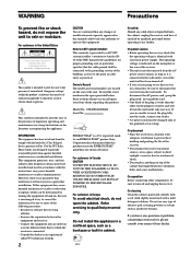
... plug itself has been turned off and unplug the receiver. Note to CATV system installer: This reminder is identical with the instructions, may be sure to radio communications. registered mark. If you are not going to use any solid object or liquid fall into an outlet on top of cable entry as alcohol or benzine. Model No. Refer servicing to direct...
... plug itself has been turned off and unplug the receiver. Note to CATV system installer: This reminder is identical with the instructions, may be sure to radio communications. registered mark. If you are not going to use any solid object or liquid fall into an outlet on top of cable entry as alcohol or benzine. Model No. Refer servicing to direct...
Operating Instructions
Page 3
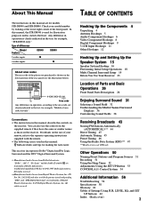
... Troubleshooting 56 Specifications 58 Glossary 61 Tables of area code CED only. For details on the use the controls on the supplied remote if they have the same or similar names as those on the receiver. TABLE OF CONTENTS Hooking Up the Components 4 Unpacking 4 Antenna Hookups 5 Audio Component Hookups 6 Video Component Hookups 8 Digital Component Hookups 9 5.1CH Input Hookups 11 Other Hookups 12 Hooking Up and Setting Up the Speaker System 15 Speaker System Hookup 16 Performing Initial Setup Operations 18 Multi Channel Surround Setup...
... Troubleshooting 56 Specifications 58 Glossary 61 Tables of area code CED only. For details on the use the controls on the supplied remote if they have the same or similar names as those on the receiver. TABLE OF CONTENTS Hooking Up the Components 4 Unpacking 4 Antenna Hookups 5 Audio Component Hookups 6 Video Component Hookups 8 Digital Component Hookups 9 5.1CH Input Hookups 11 Other Hookups 12 Hooking Up and Setting Up the Speaker System 15 Speaker System Hookup 16 Performing Initial Setup Operations 18 Multi Channel Surround Setup...
Operating Instructions
Page 6
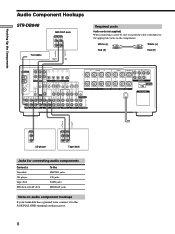
... A REAR CENTER FRONT REAR SUB WOOFER CENTER L L R L R L SPEAKERS IMPEDANCE USE 4 - 16Ω R PRE OUT IMPEDANCE 4 Ω 8 Ω SELECTOR AC OUTLET R PHONO CD MD/DAT TAPE TV/SAT DVD/LD VIDEO 2 VIDEO 1 R 2ND AUDIO OUT ç ç OUTPUT LINE L R CD player INPUT OUTPUT LINE LINE L R Tape deck Jacks for connecting audio components Connect a Turntable CD player Tape deck MD deck or DAT deck To the PHONO jacks CD jacks TAPE jacks MD/DAT jacks Note on audio component hookups If your turntable has a ground wire, connect it to the appropriate jacks on the receiver...
... A REAR CENTER FRONT REAR SUB WOOFER CENTER L L R L R L SPEAKERS IMPEDANCE USE 4 - 16Ω R PRE OUT IMPEDANCE 4 Ω 8 Ω SELECTOR AC OUTLET R PHONO CD MD/DAT TAPE TV/SAT DVD/LD VIDEO 2 VIDEO 1 R 2ND AUDIO OUT ç ç OUTPUT LINE L R CD player INPUT OUTPUT LINE LINE L R Tape deck Jacks for connecting audio components Connect a Turntable CD player Tape deck MD deck or DAT deck To the PHONO jacks CD jacks TAPE jacks MD/DAT jacks Note on audio component hookups If your turntable has a ground wire, connect it to the appropriate jacks on the receiver...
Operating Instructions
Page 7
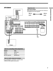
... A REAR CENTER FRONT REAR SUB WOOFER CENTER L L R L R L SPEAKERS IMPEDANCE USE 4 - 16Ω R PRE OUT IMPEDANCE 4 Ω 8 Ω SELECTOR AC OUTLET R PHONO CD MD/TAPE TV/SAT DVD/LD VIDEO 2 R VIDEO 1 OUTPUT LINE L R CD player Jacks for connecting audio components Connect a Turntable CD player MD deck or tape deck To the PHONO jacks CD jacks MD/TAPE jacks Note on audio component hookups If your turntable has a ground wire, connect it to the appropriate jacks on the receiver. 7 Hooking Up the Components ç STR-DB840 Turntable MD/Tape deck INPUT OUTPUT LINE...
... A REAR CENTER FRONT REAR SUB WOOFER CENTER L L R L R L SPEAKERS IMPEDANCE USE 4 - 16Ω R PRE OUT IMPEDANCE 4 Ω 8 Ω SELECTOR AC OUTLET R PHONO CD MD/TAPE TV/SAT DVD/LD VIDEO 2 R VIDEO 1 OUTPUT LINE L R CD player Jacks for connecting audio components Connect a Turntable CD player MD deck or tape deck To the PHONO jacks CD jacks MD/TAPE jacks Note on audio component hookups If your turntable has a ground wire, connect it to the appropriate jacks on the receiver. 7 Hooking Up the Components ç STR-DB840 Turntable MD/Tape deck INPUT OUTPUT LINE...
Operating Instructions
Page 8
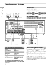
... Up the Components Video Component Hookups TV or satellite tuner OUTPUT AUDIO OUT R L VIDEO OUT DVD or LD player OUTPUT AUDIO OUT R L VIDEO OUT Required cords Audio/video cords (not supplied) When connecting a cord, be sure to match the color-coded pins to the audio from the video signals and will not be connected via an S-video jack. IN L MONITOR IN OUT IN OUT IN AUDIO IN AUDIO IN AUDIO AUDIO OUT IN AUDIO OUT AUDIO IN CONTROL A1 L FRONT A REAR CENTER FRONT REAR SUB WOOFER CENTER L L R L R L SPEAKERS IMPEDANCE USE 4 - 16Ω R PRE OUT...
... Up the Components Video Component Hookups TV or satellite tuner OUTPUT AUDIO OUT R L VIDEO OUT DVD or LD player OUTPUT AUDIO OUT R L VIDEO OUT Required cords Audio/video cords (not supplied) When connecting a cord, be sure to match the color-coded pins to the audio from the video signals and will not be connected via an S-video jack. IN L MONITOR IN OUT IN OUT IN AUDIO IN AUDIO IN AUDIO AUDIO OUT IN AUDIO OUT AUDIO IN CONTROL A1 L FRONT A REAR CENTER FRONT REAR SUB WOOFER CENTER L L R L R L SPEAKERS IMPEDANCE USE 4 - 16Ω R PRE OUT...
Operating Instructions
Page 9
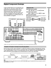
...player (etc.)* OUTPUT VIDEO OUT Required cords Optical digital cords (not supplied) Black Black Coaxial digital cord (not supplied) Yellow Yellow Audio/video cords (not supplied) When connecting a cord, be sure to this unit's digital input jacks. IN L MONITOR IN OUT IN OUT IN AUDIO AUDIO IN IN AUDIO AUDIO OUT IN AUDIO OUT AUDIO IN CONTROL A1 L FRONT A REAR CENTER FRONT REAR SUB WOOFER CENTER L L R L R L SPEAKERS IMPEDANCE USE 4 - 16Ω R PRE OUT IMPEDANCE 4 Ω 8 Ω SELECTOR AC OUTLET R PHONO CD MD/DAT TAPE TV/SAT DVD/LD VIDEO 2 VIDEO...
...player (etc.)* OUTPUT VIDEO OUT Required cords Optical digital cords (not supplied) Black Black Coaxial digital cord (not supplied) Yellow Yellow Audio/video cords (not supplied) When connecting a cord, be sure to this unit's digital input jacks. IN L MONITOR IN OUT IN OUT IN AUDIO AUDIO IN IN AUDIO AUDIO OUT IN AUDIO OUT AUDIO IN CONTROL A1 L FRONT A REAR CENTER FRONT REAR SUB WOOFER CENTER L L R L R L SPEAKERS IMPEDANCE USE 4 - 16Ω R PRE OUT IMPEDANCE 4 Ω 8 Ω SELECTOR AC OUTLET R PHONO CD MD/DAT TAPE TV/SAT DVD/LD VIDEO 2 VIDEO...

Operating Instructions
Page 10
...IN AUDIO AUDIO OUT IN AUDIO OUT AUDIO IN CONTROL A1 L FRONT A REAR CENTER FRONT REAR SUB WOOFER CENTER L L R L R L SPEAKERS IMPEDANCE USE 4 - 16Ω R PRE OUT IMPEDANCE 4 Ω 8 Ω SELECTOR AC OUTLET R PHONO CD MD/DAT TAPE TV/SAT DVD/LD VIDEO 2 VIDEO 1 R 2ND AUDIO OUT Notes • Please note that you to make analog connections. ç ç Hooking Up the Components Digital Component Hookups Connect the digital output jacks of your MD or DAT deck to the receiver's digital input jack and connect the digital input jacks of your CD player and...
...IN AUDIO AUDIO OUT IN AUDIO OUT AUDIO IN CONTROL A1 L FRONT A REAR CENTER FRONT REAR SUB WOOFER CENTER L L R L R L SPEAKERS IMPEDANCE USE 4 - 16Ω R PRE OUT IMPEDANCE 4 Ω 8 Ω SELECTOR AC OUTLET R PHONO CD MD/DAT TAPE TV/SAT DVD/LD VIDEO 2 VIDEO 1 R 2ND AUDIO OUT Notes • Please note that you to make analog connections. ç ç Hooking Up the Components Digital Component Hookups Connect the digital output jacks of your MD or DAT deck to the receiver's digital input jack and connect the digital input jacks of your CD player and...
Operating Instructions
Page 11
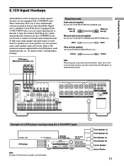
... connect them directly to this receiver incorporates a multi channel decoder, it is equipped with 5.1CH INPUT jacks. L CENTER R FRONT REAR SUB WOOFER 5.1CH OUTPUT Required cords Audio cords (not supplied) Two for the 5.1CH INPUT FRONT and REAR jacks White (L) Red (R) White (L) Red (R) Monaural audio cords (not supplied) Two for the 5.1CH INPUT CENTER and SUB WOOFER jacks Black Black Video cord (not supplied) One for the DVD/LD VIDEO IN jacks (etc.) Yellow Yellow Note When using the connections described below, adjust the level of a DVD player hookup using...
... connect them directly to this receiver incorporates a multi channel decoder, it is equipped with 5.1CH INPUT jacks. L CENTER R FRONT REAR SUB WOOFER 5.1CH OUTPUT Required cords Audio cords (not supplied) Two for the 5.1CH INPUT FRONT and REAR jacks White (L) Red (R) White (L) Red (R) Monaural audio cords (not supplied) Two for the 5.1CH INPUT CENTER and SUB WOOFER jacks Black Black Video cord (not supplied) One for the DVD/LD VIDEO IN jacks (etc.) Yellow Yellow Note When using the connections described below, adjust the level of a DVD player hookup using...
Operating Instructions
Page 12
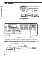
...CENTER FRONT REAR SUB WOOFER CENTER L L R L R L SPEAKERS IMPEDANCE USE 4 - 16Ω R PRE OUT IMPEDANCE 4 Ω 8 Ω SELECTOR AC OUTLET R PHONO CD MD/DAT TAPE TV/SAT DVD/LD VIDEO 2 VIDEO 1 R 2ND AUDIO OUT 2ND AUDIO OUT (STR-DB940 only) b To a wall outlet * The configuration, shape, and number of AC outlets on the components. Main room Sub room ?/1 4 • • • • 5 • • • 6• • 3 7 AUDIO AUDIO 2 8 OUT IN R Speaker (L) - + - + 1 0 • • • 9 10 Stereo amplifier...
...CENTER FRONT REAR SUB WOOFER CENTER L L R L R L SPEAKERS IMPEDANCE USE 4 - 16Ω R PRE OUT IMPEDANCE 4 Ω 8 Ω SELECTOR AC OUTLET R PHONO CD MD/DAT TAPE TV/SAT DVD/LD VIDEO 2 VIDEO 1 R 2ND AUDIO OUT 2ND AUDIO OUT (STR-DB940 only) b To a wall outlet * The configuration, shape, and number of AC outlets on the components. Main room Sub room ?/1 4 • • • • 5 • • • 6• • 3 7 AUDIO AUDIO 2 8 OUT IN R Speaker (L) - + - + 1 0 • • • 9 10 Stereo amplifier...
Operating Instructions
Page 18
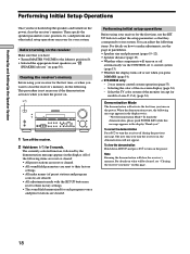
... display. Hooking Up and Setting Up the Speaker System Performing Initial Setup Operations Once you have : • Turned MASTER VOLUME to the leftmost position (0). • Selected the appropriate front speakers (see "wj SPEAKERS selector" on page 30). Select the TV color system of the monitor (except for each program source and preset stations are reset to their factory settings. • The sound field memorized for models of the on-screen display (page 54). - Clearing the receiver...
... display. Hooking Up and Setting Up the Speaker System Performing Initial Setup Operations Once you have : • Turned MASTER VOLUME to the leftmost position (0). • Selected the appropriate front speakers (see "wj SPEAKERS selector" on page 30). Select the TV color system of the monitor (except for each program source and preset stations are reset to their factory settings. • The sound field memorized for models of the on-screen display (page 54). - Clearing the receiver...

Operating Instructions
Page 22
... each speaker. Hooking Up and Setting Up the Speaker System Multi Channel Surround Setup z About speaker distances This unit allows you to input the speaker position in the LEVEL menu (see page 39). • To adjust the balance of the rear right and rear left speakers, use the rear balance parameter in terms of distance. You will sound like it a try! * Models of area code U, CA only. And they can not be output when the receiver...
... each speaker. Hooking Up and Setting Up the Speaker System Multi Channel Surround Setup z About speaker distances This unit allows you to input the speaker position in the LEVEL menu (see page 39). • To adjust the balance of the rear right and rear left speakers, use the rear balance parameter in terms of distance. You will sound like it a try! * Models of area code U, CA only. And they can not be output when the receiver...
Operating Instructions
Page 26
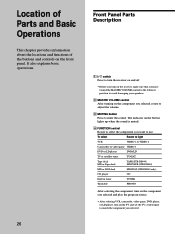
... light VCR VIDEO 1 or VIDEO 2 Camcorder or video game VIDEO 3 DVD or LD player DVD/LD TV or satellite tuner TV/SAT Tape deck MD or Tape deck TAPE (STR-DB940) MD/TAPE (STR-DB840) MD or DAT deck MD/DAT (STR-DB940 only) CD player CD Built in tuner TUNER Turntable PHONO After selecting the component, turn on the component you selected and play the program source. • After selecting VCR, camcorder, video game, DVD player, or LD player, turn on the receiver, make sure that you have turned the MASTER VOLUME control...
... light VCR VIDEO 1 or VIDEO 2 Camcorder or video game VIDEO 3 DVD or LD player DVD/LD TV or satellite tuner TV/SAT Tape deck MD or Tape deck TAPE (STR-DB940) MD/TAPE (STR-DB840) MD or DAT deck MD/DAT (STR-DB940 only) CD player CD Built in tuner TUNER Turntable PHONO After selecting the component, turn on the component you selected and play the program source. • After selecting VCR, camcorder, video game, DVD player, or LD player, turn on the receiver, make sure that you have turned the MASTER VOLUME control...
Operating Instructions
Page 27
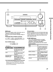
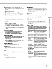
...]* selected component T When 5.1CH INPUT is set to select a different video (V:XXX) or audio (A:XXX) source, the video function lights green and the audio function lights orange. FM MODE S-VIDEO VIDEO L AUDIO R + EQUALIZER SET UP LEVEL - This also occurs when you press the button, the display changes as the main FUNCTION control** ** Even if 2ND AUDIO [SOURCE] is selected, no digital signals, analog is used to 5.1CH INPUT. 1 2 ?/1 SPEAKERS OFF• A• •B A+B • PHONES DIMMER DISPLAY MULTI CHANNEL DECODING BASS BOOST FM / AM SHIFT PRESET -
...]* selected component T When 5.1CH INPUT is set to select a different video (V:XXX) or audio (A:XXX) source, the video function lights green and the audio function lights orange. FM MODE S-VIDEO VIDEO L AUDIO R + EQUALIZER SET UP LEVEL - This also occurs when you press the button, the display changes as the main FUNCTION control** ** Even if 2ND AUDIO [SOURCE] is selected, no digital signals, analog is used to 5.1CH INPUT. 1 2 ?/1 SPEAKERS OFF• A• •B A+B • PHONES DIMMER DISPLAY MULTI CHANNEL DECODING BASS BOOST FM / AM SHIFT PRESET -
Operating Instructions
Page 28
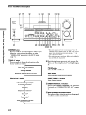
... DISPLAY MULTI CHANNEL DECODING BASS BOOST FM / AM SHIFT PRESET - When you have been entered, or it is the same as follows: v Index name of the component v Selected component v Sound field applied to the program source * Index name appears only when you want to adjust the brightness of Parts and Basic Amplifier Operations Front Panel Parts Description 67 8 9 q; A B C A.F.D. 2 CH - buttons Scans all preset stations. 9 CINEMA STUDIO EX. For details, see "CINEMA STUDIO EX. FM MODE S-VIDEO VIDEO L AUDIO R + EQUALIZER SET...
... DISPLAY MULTI CHANNEL DECODING BASS BOOST FM / AM SHIFT PRESET - When you have been entered, or it is the same as follows: v Index name of the component v Selected component v Sound field applied to the program source * Index name appears only when you want to adjust the brightness of Parts and Basic Amplifier Operations Front Panel Parts Description 67 8 9 q; A B C A.F.D. 2 CH - buttons Scans all preset stations. 9 CINEMA STUDIO EX. For details, see "CINEMA STUDIO EX. FM MODE S-VIDEO VIDEO L AUDIO R + EQUALIZER SET...
Operating Instructions
Page 29
... parameters. Crossover frequency* Specify the front, center, and rear speaker bass crossover frequency (page 22). Auto Function Specify whether or not Sony components connected via Control A1 cords will turn off response to open the door on -screen (STR-DB940 only) display (page 54). Color system Select the TV color system of the monitor. (STR-DB940 of area codes other than U, CA) OSD color Specify the color of Parts and Basic Amplifier Operations qa Use these buttons to output sound from only...
... parameters. Crossover frequency* Specify the front, center, and rear speaker bass crossover frequency (page 22). Auto Function Specify whether or not Sony components connected via Control A1 cords will turn off response to open the door on -screen (STR-DB940 only) display (page 54). Color system Select the TV color system of the monitor. (STR-DB940 of area codes other than U, CA) OSD color Specify the color of Parts and Basic Amplifier Operations qa Use these buttons to output sound from only...
Operating Instructions
Page 36
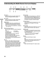
... center and rear speakers are set to indicate the channels being played does not contain the LFE channel signal. Lights when Dolby Digital (AC-3) signals are input. The letters "L.F.E." While this indicator is a digital signal being played contains the LFE (Low Frequency Effect) channel. S.WOOFER STEREO RDS MEMORY MPEGDTSDUAL PRO LOGIC LS S RS D.RANGE EQ MONO TA NEWS INFO qa 09 8 1 OPTICAL Lights up when the source signal is a digital signal being input through the OPTICAL terminal. 2 COAXIAL Lights up to playback the channels. light up when DTS signals...
... center and rear speakers are set to indicate the channels being played does not contain the LFE channel signal. Lights when Dolby Digital (AC-3) signals are input. The letters "L.F.E." While this indicator is a digital signal being played contains the LFE (Low Frequency Effect) channel. S.WOOFER STEREO RDS MEMORY MPEGDTSDUAL PRO LOGIC LS S RS D.RANGE EQ MONO TA NEWS INFO qa 09 8 1 OPTICAL Lights up when the source signal is a digital signal being input through the OPTICAL terminal. 2 COAXIAL Lights up to playback the channels. light up when DTS signals...
Operating Instructions
Page 51
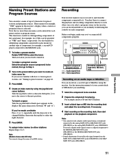
... . To record a digital audio signal, connect a digital component to the DIGITAL MD/DAT OUT jacks (STR-DB940) or the DIGITAL MD/TAPE OUT jacks (STR-DB840). • Sound adjustments do not affect the signal output from the components connected to Step 3. 2 Tune in the receiver's display when a station or program source is between "??" To index a program source Select the program source (component) to be specified as you need help. 1 Select the component to create an index name for identifying components connected to select the tuner. To assign index names to...
... . To record a digital audio signal, connect a digital component to the DIGITAL MD/DAT OUT jacks (STR-DB940) or the DIGITAL MD/TAPE OUT jacks (STR-DB840). • Sound adjustments do not affect the signal output from the components connected to Step 3. 2 Tune in the receiver's display when a station or program source is between "??" To index a program source Select the program source (component) to be specified as you need help. 1 Select the component to create an index name for identifying components connected to select the tuner. To assign index names to...
Operating Instructions
Page 57
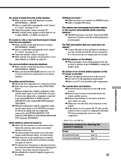
... receiver. , Set your TV away from the center speaker. , Make sure the sound field function is set the tuning interval correctly (when tuning in with a FUNCTION button. , When recording from a digital component, make sure the input mode is set to operate the TV only, use the remote to the appropriate input mode. , Move your TV to select a source or component other component. * Models of front speakers. MODE). , Make sure that the antennas are connected correctly. , Select the source component with automatic tuning). Adjust the antennas and connect...
... receiver. , Set your TV away from the center speaker. , Make sure the sound field function is set the tuning interval correctly (when tuning in with a FUNCTION button. , When recording from a digital component, make sure the input mode is set to operate the TV only, use the remote to the appropriate input mode. , Move your TV to select a source or component other component. * Models of front speakers. MODE). , Make sure that the antennas are connected correctly. , Select the source component with automatic tuning). Adjust the antennas and connect...
Operating Instructions
Page 64
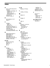
... H Hookups 5.1 CH input 11 AC power cord 14 antennas 5 audio components 6, 7 digital components 9, 10 CONTROL A1 II 13 S-LINK CONTROL S 13 speaker system 16 video components 8 I, J, K Indexing. See Automatic tuning Selecting component 26 front speaker system 30 sound field 32 Sleep timer 52 Sound field adjustable parameters 41, 42 customizing 38~42 pre-programmed 33~35 resetting 41 selecting 32 Speakers adjusting speaker volume 22 connection 16 impedance 17 placement 19~22 Supplied accessories 4 Surround sound 31~42 T Test tone 22 Tuning automatically 45 directly 45 preset stations 46...
... H Hookups 5.1 CH input 11 AC power cord 14 antennas 5 audio components 6, 7 digital components 9, 10 CONTROL A1 II 13 S-LINK CONTROL S 13 speaker system 16 video components 8 I, J, K Indexing. See Automatic tuning Selecting component 26 front speaker system 30 sound field 32 Sleep timer 52 Sound field adjustable parameters 41, 42 customizing 38~42 pre-programmed 33~35 resetting 41 selecting 32 Speakers adjusting speaker volume 22 connection 16 impedance 17 placement 19~22 Supplied accessories 4 Surround sound 31~42 T Test tone 22 Tuning automatically 45 directly 45 preset stations 46...


