
Limited Warranty (U.S. Only)
Page 1
... factory applied serial number has been altered or removed from the date of protection, to you . REPAIR OR REPLACEMENT AS PROVIDED UNDER THIS WARRANTY IS THE EXCLUSIVE REMEDY OF THE CONSUMER. 4-557-173-02 General Stereo/Hifi Components/Tape Decks ® CD Players/Mini Disc Players/Audio Systems Hifi Audio LIMITED WARRANTY Sony Electronics Inc. ("Sony") warrants this Product is valid only in material or workmanship as fuses or batteries). PARTS...
... factory applied serial number has been altered or removed from the date of protection, to you . REPAIR OR REPLACEMENT AS PROVIDED UNDER THIS WARRANTY IS THE EXCLUSIVE REMEDY OF THE CONSUMER. 4-557-173-02 General Stereo/Hifi Components/Tape Decks ® CD Players/Mini Disc Players/Audio Systems Hifi Audio LIMITED WARRANTY Sony Electronics Inc. ("Sony") warrants this Product is valid only in material or workmanship as fuses or batteries). PARTS...
Operating Instructions
Page 3
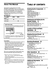
... 5 Audio Component Hookups 6 Video Component Hookups 8 Digital Component Hookups 9 5.1CH Input Hookups 11 Other Hookups 12 Hooking Up and Setting Up the Speaker System 15 Speaker System Hookup 16 Performing Initial Setup Operations 18 Multi Channel Surround Setup 19 Before You Use Your Receiver 23 Location of Parts and Basic Operations 26 Front Panel Parts Description 26 Enjoying Surround Sound 31 Selecting a Sound Field 32 Understanding the Multi-Channel Surround Displays 36 Customizing Sound Fields 38 Receiving Broadcasts 43 Storing FM Stations Automatically (AUTOBETICAL)*** 44 Direct...
... 5 Audio Component Hookups 6 Video Component Hookups 8 Digital Component Hookups 9 5.1CH Input Hookups 11 Other Hookups 12 Hooking Up and Setting Up the Speaker System 15 Speaker System Hookup 16 Performing Initial Setup Operations 18 Multi Channel Surround Setup 19 Before You Use Your Receiver 23 Location of Parts and Basic Operations 26 Front Panel Parts Description 26 Enjoying Surround Sound 31 Selecting a Sound Field 32 Understanding the Multi-Channel Surround Displays 36 Customizing Sound Fields 38 Receiving Broadcasts 43 Storing FM Stations Automatically (AUTOBETICAL)*** 44 Direct...
Operating Instructions
Page 5
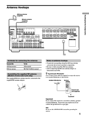
... IN AUDIO AUDIO IN IN AUDIO AUDIO OUT IN AUDIO OUT AUDIO IN CONTROL A1 L FRONT A REAR CENTER FRONT REAR SUB WOOFER CENTER L L R L R L SPEAKERS IMPEDANCE USE 4 - 16Ω R PRE OUT IMPEDANCE 4 Ω 8 Ω SELECTOR AC OUTLET R PHONO CD MD/DAT TAPE TV/SAT DVD/LD VIDEO 2 VIDEO 1 R 2ND AUDIO OUT Terminals for grounding the receiver. 5 FM COA7X5IΩAL Notes on antenna hookups • To prevent noise pickup, keep it against lightning. Hooking Up the Components Antenna Hookups AM loop antenna (supplied) FM wire antenna (supplied) ANTENNA...
... IN AUDIO AUDIO IN IN AUDIO AUDIO OUT IN AUDIO OUT AUDIO IN CONTROL A1 L FRONT A REAR CENTER FRONT REAR SUB WOOFER CENTER L L R L R L SPEAKERS IMPEDANCE USE 4 - 16Ω R PRE OUT IMPEDANCE 4 Ω 8 Ω SELECTOR AC OUTLET R PHONO CD MD/DAT TAPE TV/SAT DVD/LD VIDEO 2 VIDEO 1 R 2ND AUDIO OUT Terminals for grounding the receiver. 5 FM COA7X5IΩAL Notes on antenna hookups • To prevent noise pickup, keep it against lightning. Hooking Up the Components Antenna Hookups AM loop antenna (supplied) FM wire antenna (supplied) ANTENNA...
Operating Instructions
Page 6
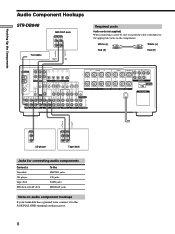
... A REAR CENTER FRONT REAR SUB WOOFER CENTER L L R L R L SPEAKERS IMPEDANCE USE 4 - 16Ω R PRE OUT IMPEDANCE 4 Ω 8 Ω SELECTOR AC OUTLET R PHONO CD MD/DAT TAPE TV/SAT DVD/LD VIDEO 2 VIDEO 1 R 2ND AUDIO OUT ç ç OUTPUT LINE L R CD player INPUT OUTPUT LINE LINE L R Tape deck Jacks for connecting audio components Connect a Turntable CD player Tape deck MD deck or DAT deck To the PHONO jacks CD jacks TAPE jacks MD/DAT jacks Note on audio component hookups If your turntable has a ground wire, connect it to the appropriate jacks on the receiver...
... A REAR CENTER FRONT REAR SUB WOOFER CENTER L L R L R L SPEAKERS IMPEDANCE USE 4 - 16Ω R PRE OUT IMPEDANCE 4 Ω 8 Ω SELECTOR AC OUTLET R PHONO CD MD/DAT TAPE TV/SAT DVD/LD VIDEO 2 VIDEO 1 R 2ND AUDIO OUT ç ç OUTPUT LINE L R CD player INPUT OUTPUT LINE LINE L R Tape deck Jacks for connecting audio components Connect a Turntable CD player Tape deck MD deck or DAT deck To the PHONO jacks CD jacks TAPE jacks MD/DAT jacks Note on audio component hookups If your turntable has a ground wire, connect it to the appropriate jacks on the receiver...
Operating Instructions
Page 7
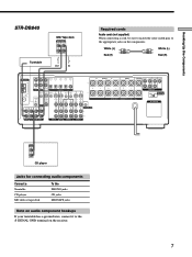
...FRONT A REAR CENTER FRONT REAR SUB WOOFER CENTER L L R L R L SPEAKERS IMPEDANCE USE 4 - 16Ω R PRE OUT IMPEDANCE 4 Ω 8 Ω SELECTOR AC OUTLET R PHONO CD MD/TAPE TV/SAT DVD/LD VIDEO 2 R VIDEO 1 OUTPUT LINE L R CD player Jacks for connecting audio components Connect a Turntable CD player MD deck or tape deck To the PHONO jacks CD jacks MD/TAPE jacks Note on audio component hookups If your turntable has a ground wire, connect it to the appropriate jacks on the receiver. 7 Hooking Up the Components ç STR-DB840 Turntable MD/Tape deck INPUT OUTPUT LINE...
...FRONT A REAR CENTER FRONT REAR SUB WOOFER CENTER L L R L R L SPEAKERS IMPEDANCE USE 4 - 16Ω R PRE OUT IMPEDANCE 4 Ω 8 Ω SELECTOR AC OUTLET R PHONO CD MD/TAPE TV/SAT DVD/LD VIDEO 2 R VIDEO 1 OUTPUT LINE L R CD player Jacks for connecting audio components Connect a Turntable CD player MD deck or tape deck To the PHONO jacks CD jacks MD/TAPE jacks Note on audio component hookups If your turntable has a ground wire, connect it to the appropriate jacks on the receiver. 7 Hooking Up the Components ç STR-DB840 Turntable MD/Tape deck INPUT OUTPUT LINE...
Operating Instructions
Page 8
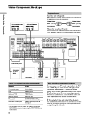
... you can display the SURROUND, LEVEL, EQUALIZER parameters by pressing the ON SCREEN button on the remote. 8 Note on a separate bus from the TV. IN L MONITOR IN OUT IN OUT IN AUDIO IN AUDIO IN AUDIO AUDIO OUT IN AUDIO OUT AUDIO IN CONTROL A1 L FRONT A REAR CENTER FRONT REAR SUB WOOFER CENTER L L R L R L SPEAKERS IMPEDANCE USE 4 - 16Ω R PRE OUT IMPEDANCE 4 Ω 8 Ω SELECTOR AC OUTLET R PHONO CD MD/DAT TAPE TV/SAT DVD/LD VIDEO 2 VIDEO 1 R 2ND AUDIO OUT To the...
... you can display the SURROUND, LEVEL, EQUALIZER parameters by pressing the ON SCREEN button on the remote. 8 Note on a separate bus from the TV. IN L MONITOR IN OUT IN OUT IN AUDIO IN AUDIO IN AUDIO AUDIO OUT IN AUDIO OUT AUDIO IN CONTROL A1 L FRONT A REAR CENTER FRONT REAR SUB WOOFER CENTER L L R L R L SPEAKERS IMPEDANCE USE 4 - 16Ω R PRE OUT IMPEDANCE 4 Ω 8 Ω SELECTOR AC OUTLET R PHONO CD MD/DAT TAPE TV/SAT DVD/LD VIDEO 2 VIDEO 1 R 2ND AUDIO OUT To the...
Operating Instructions
Page 9
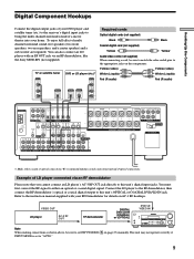
... Components Digital Component Hookups Connect the digital output jacks of your DVD player and satellite tuner (etc.) to the receiver's digital input jacks to bring the multi channel surround sound of multi channel surround sound, five speakers (two front speakers, two rear speakers, and a center speaker) and a sub woofer are required. Connect the LD player to the RF demodulator, then connect the RF demodulator's optical or coaxial digital output to this unit's digital input jacks. TV or satellite tuner OUTPUT VIDEO OUT DVD or LD player (etc.)* OUTPUT VIDEO OUT Required cords...
... Components Digital Component Hookups Connect the digital output jacks of your DVD player and satellite tuner (etc.) to the receiver's digital input jacks to bring the multi channel surround sound of multi channel surround sound, five speakers (two front speakers, two rear speakers, and a center speaker) and a sub woofer are required. Connect the LD player to the RF demodulator, then connect the RF demodulator's optical or coaxial digital output to this unit's digital input jacks. TV or satellite tuner OUTPUT VIDEO OUT DVD or LD player (etc.)* OUTPUT VIDEO OUT Required cords...

Operating Instructions
Page 10
... frequencies. The other jacks may result in intermittent sound. 10 To record digital signals, make digital connections. • Input signals with 96 kHz sampling frequencies to TAPE and VIDEO with your DVD (or LD player) and satellite broadcasts. IN L MONITOR IN OUT IN OUT IN AUDIO AUDIO IN IN AUDIO AUDIO OUT IN AUDIO OUT AUDIO IN CONTROL A1 L FRONT A REAR CENTER FRONT REAR SUB WOOFER CENTER L L R L R L SPEAKERS IMPEDANCE USE 4 - 16Ω R PRE OUT IMPEDANCE 4 Ω 8 Ω SELECTOR AC OUTLET R PHONO CD MD/DAT TAPE...
... frequencies. The other jacks may result in intermittent sound. 10 To record digital signals, make digital connections. • Input signals with 96 kHz sampling frequencies to TAPE and VIDEO with your DVD (or LD player) and satellite broadcasts. IN L MONITOR IN OUT IN OUT IN AUDIO AUDIO IN IN AUDIO AUDIO OUT IN AUDIO OUT AUDIO IN CONTROL A1 L FRONT A REAR CENTER FRONT REAR SUB WOOFER CENTER L L R L R L SPEAKERS IMPEDANCE USE 4 - 16Ω R PRE OUT IMPEDANCE 4 Ω 8 Ω SELECTOR AC OUTLET R PHONO CD MD/DAT TAPE...
Operating Instructions
Page 11
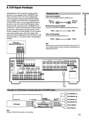
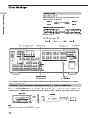
... CENTER FRONT REAR SUB WOOFER CENTER L L R L R L SPEAKERS IMPEDANCE USE 4 - 16Ω R PRE OUT IMPEDANCE 4 Ω 8 Ω SELECTOR AC OUTLET R PHONO CD MD/DAT TAPE TV/SAT DVD/LD VIDEO 2 VIDEO 1 R 2ND AUDIO OUT Example of a DVD player hookup using the connections described below, adjust the level of the DVD player's multi channel decoder. To fully enjoy multi channel surround sound, you to enjoy multichannel software encoded in formats other than Dolby Digital (AC-3) and DTS. ANTENNA AM L MD/DAT MD/DAT TV/SAT DVD/LD DVD/LD OPTICAL OPTICAL OPTICAL OPTICAL COAXIAL...
... CENTER FRONT REAR SUB WOOFER CENTER L L R L R L SPEAKERS IMPEDANCE USE 4 - 16Ω R PRE OUT IMPEDANCE 4 Ω 8 Ω SELECTOR AC OUTLET R PHONO CD MD/DAT TAPE TV/SAT DVD/LD VIDEO 2 VIDEO 1 R 2ND AUDIO OUT Example of a DVD player hookup using the connections described below, adjust the level of the DVD player's multi channel decoder. To fully enjoy multi channel surround sound, you to enjoy multichannel software encoded in formats other than Dolby Digital (AC-3) and DTS. ANTENNA AM L MD/DAT MD/DAT TV/SAT DVD/LD DVD/LD OPTICAL OPTICAL OPTICAL OPTICAL COAXIAL...
Operating Instructions
Page 12
... REAR SUB WOOFER CENTER L L R L R L SPEAKERS IMPEDANCE USE 4 - 16Ω R PRE OUT IMPEDANCE 4 Ω 8 Ω SELECTOR AC OUTLET R PHONO CD MD/DAT TAPE TV/SAT DVD/LD VIDEO 2 VIDEO 1 R 2ND AUDIO OUT 2ND AUDIO OUT (STR-DB940 only) b To a wall outlet * The configuration, shape, and number of AC outlets on pages 26 and 27) to switch the audio signal output to the sub room. Use MODE and FUNCTION (4 on the rear panel varies according to the model and country to a stereo amplifier...
... REAR SUB WOOFER CENTER L L R L R L SPEAKERS IMPEDANCE USE 4 - 16Ω R PRE OUT IMPEDANCE 4 Ω 8 Ω SELECTOR AC OUTLET R PHONO CD MD/DAT TAPE TV/SAT DVD/LD VIDEO 2 VIDEO 1 R 2ND AUDIO OUT 2ND AUDIO OUT (STR-DB940 only) b To a wall outlet * The configuration, shape, and number of AC outlets on pages 26 and 27) to switch the audio signal output to the sub room. Use MODE and FUNCTION (4 on the rear panel varies according to the model and country to a stereo amplifier...
Operating Instructions
Page 18
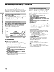
... ?/1 to turn on the receiver Make sure that they correspond to their factory settings. • The sound field memorized for 5 seconds. All of area U, CA) (page 54). Hooking Up and Setting Up the Speaker System Performing Initial Setup Operations Once you !" For details on -screen display (page 54). - Thank you have : • Turned MASTER VOLUME to make adjustments, see the page in the display. The currently selected function, followed...
... ?/1 to turn on the receiver Make sure that they correspond to their factory settings. • The sound field memorized for 5 seconds. All of area U, CA) (page 54). Hooking Up and Setting Up the Speaker System Performing Initial Setup Operations Once you !" For details on -screen display (page 54). - Thank you have : • Turned MASTER VOLUME to make adjustments, see the page in the display. The currently selected function, followed...

Operating Instructions
Page 22
... screen. Note This unit incorporates a new test tone with a frequency centered at the same time Rotate MASTER VOLUME on the remote. 4 Press TEST TONE again to 180 Hz. Note The test tone cannot be output when the receiver is set the center speaker further than the front speakers. Also, the center speaker cannot be no more that speaker. Adjusting these parameter while listening to 5.1CH INPUT. x Rear speaker crossover frequency (REAR SP >) Initial setting : 120 Hz Lets you adjust the rear speaker bass crossover frequency when...
... screen. Note This unit incorporates a new test tone with a frequency centered at the same time Rotate MASTER VOLUME on the remote. 4 Press TEST TONE again to 180 Hz. Note The test tone cannot be output when the receiver is set the center speaker further than the front speakers. Also, the center speaker cannot be no more that speaker. Adjusting these parameter while listening to 5.1CH INPUT. x Rear speaker crossover frequency (REAR SP >) Initial setting : 120 Hz Lets you adjust the rear speaker bass crossover frequency when...
Operating Instructions
Page 26
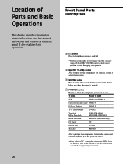
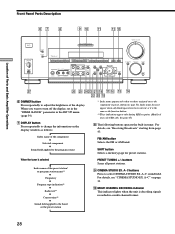
... adjust the volume. 3 MUTING button Press to mute the sound. To select Rotate to light VCR VIDEO 1 or VIDEO 2 Camcorder or video game VIDEO 3 DVD or LD player DVD/LD TV or satellite tuner TV/SAT Tape deck MD or Tape deck TAPE (STR-DB940) MD/TAPE (STR-DB840) MD or DAT deck MD/DAT (STR-DB940 only) CD player CD Built in tuner TUNER Turntable PHONO After selecting the component, turn on the component you selected and play the program source. • After selecting VCR, camcorder, video game, DVD player...
... adjust the volume. 3 MUTING button Press to mute the sound. To select Rotate to light VCR VIDEO 1 or VIDEO 2 Camcorder or video game VIDEO 3 DVD or LD player DVD/LD TV or satellite tuner TV/SAT Tape deck MD or Tape deck TAPE (STR-DB940) MD/TAPE (STR-DB840) MD or DAT deck MD/DAT (STR-DB940 only) CD player CD Built in tuner TUNER Turntable PHONO After selecting the component, turn on the component you selected and play the program source. • After selecting VCR, camcorder, video game, DVD player...
Operating Instructions
Page 27
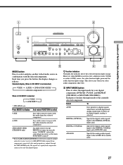
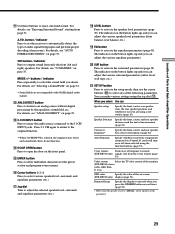
Each time you select audio components (like CD). 5 INPUT MODE button Press to the AUDIO IN (L and R) jacks 27 Each press switches the input mode of Parts and Basic Amplifier Operations 5 4 3 MODE button Press to only the digital inputs. A B C A.F.D. 2 CH - MODE + VIDEO 3 INPUT MEMORY - Only signals from components connected to select and play another video/audio source in your digital components (DVD/LD, TV/SAT, and MD/DAT (STR-DB940) or MD/TAPE (STR-DB840)). SUR INPUT MODE NAME EQ ANLG DIRECT 5.1CH INPUT + MASTER VOLUME 4 • • • •...
Each time you select audio components (like CD). 5 INPUT MODE button Press to the AUDIO IN (L and R) jacks 27 Each press switches the input mode of Parts and Basic Amplifier Operations 5 4 3 MODE button Press to only the digital inputs. A B C A.F.D. 2 CH - MODE + VIDEO 3 INPUT MEMORY - Only signals from components connected to select and play another video/audio source in your digital components (DVD/LD, TV/SAT, and MD/DAT (STR-DB940) or MD/TAPE (STR-DB840)). SUR INPUT MODE NAME EQ ANLG DIRECT 5.1CH INPUT + MASTER VOLUME 4 • • • •...
Operating Instructions
Page 28
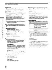
... the function button. ** These indications appear only during RDS reception. (Models of the preset station* or program station name** v Frequency v Program type indication** v Radio text** v Current time** v Sound field applied to turn off the display, set in the "DIMM. RANGE" parameter in the SET UP menu (page 54). 7 DISPLAY button Press repeatedly to change the information on page 33. 0 MULTI CHANNEL DECODING indicator This indicator lights when the unit is decoding signals recorded in tuner. A~C sound field...
... the function button. ** These indications appear only during RDS reception. (Models of the preset station* or program station name** v Frequency v Program type indication** v Radio text** v Current time** v Sound field applied to turn off the display, set in the "DIMM. RANGE" parameter in the SET UP menu (page 54). 7 DISPLAY button Press repeatedly to change the information on page 33. 0 MULTI CHANNEL DECODING indicator This indicator lights when the unit is decoding signals recorded in tuner. A~C sound field...
Operating Instructions
Page 29
... Sony components connected via Control A1 cords will turn off response to remote (STR-DB940 only) signals sent from the 2 way remote (page 53). For details, see "ANALOG DIRECT" on or off when you press the DIMMER button several times (page 54). * Only when the speaker is selected, the equalizer, bass boost, and sound field effects do not function. qf DOOR OPEN button Press to automatically detect the type of audio signal being input...
... Sony components connected via Control A1 cords will turn off response to remote (STR-DB940 only) signals sent from the 2 way remote (page 53). For details, see "ANALOG DIRECT" on or off when you press the DIMMER button several times (page 54). * Only when the speaker is selected, the equalizer, bass boost, and sound field effects do not function. qf DOOR OPEN button Press to automatically detect the type of audio signal being input...
Operating Instructions
Page 30
... equalizer is improved. Models of area code CED TUNING/PTY SELECT +/- For details, see "Receiving Broadcasts" starting from page 47. FM MODE button If "STEREO" flashes in the display and the FM stereo reception is set to activate the name function and enter names for preset stations and program sources (page 51). Selecting other sound fields when the SPEAKERS selector is poor, press this case, set the IMPEDANCE SELECTOR to "4Ω" PHONES jack Connects headphones. • To use...
... equalizer is improved. Models of area code CED TUNING/PTY SELECT +/- For details, see "Receiving Broadcasts" starting from page 47. FM MODE button If "STEREO" flashes in the display and the FM stereo reception is set to activate the name function and enter names for preset stations and program sources (page 51). Selecting other sound fields when the SPEAKERS selector is poor, press this case, set the IMPEDANCE SELECTOR to "4Ω" PHONES jack Connects headphones. • To use...
Operating Instructions
Page 51
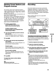
... . It is useful for example, a second CD player connected to the MD/DAT jacks. 1 To index a preset station Rotate FUNCTION to the next position. Recording Your receiver makes it . Playback component (program source) l: Audio signal flow .: Video signal flow Recording component (tape deck, MD deck, VCR) Recording on an audio tape or MiniDisc You can record on a cassette tape or MiniDisc using the jog dial and cursor buttons: Turn the jog dial to select a character, then...
... . It is useful for example, a second CD player connected to the MD/DAT jacks. 1 To index a preset station Rotate FUNCTION to the next position. Recording Your receiver makes it . Playback component (program source) l: Audio signal flow .: Video signal flow Recording component (tape deck, MD deck, VCR) Recording on an audio tape or MiniDisc You can record on a cassette tape or MiniDisc using the jog dial and cursor buttons: Turn the jog dial to select a character, then...
Operating Instructions
Page 57
... the antennas are connected correctly. , Select the source component with a FUNCTION button. , When recording from a digital component, make sure the input mode is set to ANALOG (see page 27) before recording with a component connected to the analog MD/DAT or TAPE terminals (STR-DB940) or the analog MD/TAPE terminals (STR-DB840). , When recording from a digital component, make sure the input mode is activated. Use direct tuning. , Make sure you select the correct function on the remote. , If the remote is on the receiver...
... the antennas are connected correctly. , Select the source component with a FUNCTION button. , When recording from a digital component, make sure the input mode is set to ANALOG (see page 27) before recording with a component connected to the analog MD/DAT or TAPE terminals (STR-DB940) or the analog MD/TAPE terminals (STR-DB840). , When recording from a digital component, make sure the input mode is activated. Use direct tuning. , Make sure you select the correct function on the remote. , If the remote is on the receiver...
Operating Instructions
Page 64
... cord 14 antennas 5 audio components 6, 7 digital components 9, 10 CONTROL A1 II 13 S-LINK CONTROL S 13 speaker system 16 video components 8 I, J, K Indexing. See Preset tuning radio stations. See Dolby Digital (AC-3) Adjusting brightness of the display 28 equalizer 40 speaker volumes 22 surround parameters 38 Autobetical 44 Automatic tuning 45 B Basic operations 26~30 Battery 4 C Changing display 28 effect level 38 Checking the connections 23 Clearing receiver's memory 18 Connecting 4~14 Crossover frequency 22 Customizing sound fields 38~42 D Digital Cinema Sound 61 Dimmer Range 54 Direct...
... cord 14 antennas 5 audio components 6, 7 digital components 9, 10 CONTROL A1 II 13 S-LINK CONTROL S 13 speaker system 16 video components 8 I, J, K Indexing. See Preset tuning radio stations. See Dolby Digital (AC-3) Adjusting brightness of the display 28 equalizer 40 speaker volumes 22 surround parameters 38 Autobetical 44 Automatic tuning 45 B Basic operations 26~30 Battery 4 C Changing display 28 effect level 38 Checking the connections 23 Clearing receiver's memory 18 Connecting 4~14 Crossover frequency 22 Customizing sound fields 38~42 D Digital Cinema Sound 61 Dimmer Range 54 Direct...


