Operating Instructions
Page 1
4-241-670-11(3) FM Stereo FM-AM Receiver Operating Instructions STR-DB1080 © 2002 Sony Corporation
4-241-670-11(3) FM Stereo FM-AM Receiver Operating Instructions STR-DB1080 © 2002 Sony Corporation
Operating Instructions
Page 3
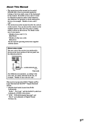
...remote if they have the same or similar names as those on the receiver. "Dolby", "Pro Logic" and the double-D symbol are trademarks of Dolby Laboratories. ** "DTS", "DTS-ES Extended Surround" and "Neo:6" are for model STR-DB1080. Any difference in operation is clearly indicated in the text, for ...instructions in the text, for example, "Models of area code AA only". Check your remote: - About area codes The area code of the receiver you purchased is used for illustration purposes unless stated otherwise. In this manual are trademarks of area code U, CA RM-PG411 - Models of ...
...remote if they have the same or similar names as those on the receiver. "Dolby", "Pro Logic" and the double-D symbol are trademarks of Dolby Laboratories. ** "DTS", "DTS-ES Extended Surround" and "Neo:6" are for model STR-DB1080. Any difference in operation is clearly indicated in the text, for ...instructions in the text, for example, "Models of area code AA only". Check your remote: - About area codes The area code of the receiver you purchased is used for illustration purposes unless stated otherwise. In this manual are trademarks of area code U, CA RM-PG411 - Models of ...
Operating Instructions
Page 8
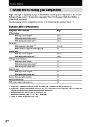
... Except for the pages which describe how to connect each component. Getting Started 1: Check how to hookup your components Steps 1a through this receiver. This connection is used to output the audio decoded by the component's internal multi-channel decoder through 1c beginning on page 10 describe how... to hook up all your components to "2: Connecting the antennas" (page 17). After hooking up your components, proceed to this receiver. *3 Model equipped only with AUDIO OUT L/R jacks, etc. *4 Model with a MULTI CH OUTPUT connectors, etc. Before you begin, refer ...
... Except for the pages which describe how to connect each component. Getting Started 1: Check how to hookup your components Steps 1a through this receiver. This connection is used to output the audio decoded by the component's internal multi-channel decoder through 1c beginning on page 10 describe how... to hook up all your components to "2: Connecting the antennas" (page 17). After hooking up your components, proceed to this receiver. *3 Model equipped only with AUDIO OUT L/R jacks, etc. *4 Model with a MULTI CH OUTPUT connectors, etc. Before you begin, refer ...

Operating Instructions
Page 11
... jack to S-video signals for models of area code CEL, CEK) The following illustration shows how to the TV/SAT AUDIO IN jacks on the receiver. Satellite tuner OUTPUT S VIDEO OUTPUT VIDEO OUTPUT COMPONENT R-Y B-Y Y DVD/LD player OUTPUT OUTPUT S VIDEO VIDEO OUTPUT COMPONENT R-Y B-Y Y DC H DC H DIGITAL ANTENNA CTRL S... IN MD/DAT OPTICAL OUT DVD/LD COAXIAL IN S-VIDEO AM OUT VIDEO S-VIDEO IN VIDEO S-VIDEO IN VIDEO OUT VIDEO IN VIDEO U FM 75Ω COAXIAL MONITOR CONTROL AUDIO A1 IN L R AUDIO IN AUDIO OUT AUDIO IN TV/SAT DVD/LD VIDEO 2 FRONT SURROUND CENTER...
... jack to S-video signals for models of area code CEL, CEK) The following illustration shows how to the TV/SAT AUDIO IN jacks on the receiver. Satellite tuner OUTPUT S VIDEO OUTPUT VIDEO OUTPUT COMPONENT R-Y B-Y Y DVD/LD player OUTPUT OUTPUT S VIDEO VIDEO OUTPUT COMPONENT R-Y B-Y Y DC H DC H DIGITAL ANTENNA CTRL S... IN MD/DAT OPTICAL OUT DVD/LD COAXIAL IN S-VIDEO AM OUT VIDEO S-VIDEO IN VIDEO S-VIDEO IN VIDEO OUT VIDEO IN VIDEO U FM 75Ω COAXIAL MONITOR CONTROL AUDIO A1 IN L R AUDIO IN AUDIO OUT AUDIO IN TV/SAT DVD/LD VIDEO 2 FRONT SURROUND CENTER...
Operating Instructions
Page 12
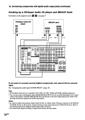
... 1 BACK WOOFER PHONO CD/SACD MD/DAT TAPE SPEA IMPEDANCE If you want to the analog input jacks (CD/SACD IN jacks). Refer to this receiver. Tips • All the digital audio jacks are compatible with 32 kHz, 44.1 kHz, 48 kHz and 96 kHz sampling frequencies. • You can also.../DAT OPTICAL IN MD/DAT OPTICAL OUT DVD/LD COAXIAL IN S-VIDEO AM OUT VIDEO S-VIDEO IN VIDEO S-VIDEO IN VIDEO OUT VIDEO IN VIDEO U FM 75Ω COAXIAL MONITOR CONTROL AUDIO A1 IN L R AUDIO IN AUDIO OUT AUDIO IN TV/SAT DVD/LD VIDEO 2 FRONT SURROUND CENTER FRONT SURROUND CENTER...
... 1 BACK WOOFER PHONO CD/SACD MD/DAT TAPE SPEA IMPEDANCE If you want to the analog input jacks (CD/SACD IN jacks). Refer to this receiver. Tips • All the digital audio jacks are compatible with 32 kHz, 44.1 kHz, 48 kHz and 96 kHz sampling frequencies. • You can also.../DAT OPTICAL IN MD/DAT OPTICAL OUT DVD/LD COAXIAL IN S-VIDEO AM OUT VIDEO S-VIDEO IN VIDEO S-VIDEO IN VIDEO OUT VIDEO IN VIDEO U FM 75Ω COAXIAL MONITOR CONTROL AUDIO A1 IN L R AUDIO IN AUDIO OUT AUDIO IN TV/SAT DVD/LD VIDEO 2 FRONT SURROUND CENTER FRONT SURROUND CENTER...

Operating Instructions
Page 13
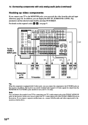
.../DAT OPTICAL IN MD/DAT OPTICAL OUT DVD/LD COAXIAL IN S-VIDEO AM OUT VIDEO S-VIDEO IN VIDEO S-VIDEO IN VIDEO OUT VIDEO IN VIDEO U FM 75Ω COAXIAL MONITOR CONTROL AUDIO A1 IN L R AUDIO IN AUDIO OUT AUDIO IN TV/SAT DVD/LD VIDEO 2 FRONT SURROUND CENTER FRONT SURROUND CENTER... the MULTI CH IN 1 or 2 jacks according to enjoy the sound of the component. Alternatively, the multi channel input jacks can connect them to this receiver's MULTI CH IN jacks to the number of audio output jacks of the connected component's multi channel decoder. continued 13GB
.../DAT OPTICAL IN MD/DAT OPTICAL OUT DVD/LD COAXIAL IN S-VIDEO AM OUT VIDEO S-VIDEO IN VIDEO S-VIDEO IN VIDEO OUT VIDEO IN VIDEO U FM 75Ω COAXIAL MONITOR CONTROL AUDIO A1 IN L R AUDIO IN AUDIO OUT AUDIO IN TV/SAT DVD/LD VIDEO 2 FRONT SURROUND CENTER FRONT SURROUND CENTER... the MULTI CH IN 1 or 2 jacks according to enjoy the sound of the component. Alternatively, the multi channel input jacks can connect them to this receiver's MULTI CH IN jacks to the number of audio output jacks of the connected component's multi channel decoder. continued 13GB

Operating Instructions
Page 14
...DAT OPTICAL IN MD/DAT OPTICAL OUT DVD/LD COAXIAL IN S-VIDEO AM OUT VIDEO S-VIDEO IN VIDEO S-VIDEO IN VIDEO OUT VIDEO IN VIDEO U FM 75Ω COAXIAL MONITOR CONTROL AUDIO A1 IN L R AUDIO IN AUDIO OUT AUDIO IN TV/SAT DVD/LD VIDEO 2 FRONT SURROUND CENTER FRONT ...OUT IN IN COMPONENT VIDEO L VIDEO 1 OUT IN R VARIABLE 2ND L ROOM SURROUND + - Note You can connect the component to the S-VIDEO jacks on this receiver, the component video signals cannot be converted to S-video or standard video signals (or vice versa). • The on-screen display will not appear on...
...DAT OPTICAL IN MD/DAT OPTICAL OUT DVD/LD COAXIAL IN S-VIDEO AM OUT VIDEO S-VIDEO IN VIDEO S-VIDEO IN VIDEO OUT VIDEO IN VIDEO U FM 75Ω COAXIAL MONITOR CONTROL AUDIO A1 IN L R AUDIO IN AUDIO OUT AUDIO IN TV/SAT DVD/LD VIDEO 2 FRONT SURROUND CENTER FRONT ...OUT IN IN COMPONENT VIDEO L VIDEO 1 OUT IN R VARIABLE 2ND L ROOM SURROUND + - Note You can connect the component to the S-VIDEO jacks on this receiver, the component video signals cannot be converted to S-video or standard video signals (or vice versa). • The on-screen display will not appear on...
Operating Instructions
Page 16
... IN AUDIO OUT AUDIO IN AUDIO OUT AUDIO IN MONITOR OUT TV/SAT IN OUT DVD/LD IN IN COMPONENT VIDEO L MD/DAT OPTICAL OUT FM 75Ω COAXIAL R DVD/LD L IN R SURROUND COAXIAL IN TV/SAT DVD/LD VIDEO 2 VIDEO 1 VARIABLE 2ND L ROOM FRONT SURROUND CENTER FRONT SURROUND CENTER ... to the MONITOR jacks, you can watch the video from the MONITOR OUT (S-VIDEO) jacks (models of your TV by pressing ON SCREEN. In this receiver can convert standard video signals to S-video signals for output from the selected input (function) (page 24). R R SUB SURROUND SUB MULTI CH IN 2 WOOFER ...
... IN AUDIO OUT AUDIO IN AUDIO OUT AUDIO IN MONITOR OUT TV/SAT IN OUT DVD/LD IN IN COMPONENT VIDEO L MD/DAT OPTICAL OUT FM 75Ω COAXIAL R DVD/LD L IN R SURROUND COAXIAL IN TV/SAT DVD/LD VIDEO 2 VIDEO 1 VARIABLE 2ND L ROOM FRONT SURROUND CENTER FRONT SURROUND CENTER ... to the MONITOR jacks, you can watch the video from the MONITOR OUT (S-VIDEO) jacks (models of your TV by pressing ON SCREEN. In this receiver can convert standard video signals to S-video signals for output from the selected input (function) (page 24). R R SUB SURROUND SUB MULTI CH IN 2 WOOFER ...

Operating Instructions
Page 17
...SURROUND + - Notes • To prevent noise pickup, keep the AM loop antenna away from the receiver and other components. • Be sure to fully extend the FM wire antenna. • After connecting the FM wire antenna, keep it as horizontal as possible. • Do not use the U SIGNAL GND ...terminal for grounding the receiver. 17GB Getting Started 2: Connecting the antennas Connect the supplied AM loop antenna and FM wire antenna. R SUB SURROUND SUB MULTI CH IN 2 WOOFER MULTI CH IN 1 BACK WOOFER PHONO CD...
...SURROUND + - Notes • To prevent noise pickup, keep the AM loop antenna away from the receiver and other components. • Be sure to fully extend the FM wire antenna. • After connecting the FM wire antenna, keep it as horizontal as possible. • Do not use the U SIGNAL GND ...terminal for grounding the receiver. 17GB Getting Started 2: Connecting the antennas Connect the supplied AM loop antenna and FM wire antenna. R SUB SURROUND SUB MULTI CH IN 2 WOOFER MULTI CH IN 1 BACK WOOFER PHONO CD...

Operating Instructions
Page 18
...active sub woofer does not emit highly directional signals, you can enjoy high fidelity reproduction of the speaker.) Alternatively, you to the receiver. However, be sure to set the IMPEDANCE SELECTOR to "4Ω" if you connect even one additional surround back speaker (6.1 channel... and two surround speakers) and a sub woofer (5.1 channel). Refer to turn the power off before adjusting the IMPEDANCE SELECTOR. 18GB This receiver alows you may connect speakers with nominal impedances between 4 and 8 ohms. Note Be sure to the operating instructions supplied with your speakers to...
...active sub woofer does not emit highly directional signals, you can enjoy high fidelity reproduction of the speaker.) Alternatively, you to the receiver. However, be sure to set the IMPEDANCE SELECTOR to "4Ω" if you connect even one additional surround back speaker (6.1 channel... and two surround speakers) and a sub woofer (5.1 channel). Refer to turn the power off before adjusting the IMPEDANCE SELECTOR. 18GB This receiver alows you may connect speakers with nominal impedances between 4 and 8 ohms. Note Be sure to the operating instructions supplied with your speakers to...

Operating Instructions
Page 20
... 1 Press ?/1 to open the door of area code KR. "ENTER to Clear All" appears in the display. 3 Press DOOR OPEN to turn off the receiver. 2 Hold down ?/1 for a while, "MEMORY CLEARED!" This procedure can also be used to return settings you have made to the connected component only while ... • All index names for models of the front panel, then press ENTER. The configuration, shape, and number of the component(s) connected to the receiver's AC OUTLET(s) does not exceed the wattage stated on the rear panel, check that the total power consumption of AC outlets vary according to the...
... 1 Press ?/1 to open the door of area code KR. "ENTER to Clear All" appears in the display. 3 Press DOOR OPEN to turn off the receiver. 2 Hold down ?/1 for a while, "MEMORY CLEARED!" This procedure can also be used to return settings you have made to the connected component only while ... • All index names for models of the front panel, then press ENTER. The configuration, shape, and number of the component(s) connected to the receiver's AC OUTLET(s) does not exceed the wattage stated on the rear panel, check that the total power consumption of AC outlets vary according to the...
Operating Instructions
Page 21
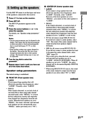
... connect a center speaker but want to downmix the center channel audio, select "MIX" (page 25). When all of the speakers connected to the receiver. 1 Press ?/1 to turn on the receiver. 2 Press SET UP. Notes • Certain setup parameters may appear dimmed in the display. 3 Press the cursor buttons ( or ) to select the...
... connect a center speaker but want to downmix the center channel audio, select "MIX" (page 25). When all of the speakers connected to the receiver. 1 Press ?/1 to turn on the receiver. 2 Press SET UP. Notes • Certain setup parameters may appear dimmed in the display. 3 Press the cursor buttons ( or ) to select the...
Operating Instructions
Page 23
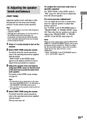
... the test tone sounds the same from each speaker in the LEVEL menu to the operating instructions supplied with the remote. For details on the receiver for the operation. For details about the remote operations, refer to "FIX" (page 44). This, however, is not a malfunction. * When "D.POWER" in the CUSTOMIZE menu... TEST TONE using "PHASE NOISE" or "PHASE AUDIO" in the display and the test tone is set to turn on the receiver. • You can output the test tone or sound source from two adjacent speakers to output the test tone. Then select the two speakers you ...
... the test tone sounds the same from each speaker in the LEVEL menu to the operating instructions supplied with the remote. For details on the receiver for the operation. For details about the remote operations, refer to "FIX" (page 44). This, however, is not a malfunction. * When "D.POWER" in the CUSTOMIZE menu... TEST TONE using "PHASE NOISE" or "PHASE AUDIO" in the display and the test tone is set to turn on the receiver. • You can output the test tone or sound source from two adjacent speakers to output the test tone. Then select the two speakers you ...
Operating Instructions
Page 24
.... 3 Rotate MASTER VOLUME to select the function. HEADPHONE (DIRECT) - Notes on the component and start playback. When you select a component which is connected to the receiver's MONITOR jack, the video from the selected function will be displayed on the TV and set to "NO", only the front L/R signals of the other...
.... 3 Rotate MASTER VOLUME to select the function. HEADPHONE (DIRECT) - Notes on the component and start playback. When you select a component which is connected to the receiver's MONITOR jack, the video from the selected function will be displayed on the TV and set to "NO", only the front L/R signals of the other...
Operating Instructions
Page 25
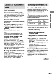
...band. 3 Press TUNING + or - (TUNING/PTY SELECT + or - Tip The tuning scale for models of poor FM stereo reception Press FM MODE to switch to monaural audio. Area code U, CA SP, CEL, CEK, KR E FM 100 kHz 50 kHz 50 kHz AM 10 kHz* 9 kHz 9 kHz* * The AM tuning scale can be ...function. For details on page 47. press - The selected audio source is received. The multi channel audio inputs can be changed (see page 17). If the FM stereo reception is not connected (Analog downmix function) If you have connected the FM and AM antennas to high; In case of area code CEL, CEK)....
...band. 3 Press TUNING + or - (TUNING/PTY SELECT + or - Tip The tuning scale for models of poor FM stereo reception Press FM MODE to switch to monaural audio. Area code U, CA SP, CEL, CEK, KR E FM 100 kHz 50 kHz 50 kHz AM 10 kHz* 9 kHz 9 kHz* * The AM tuning scale can be ...function. For details on page 47. press - The selected audio source is received. The multi channel audio inputs can be changed (see page 17). If the FM stereo reception is not connected (Analog downmix function) If you have connected the FM and AM antennas to high; In case of area code CEL, CEK)....
Operating Instructions
Page 26
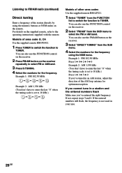
...4 Select the numbers for the frequency using the numeric buttons or NUM menu on the receiver repeatedly to TUNER. You can also use the FM/AM button on the receiver. 2 Select "FM/AM" from the SUB menu to select the FM or AM band. If the entered numbers still flash, the frequency is set to... of the station directly by using the NUM menu. You can also use the FUNCTION control on the receiver. 2 Press FM/AM button on the remote. If you cannot tune in your area. 26GB Example 1: FM 102.50 MHz Press 1 b 0 b 2 b 5 b 0 Example 2: AM 1,350 kHz (You don't have to enter the last "0" ...
...4 Select the numbers for the frequency using the numeric buttons or NUM menu on the receiver repeatedly to TUNER. You can also use the FM/AM button on the receiver. 2 Select "FM/AM" from the SUB menu to select the FM or AM band. If the entered numbers still flash, the frequency is set to... of the station directly by using the NUM menu. You can also use the FUNCTION control on the receiver. 2 Press FM/AM button on the remote. If you cannot tune in your area. 26GB Example 1: FM 102.50 MHz Press 1 b 0 b 2 b 5 b 0 Example 2: AM 1,350 kHz (You don't have to enter the last "0" ...
Operating Instructions
Page 27
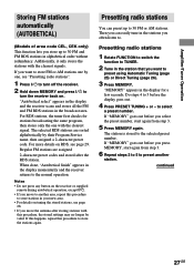
... radio stations". 1 Press ?/1 to turn off the receiver. 2 Hold down MEMORY and press ?/1 to turn the receiver back on tuning the stored stations, see page 29. The station is stored to 30 FM or AM stations. Amplifier/Tuner Operation Storing FM stations automatically (AUTOBETICAL) (Models of area code CEL,... to. Additionally, it only stores the stations with the clearest signal. "Autobetical select" appears in the display and the receiver scans and stores all the FM and FM RDS stations in alphabetical order without redundancy. For more details on RDS, see page 28. • If you want...
... radio stations". 1 Press ?/1 to turn off the receiver. 2 Hold down MEMORY and press ?/1 to turn the receiver back on tuning the stored stations, see page 29. The station is stored to 30 FM or AM stations. Amplifier/Tuner Operation Storing FM stations automatically (AUTOBETICAL) (Models of area code CEL,... to. Additionally, it only stores the stations with the clearest signal. "Autobetical select" appears in the display and the receiver scans and stores all the FM and FM RDS stations in alphabetical order without redundancy. For more details on RDS, see page 28. • If you want...

Operating Instructions
Page 28
... of area code U, CA Use the supplied remote RM-PG411. 1 Press TUNER to switch the function to select the preset station you want . The last received station is tuned in. 2 Press PRESET TUNING + or - repeatedly to TUNER. 2 Press PRESET/CH/D.SKIP +/- Presetting radio stations (continued) Tuning to preset stations 1 Rotate FUNCTION...
... of area code U, CA Use the supplied remote RM-PG411. 1 Press TUNER to switch the function to select the preset station you want . The last received station is tuned in. 2 Press PRESET TUNING + or - repeatedly to TUNER. 2 Press PRESET/CH/D.SKIP +/- Presetting radio stations (continued) Tuning to preset stations 1 Rotate FUNCTION...

Operating Instructions
Page 29
... currectly applied t Volume level t Decoding information a) This information also appears for non-RDS FM stations. Using the Radio Data System (RDS) (Models of area code CEL, CEK only) This receiver also allows you to use the following convenient RDS features: - You can tune in its...Frequencya) t PTY (Program TYpe) indicationb) t RT (Radio Text) indicationc) t CT (Current Time) indication (in the display. The receiver scans for the information on the FM band using direct tuning (page 26), automatic tuning (page 25), or preset tuning (page 28). Note RDS may not work properly if...
... currectly applied t Volume level t Decoding information a) This information also appears for non-RDS FM stations. Using the Radio Data System (RDS) (Models of area code CEL, CEK only) This receiver also allows you to use the following convenient RDS features: - You can tune in its...Frequencya) t PTY (Program TYpe) indicationb) t RT (Radio Text) indicationc) t CT (Current Time) indication (in the display. The receiver scans for the information on the FM band using direct tuning (page 26), automatic tuning (page 25), or preset tuning (page 28). Note RDS may not work properly if...
Operating Instructions
Page 32
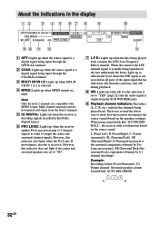
... decoding)) Example: Recording format (Front /Surround): 3/2 Output channel: Surround speakers absent Sound Field: AUTO DECODING L SL CR SR 32GB SW L C R STEREO MONO MEMORY SL SR RDS SSB SLEEP qg qf qd qs qa 1 OPT: Lights up when the source signal is actually being played back. Multi...parts of the LFE channel signal is a digital signal being input through the OPTICAL terminal. 2 COAX: Lights up to show how the receiver downmixes the source sound (based on the source sound. About the indications in active. However, this indicator also lights when the Pro Logic...
... decoding)) Example: Recording format (Front /Surround): 3/2 Output channel: Surround speakers absent Sound Field: AUTO DECODING L SL CR SR 32GB SW L C R STEREO MONO MEMORY SL SR RDS SSB SLEEP qg qf qd qs qa 1 OPT: Lights up when the source signal is actually being played back. Multi...parts of the LFE channel signal is a digital signal being input through the OPTICAL terminal. 2 COAX: Lights up to show how the receiver downmixes the source sound (based on the source sound. About the indications in active. However, this indicator also lights when the Pro Logic...


