Dimensions Diagrams
Page 1
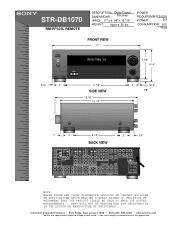
STR-DB1070 RM-PP505L REMOTE DESCRIPTION: Dolby Digital DIMENSIONS Receiver (WHD): 17" x 6 1/4" x 15 7/8" WEIGHT: Approx 35 lbs POWER REQUIREMENTS:120V POWER 60H CONSUMPTION: 300 Watts FRONT VIEW 17" R FM102.7MHz A3 VIDEO 3 5 5/8" 6 1/4" 9/16" 2 " 11 7/8" ...• Non-metric weights and measurements are approximate. SONY WILL NOT BE RESPONSIBLE FOR INACCURACIES IN THE DESIGN OR MANUFACTURE OF ENCLOSURES . CTRL-S S-VIDEO S-VIDEO CTRL-S CTRL-S S-VIDEO S-VIDEO CTRL-S VIDEO IN IN IN OUT OUT OUT IN IN OUT COAXIAL CONTROL A1 ll FM COAX FRONT REAR CNT FRONT REAR TV/SAT...
STR-DB1070 RM-PP505L REMOTE DESCRIPTION: Dolby Digital DIMENSIONS Receiver (WHD): 17" x 6 1/4" x 15 7/8" WEIGHT: Approx 35 lbs POWER REQUIREMENTS:120V POWER 60H CONSUMPTION: 300 Watts FRONT VIEW 17" R FM102.7MHz A3 VIDEO 3 5 5/8" 6 1/4" 9/16" 2 " 11 7/8" ...• Non-metric weights and measurements are approximate. SONY WILL NOT BE RESPONSIBLE FOR INACCURACIES IN THE DESIGN OR MANUFACTURE OF ENCLOSURES . CTRL-S S-VIDEO S-VIDEO CTRL-S CTRL-S S-VIDEO S-VIDEO CTRL-S VIDEO IN IN IN OUT OUT OUT IN IN OUT COAXIAL CONTROL A1 ll FM COAX FRONT REAR CNT FRONT REAR TV/SAT...
Service Manual
Page 2
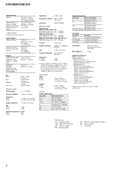
... 11.2 dBf, 1 µV/75 ohms S/N Mono: Stereo: 76 dB 70 dB Harmonic distortion at 1 kHz Mono: 0.3% Stereo: 0.5% Separation 45 dB at 1 kHz Frequency response 30...controls 16.0 kg Supplied accessories FM wire antenna (1) AM loop antenna (1) • Models of area code U, CA Audio/video/control S connecting cord (1) Control S connecting cord (1) • STR-DB1070 only • Models of area code U, CA Remote...turn off the receiver. Impedance: 75 ohms S/N: 100 dB (A, 20 kHz LPF) Sensitivity: - To reset the scale to 10 kHz (or 9 kHz), repeat the procedure. STR-DB870/DB1070 Inputs (Analog...
... 11.2 dBf, 1 µV/75 ohms S/N Mono: Stereo: 76 dB 70 dB Harmonic distortion at 1 kHz Mono: 0.3% Stereo: 0.5% Separation 45 dB at 1 kHz Frequency response 30...controls 16.0 kg Supplied accessories FM wire antenna (1) AM loop antenna (1) • Models of area code U, CA Audio/video/control S connecting cord (1) Control S connecting cord (1) • STR-DB1070 only • Models of area code U, CA Remote...turn off the receiver. Impedance: 75 ohms S/N: 100 dB (A, 20 kHz LPF) Sensitivity: - To reset the scale to 10 kHz (or 9 kHz), repeat the procedure. STR-DB870/DB1070 Inputs (Analog...

Service Manual
Page 35
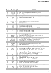
STR-DB870/DB1070 (Page 27) (Page 28) CN502 11P FSP,RY- Ne les remplacer que par une pi&#...1k R583 1k R633 1k R683 1k R733 1k (CHASSIS) C471 100p 50V C421 100p 50V C436 100p R1704 1k REMOTE CONTROL RECEIVER IC1701 NJL63H400A S1703 DISPLAY S1702 DIMMER S1704 VCC GND OUT C1701 47 16V S1701 SPEAKERS OFF ON R1703 22k R1701 ...100 R1702 10 CN1701 11P (Page 33) J402 4P L FRONT R L SURROUND R J403 1P (DB870) CENTER J401 4P (DB1070) PRE OUT L SURROUND BACK R SUB WOOFER J701 2P SUB WOOFER (DB870) CN1801 8P RV1801 ROTARY ENCODER FUNCTION (Page 33) R1803 220...
STR-DB870/DB1070 (Page 27) (Page 28) CN502 11P FSP,RY- Ne les remplacer que par une pi&#...1k R583 1k R633 1k R683 1k R733 1k (CHASSIS) C471 100p 50V C421 100p 50V C436 100p R1704 1k REMOTE CONTROL RECEIVER IC1701 NJL63H400A S1703 DISPLAY S1702 DIMMER S1704 VCC GND OUT C1701 47 16V S1701 SPEAKERS OFF ON R1703 22k R1701 ...100 R1702 10 CN1701 11P (Page 33) J402 4P L FRONT R L SURROUND R J403 1P (DB870) CENTER J401 4P (DB1070) PRE OUT L SURROUND BACK R SUB WOOFER J701 2P SUB WOOFER (DB870) CN1801 8P RV1801 ROTARY ENCODER FUNCTION (Page 33) R1803 220...
Service Manual
Page 51
...) signal input terminal (US, Canadian models only) 65 MBUS VIDEO I VIDEO (M BUS) input terminal (US, Canadian models only) 66 SIRCS I Sircs signal input from the remote control receiver (IC1701) and select switch (IC751) 67 DIR ERROR I System reset signal input from the audio DSP (IC1601) 48 NC I Not used (fixed at "L" ) 52 MD2... (D1801) 51 GND - Ground terminal 45, 46 NC I Not used (fixed at "L" ) 47 ERROR I Error signal input from the reset signal generator (IC1702) 56 VCC - STR-DB870/DB1070 Pin No.
...) signal input terminal (US, Canadian models only) 65 MBUS VIDEO I VIDEO (M BUS) input terminal (US, Canadian models only) 66 SIRCS I Sircs signal input from the remote control receiver (IC1701) and select switch (IC751) 67 DIR ERROR I System reset signal input from the audio DSP (IC1601) 48 NC I Not used (fixed at "L" ) 52 MD2... (D1801) 51 GND - Ground terminal 45, 46 NC I Not used (fixed at "L" ) 47 ERROR I Error signal input from the reset signal generator (IC1702) 56 VCC - STR-DB870/DB1070 Pin No.
Service Manual
Page 55
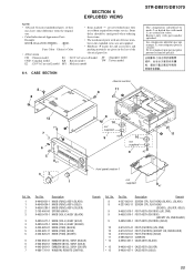
...Color Cabinet's Color packing materials are given in E model MY : Malaysia model 6-1. CASE SECTION 8 8 chassis section 11 8 B STR-DB870/DB1070 The components identified by mark 0 or dotted line with mark 0 are critical for routine service. delay should be anticipated when ordering &#... 5 4-233-626-21 KNOB (F14B) (SILVER) 6 4-942-568-41 EMBLEM (NO.5), SONY (BLACK) 6 4-942-568-51 EMBLEM (NO.5), SONY (GOLD) 6 4-942-568-61 EMBLEM (NO.5), SONY (SILVER) 7 4-980-776-01 WINDOW, REMOTE CONTROL Remark Ref. SECTION 6 EXPLODED VIEWS NOTE: • -XX and -X mean standardized parts,...
...Color Cabinet's Color packing materials are given in E model MY : Malaysia model 6-1. CASE SECTION 8 8 chassis section 11 8 B STR-DB870/DB1070 The components identified by mark 0 or dotted line with mark 0 are critical for routine service. delay should be anticipated when ordering &#... 5 4-233-626-21 KNOB (F14B) (SILVER) 6 4-942-568-41 EMBLEM (NO.5), SONY (BLACK) 6 4-942-568-51 EMBLEM (NO.5), SONY (GOLD) 6 4-942-568-61 EMBLEM (NO.5), SONY (SILVER) 7 4-980-776-01 WINDOW, REMOTE CONTROL Remark Ref. SECTION 6 EXPLODED VIEWS NOTE: • -XX and -X mean standardized parts,...
Service Manual
Page 77
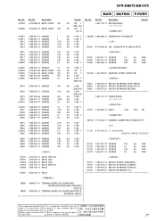
...5% 1/4W (DB1070) 5% 1/4W 1-681-101-11 POWER BOARD 5% 1/4W 5% 1/4W F < CAPACITOR > 5% 1/4W F 5% 1/4W C1701 1-104-660-11 ELECT 47uF 20% 16V 5% 1/4W 5% 1/4W F < CONNECTOR > 5% 1/4W CN1701 1-770-404-11 HOUSING, CONNECTOR (PC BOARD) 11P 5% 1/4W 5% 1/4W < IC > 5% 1/4W 5% 1/4W F IC1701 8-759-459-85 IC NJL63H400A 5% 1/4W (REMOTE CONTROL RECEIVER) R856 R859... 0 R809 1-215-889-00 METAL OXIDE 330 0 R809 1-215-890-11 METAL OXIDE 470 Remark Ref. sécurité. No. STR-DB870/DB1070 MAIN MUTING POWER Ref. portant le numéro spécifié. 77
...5% 1/4W (DB1070) 5% 1/4W 1-681-101-11 POWER BOARD 5% 1/4W 5% 1/4W F < CAPACITOR > 5% 1/4W F 5% 1/4W C1701 1-104-660-11 ELECT 47uF 20% 16V 5% 1/4W 5% 1/4W F < CONNECTOR > 5% 1/4W CN1701 1-770-404-11 HOUSING, CONNECTOR (PC BOARD) 11P 5% 1/4W 5% 1/4W < IC > 5% 1/4W 5% 1/4W F IC1701 8-759-459-85 IC NJL63H400A 5% 1/4W (REMOTE CONTROL RECEIVER) R856 R859... 0 R809 1-215-889-00 METAL OXIDE 330 0 R809 1-215-890-11 METAL OXIDE 470 Remark Ref. sécurité. No. STR-DB870/DB1070 MAIN MUTING POWER Ref. portant le numéro spécifié. 77

Operating Instructions (primary manual)
Page 3
... the multi channel surround displays 32 Customizing sound fields 33 Receiving Broadcasts Storing FM stations automatically (AUTOBETICAL 38 Direct tuning 38 Automatic tuning 39...CONTROL A1 control system ......... 47 Additional Information Precautions 49 Troubleshooting 49 Specifications 52 Tables of settings using SURR, LEVEL, EQ, and SET UP buttons 55 Adjustable parameters for each sound field 58 Remote...receiver on page 18. 3 For details on what will be cleared, see "Clearing the receiver's memory" on , the demonstration will not appear. Table of area code CEL only. ** STR...
... the multi channel surround displays 32 Customizing sound fields 33 Receiving Broadcasts Storing FM stations automatically (AUTOBETICAL 38 Direct tuning 38 Automatic tuning 39...CONTROL A1 control system ......... 47 Additional Information Precautions 49 Troubleshooting 49 Specifications 52 Tables of settings using SURR, LEVEL, EQ, and SET UP buttons 55 Adjustable parameters for each sound field 58 Remote...receiver on page 18. 3 For details on what will be cleared, see "Clearing the receiver's memory" on , the demonstration will not appear. Table of area code CEL only. ** STR...
Operating Instructions (primary manual)
Page 4
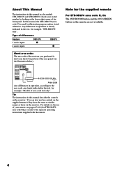
...Tip The instructions in this manual, the STR-DB1070 (area code U) is used for models STR-DB1070 and STR-DB870. For details on the use the controls on the supplied remote if they have the same or similar names as those on the remote are clearly indicated in operation, according to...separate operating instructions supplied with the remote. Any difference in the text, for the supplied remote For STR-DB870 area code U, CA The 2ND ROOM button and the ON SCREEN button on the receiver. Type of differences Feature 5 audio inputs 4 audio inputs DB1070 z DB870 z About area codes...
...Tip The instructions in this manual, the STR-DB1070 (area code U) is used for models STR-DB1070 and STR-DB870. For details on the use the controls on the supplied remote if they have the same or similar names as those on the remote are clearly indicated in operation, according to...separate operating instructions supplied with the remote. Any difference in the text, for the supplied remote For STR-DB870 area code U, CA The 2ND ROOM button and the ON SCREEN button on the receiver. Type of differences Feature 5 audio inputs 4 audio inputs DB1070 z DB870 z About area codes...
Operating Instructions (primary manual)
Page 46
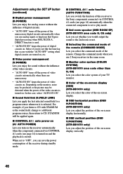
... turned on, etc. In this receiver to the Sony components connected via CONTROL A1 cords (see page 14) automatically when the connected component is started. When set to CD, STADIUM will be distorted when the power of the video circuits is selected. x OSD horizontal position (OSD H.POSITION) (STR-DB1070 only) Lets you can save the...
... turned on, etc. In this receiver to the Sony components connected via CONTROL A1 cords (see page 14) automatically when the connected component is started. When set to CD, STADIUM will be distorted when the power of the video circuits is selected. x OSD horizontal position (OSD H.POSITION) (STR-DB1070 only) Lets you can save the...

Operating Instructions (primary manual)
Page 47
... the connected component in a manner contrary to 10 CONTROL A1 compatible components in any order. Basically, the majority of the CONTROL A1 Control System. CONTROL A1 connections provide a path for the transmission of separate Sony components. For detailed information regarding specific operations, be ...functions. • Do not operate a 2 way remote control unit when the CONTROL A1 jacks are compatible with components with the respective component for each type of component (i.e., 1 CD player, 1 MD deck, 1 tape deck and 1 receiver). (You may be able to connect more than ...
... the connected component in a manner contrary to 10 CONTROL A1 compatible components in any order. Basically, the majority of the CONTROL A1 Control System. CONTROL A1 connections provide a path for the transmission of separate Sony components. For detailed information regarding specific operations, be ...functions. • Do not operate a 2 way remote control unit when the CONTROL A1 jacks are compatible with components with the respective component for each type of component (i.e., 1 CD player, 1 MD deck, 1 tape deck and 1 receiver). (You may be able to connect more than ...
Operating Instructions (primary manual)
Page 51
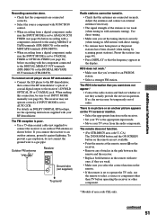
...Make sure that you set INPUT MODE manually (see page 26). continued 51 For details on the remote. • If the remote is too weak (when tuning in question. Outdoor FM antenna Receiver ANTENNA AM U FM 75Ω COAXIAL Ground wire (not supplied) To ground Radio stations cannot be tuned in AM... connect the ground wire to the receiver's DVD/LD OPTICAL IN or COAXIAL jack. There is poor. • Use a 75-ohm coaxial cable (not supplied) to connect the receiver to the analog MD/DAT or TAPE terminals (STR-DB1070) or the analog MD/TAPE terminals (STR-DB870). • When recording from...
...Make sure that you set INPUT MODE manually (see page 26). continued 51 For details on the remote. • If the remote is too weak (when tuning in question. Outdoor FM antenna Receiver ANTENNA AM U FM 75Ω COAXIAL Ground wire (not supplied) To ground Radio stations cannot be tuned in AM... connect the ground wire to the receiver's DVD/LD OPTICAL IN or COAXIAL jack. There is poor. • Use a 75-ohm coaxial cable (not supplied) to connect the receiver to the analog MD/DAT or TAPE terminals (STR-DB1070) or the analog MD/TAPE terminals (STR-DB870). • When recording from...
Operating Instructions (primary manual)
Page 54
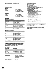
... (Approx.) 430 × 161 × 401 mm including projecting parts and controls 16.0 kg Supplied accessories FM wire antenna (1) AM loop antenna (1) • Models of area code U, CA Audio/video/control S connecting cord (1) Control S connecting cord (1) • STR-DB1070 only • Models of area code U, CA Remote commander RM-PP505L (1) R6 (size-AA) batteries (2) • Models of...
... (Approx.) 430 × 161 × 401 mm including projecting parts and controls 16.0 kg Supplied accessories FM wire antenna (1) AM loop antenna (1) • Models of area code U, CA Audio/video/control S connecting cord (1) Control S connecting cord (1) • STR-DB1070 only • Models of area code U, CA Remote commander RM-PP505L (1) R6 (size-AA) batteries (2) • Models of...


