

Limited Warranty (U.S. Only)
Page 1
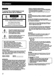
...exclusion or limitation of sale or receipted invoice which vary from your convenience, Sony Electronics Inc. 4-557-173-02 General Stereo/Hifi Components/Tape Decks ® CD Players/Mini Disc Players/Audio Systems Hifi Audio LIMITED WARRANTY Sony Electronics Inc. ("Sony") warrants this Product ...instruction, installation, set up adjustments or signal reception problems. This warranty does not cover cosmetic damage or damage due to acts of God, accident, misuse, abuse, negligence, commercial use, or modification of, or to any Sony authorized service facility. REPAIR OR REPLACEMENT...
...exclusion or limitation of sale or receipted invoice which vary from your convenience, Sony Electronics Inc. 4-557-173-02 General Stereo/Hifi Components/Tape Decks ® CD Players/Mini Disc Players/Audio Systems Hifi Audio LIMITED WARRANTY Sony Electronics Inc. ("Sony") warrants this Product ...instruction, installation, set up adjustments or signal reception problems. This warranty does not cover cosmetic damage or damage due to acts of God, accident, misuse, abuse, negligence, commercial use, or modification of, or to any Sony authorized service facility. REPAIR OR REPLACEMENT...
Operating Instructions
Page 2
... the rear exterior and serial number is marked with v or 4k, mark) must be connected to the presence of electric shock to attach the fuse cover after you change or modifications not expressly approved in this manual could void your Sony dealer regarding this equipment has a detachable fuse cover, be used . Refer to the earth terminal in Radio Interference Regulations. 2 STR-D511...
... the rear exterior and serial number is marked with v or 4k, mark) must be connected to the presence of electric shock to attach the fuse cover after you change or modifications not expressly approved in this manual could void your Sony dealer regarding this equipment has a detachable fuse cover, be used . Refer to the earth terminal in Radio Interference Regulations. 2 STR-D511...
Operating Instructions
Page 3
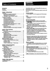
...manual show the STR-D611. 3 model) 7 Identifying the parts and controls 8 Front panel 8 Remote commander 9 Inserting the batteries into the remote commander 9 Chapter 2 Basic Operations Remote controls 10 Changing the settings of the FUNCTION buttons 10 Audio adjustment 11 Adjusting volume 11 Adjusting tone quality 11 Adjusting left and right sound balance 11 Reinforcing the bass 11 Selecting the speaker system 11 Selecting a program source 11 Receiving FM/AM broadcasts 12 Tuning in a station directly (Direct 4 -ling) 12 Automatic tuning 13 Presetting stations...
...manual show the STR-D611. 3 model) 7 Identifying the parts and controls 8 Front panel 8 Remote commander 9 Inserting the batteries into the remote commander 9 Chapter 2 Basic Operations Remote controls 10 Changing the settings of the FUNCTION buttons 10 Audio adjustment 11 Adjusting volume 11 Adjusting tone quality 11 Adjusting left and right sound balance 11 Reinforcing the bass 11 Selecting the speaker system 11 Selecting a program source 11 Receiving FM/AM broadcasts 12 Tuning in a station directly (Direct 4 -ling) 12 Automatic tuning 13 Presetting stations...
Operating Instructions
Page 4
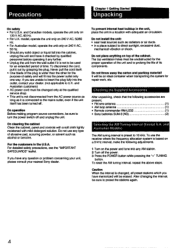
... into the outlet, contact your nearest Sony dealer. To use any AM station. 2 Turn off the power. 3 Press the POWER button while pressing the "+" TUNING button. Never pull the cord itself has been turned off and unplug the unit. and Australian customers) • AC power cord must be used for the proper operation of the unit and to turn the power switch off . For detailed safety precautions, see...
... into the outlet, contact your nearest Sony dealer. To use any AM station. 2 Turn off the power. 3 Press the POWER button while pressing the "+" TUNING button. Never pull the cord itself has been turned off and unplug the unit. and Australian customers) • AC power cord must be used for the proper operation of the unit and to turn the power switch off . For detailed safety precautions, see...
Operating Instructions
Page 5
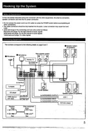
... right channel of audio signals White jacks and plugs: For the left channel of audio signals Yellow jacks and plugs: For video signals Connecting Equipment The numbers correspond to an AC outlet nor press the POWER switch before accomplishing all other equipments, the antenna connection, speaker connection and then the AC power connection. • Do not connect the power cord to the following details on page 6 and 7. EP' 1.don 4 C, ft CIAO to OUTPUT Turntable to OUTPUT CD player TAPE deck...
... right channel of audio signals White jacks and plugs: For the left channel of audio signals Yellow jacks and plugs: For video signals Connecting Equipment The numbers correspond to an AC outlet nor press the POWER switch before accomplishing all other equipments, the antenna connection, speaker connection and then the AC power connection. • Do not connect the power cord to the following details on page 6 and 7. EP' 1.don 4 C, ft CIAO to OUTPUT Turntable to OUTPUT CD player TAPE deck...
Operating Instructions
Page 7
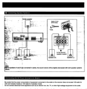
... to the outlet on the receiver does not exceed 120 watts for USA and Canada models or 100 watts for Australian model. 0 Connecting Speaker Systems Center speaker .q% N Approx.15 mm (9/16 inches) L, FRONT RS R A 010•4 0 A ear ew ) speaker (L) to the second speaker system Speaker (R) Speaker (L) rfirthe speakers A and B are connected in series, the sound volume will be slightly decreased with both speaker systems ardven. Connecting the AC Power (Except U.K.
... to the outlet on the receiver does not exceed 120 watts for USA and Canada models or 100 watts for Australian model. 0 Connecting Speaker Systems Center speaker .q% N Approx.15 mm (9/16 inches) L, FRONT RS R A 010•4 0 A ear ew ) speaker (L) to the second speaker system Speaker (R) Speaker (L) rfirthe speakers A and B are connected in series, the sound volume will be slightly decreased with both speaker systems ardven. Connecting the AC Power (Except U.K.
Operating Instructions
Page 8
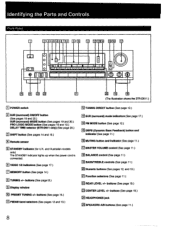
... 19.) 23 CENTER LEVEL +/- buttons (See pagel3.) El Display window M PRESET TUNING +1- and Australian models only) The STANDBY indicator lights up when the power cord is connected. buttons (See page 19.) 24 HEADPHONES jack SPEAKERS NB buttons (See page 11.) 8 Identifying the Parts and Controls Front Panel EICEIDEEI MN 0 BC1E1 CIO CD O O -1O OI uu a ir IL I El E.. 18 (The illustration shows the STR-D611.) El POWER switch ElTUNING DIRECT button (See page 12...
... 19.) 23 CENTER LEVEL +/- buttons (See pagel3.) El Display window M PRESET TUNING +1- and Australian models only) The STANDBY indicator lights up when the power cord is connected. buttons (See page 19.) 24 HEADPHONES jack SPEAKERS NB buttons (See page 11.) 8 Identifying the Parts and Controls Front Panel EICEIDEEI MN 0 BC1E1 CIO CD O O -1O OI uu a ir IL I El E.. 18 (The illustration shows the STR-D611.) El POWER switch ElTUNING DIRECT button (See page 12...
Operating Instructions
Page 9
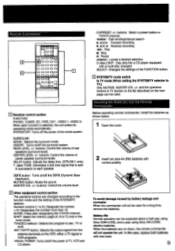
... number. >10: Designates the number more than 10. Remote Commander EJ C3 0 0 075 0 0 CI 0 1313 0 0 CI I= 0 CI CI 0 0 CI 0 0 0 0 0 0 0 0 =I 0 Ej Receiver control section FUNCTION PHONO, TUNER, CD, TAPE, DAT , VIDEO 1, VIDEO 2: When each function is sent in succession to each speaker. ON/OFF: Turns on /off the power of the SYSTEM/TV selector. CENTER LEVEL +/- DELAY button: Adjusts the delay time. (STR-D611 only) T. (test) TONE: Generates a test tone signal that is selected, the unit enters its operating mode automatically. Numeric buttons...
... number. >10: Designates the number more than 10. Remote Commander EJ C3 0 0 075 0 0 CI 0 1313 0 0 CI I= 0 CI CI 0 0 CI 0 0 0 0 0 0 0 0 =I 0 Ej Receiver control section FUNCTION PHONO, TUNER, CD, TAPE, DAT , VIDEO 1, VIDEO 2: When each function is sent in succession to each speaker. ON/OFF: Turns on /off the power of the SYSTEM/TV selector. CENTER LEVEL +/- DELAY button: Adjusts the delay time. (STR-D611 only) T. (test) TONE: Generates a test tone signal that is selected, the unit enters its operating mode automatically. Numeric buttons...
Operating Instructions
Page 10
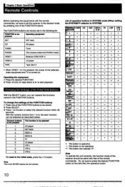
... 4 (only for tape deck) or w• to be pressed Operating equipment DAT DAT deck CD CD player TUNER Tuner PHONO (The receiver enters the PHONO mode.) VIDEO 1 Betamax VCRs (VCR 1) VIDEO 2 LD player TAPE Tape deck A • When VIDEO 1 or 2 is pressed, the power of the selected video equipment and TV is not operative. •*: The button can replace the functions stored in the FUNCTION buttons. FUNCTION to start playback. Note The 0 and ENTER buttons do not function. LDP VTR...
... 4 (only for tape deck) or w• to be pressed Operating equipment DAT DAT deck CD CD player TUNER Tuner PHONO (The receiver enters the PHONO mode.) VIDEO 1 Betamax VCRs (VCR 1) VIDEO 2 LD player TAPE Tape deck A • When VIDEO 1 or 2 is pressed, the power of the selected video equipment and TV is not operative. •*: The button can replace the functions stored in the FUNCTION buttons. FUNCTION to start playback. Note The 0 and ENTER buttons do not function. LDP VTR...
Operating Instructions
Page 11
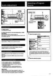
...PHONO .: .. Press again to a low level temporarily (- 20 dB attenuation) Press MUTING and the indicator lights up . TUNER .• - deck 1 Select the progam source. Adjusting Left and Right Sound Balance Adjust BALANCE to on . 2 Start the selected program. -4 -4 Audio Adjustment Selecting a Program Source is O O O O O 0000 r*PPI.KERS, VMOASLUTEMRE MUTING • oe ©I 11-1 BASS and BALANCE TREBLE Adjusting volume To adjust volume Turn MASTER VOLUME. mpact disc CD DAT.or Taped TAPE/DAT _ r9gralna ' VIDEO 1, VIDEO 2/LD If only pressing one of its operating...
...PHONO .: .. Press again to a low level temporarily (- 20 dB attenuation) Press MUTING and the indicator lights up . TUNER .• - deck 1 Select the progam source. Adjusting Left and Right Sound Balance Adjust BALANCE to on . 2 Start the selected program. -4 -4 Audio Adjustment Selecting a Program Source is O O O O O 0000 r*PPI.KERS, VMOASLUTEMRE MUTING • oe ©I 11-1 BASS and BALANCE TREBLE Adjusting volume To adjust volume Turn MASTER VOLUME. mpact disc CD DAT.or Taped TAPE/DAT _ r9gralna ' VIDEO 1, VIDEO 2/LD If only pressing one of its operating...

Operating Instructions
Page 14
... a Station Directly".) 3 Press MEMORY and the MEMORY indicator appears for a few seconds. Replacing a preset station Preset another station on the number of the station to 0), while the MEMORY indicator is maintained for presetting other desired stations. IMPORTANT The memorized station is displayed. Each time the button pressed, A, B or C is disconnected from the AC power outlet. Receiving FM/AM Broadcasts Presetting Stations A total of 30 FM/AM stations can be used to...
... a Station Directly".) 3 Press MEMORY and the MEMORY indicator appears for a few seconds. Replacing a preset station Preset another station on the number of the station to 0), while the MEMORY indicator is maintained for presetting other desired stations. IMPORTANT The memorized station is displayed. Each time the button pressed, A, B or C is disconnected from the AC power outlet. Receiving FM/AM Broadcasts Presetting Stations A total of 30 FM/AM stations can be used to...
Operating Instructions
Page 16
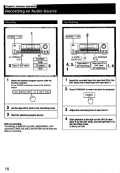
... Tuner CD la r VCR r"'", Select the desired program source with the function selector. TAPE/DAT b 3 Adjust the recording level of tape deck A. 4 Start playback of MASTER VOLUME, BASS/TREBLE, SUR (surround), DBFB, BALANCE and MUTING do not have any effect on recording. Note on recording The settings of the tape (or the DAT) in the desired station. Chpater 3 Advanced Operations Recording an Audio Source Recording Tape Dubbing POWER -•• ON 0 0 0 00 0 0 On to VIDEO 1 n AUDIO...
... Tuner CD la r VCR r"'", Select the desired program source with the function selector. TAPE/DAT b 3 Adjust the recording level of tape deck A. 4 Start playback of MASTER VOLUME, BASS/TREBLE, SUR (surround), DBFB, BALANCE and MUTING do not have any effect on recording. Note on recording The settings of the tape (or the DAT) in the desired station. Chpater 3 Advanced Operations Recording an Audio Source Recording Tape Dubbing POWER -•• ON 0 0 0 00 0 0 On to VIDEO 1 n AUDIO...
Operating Instructions
Page 17
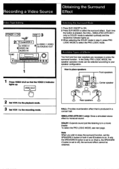
... speakers Front speakers 1 Press VIDEO 2/LD so that the VIDEO 2 indicator lights up . 3 When selecting the DOLBY mode in a concert hall. How to in a movie theater. To select the PRO LOGIC MODE, see next page. In the Dolby PRO LOGIC MODE, the speaker operation mode can be obtained. If only the SPEAKERS B button is set the SPEAKERS A button or both A and B buttons to monaural sound. VIDEO 2/LD ~p t11 Center speaker 2 Set VCR 2 to select the surround effect. Recording a Video Source Obtaining the Surround Effect Video Tape...
... speakers Front speakers 1 Press VIDEO 2/LD so that the VIDEO 2 indicator lights up . 3 When selecting the DOLBY mode in a concert hall. How to in a movie theater. To select the PRO LOGIC MODE, see next page. In the Dolby PRO LOGIC MODE, the speaker operation mode can be obtained. If only the SPEAKERS B button is set the SPEAKERS A button or both A and B buttons to monaural sound. VIDEO 2/LD ~p t11 Center speaker 2 Set VCR 2 to select the surround effect. Recording a Video Source Obtaining the Surround Effect Video Tape...
Operating Instructions
Page 18
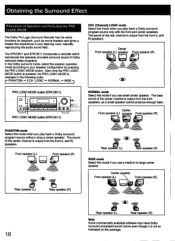
...mode Select this mode when you use a medium to your listening room, naturally reproducing the audio sound field. Center Front speaker (L) speaker Front speaker (R) Qgcr3 PRO LOGIC MODE button (STR-D611) 0 o 0 00 • • • .1.-1-1 • • oO • ,, O 10:0 PRO LOGIC MODE button (STR-D511) PHANTOM mode Select this mode if you play back a Dolby surround program source only with the front and center speakers. The bass sound of the center channel is output from the front (L and R) speakers. The sound of the center channel is r .changed in your speaker...
...mode Select this mode when you use a medium to your listening room, naturally reproducing the audio sound field. Center Front speaker (L) speaker Front speaker (R) Qgcr3 PRO LOGIC MODE button (STR-D611) 0 o 0 00 • • • .1.-1-1 • • oO • ,, O 10:0 PRO LOGIC MODE button (STR-D511) PHANTOM mode Select this mode if you play back a Dolby surround program source only with the front and center speakers. The bass sound of the center channel is output from the front (L and R) speakers. The sound of the center channel is r .changed in your speaker...

Operating Instructions
Page 19
.... TONE on the remote commander to set to adjust the level of center speaker so that sound from the front L, center, front R, and the rear speakers in the same volume level at the listening position. (When adjusting the VOLUME control on the receiver, all surround modes. Adjusting the Speaker Volume To enjoy the surround sound to the maximum on playing any program sources, adjust the front, rear, and center (if connected ) speakers to your listening position by using the remote commander. Sequence of rear and center speakers...
.... TONE on the remote commander to set to adjust the level of center speaker so that sound from the front L, center, front R, and the rear speakers in the same volume level at the listening position. (When adjusting the VOLUME control on the receiver, all surround modes. Adjusting the Speaker Volume To enjoy the surround sound to the maximum on playing any program sources, adjust the front, rear, and center (if connected ) speakers to your listening position by using the remote commander. Sequence of rear and center speakers...
Operating Instructions
Page 20
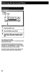
... Delay Time of the surround is resumed. and CENTER LEVEL +/- They will resume. :ear level, center level and delay time of the Rear Speakers STR-D611 only) POWER ON 12 0 00 0 00 0 0 0 0 0 0 0 1 Press SUR ON/OFF to ON. 2 Press SUR MODE to select DOLBY. 3 Press DELAY TIME on the front panel or DELAY on the remote commander to get an optimum rear Nei as long as each time after adjusting with the DELAY TIME, lEAR LEVEL +/- buttons. o turn off the surround...
... Delay Time of the surround is resumed. and CENTER LEVEL +/- They will resume. :ear level, center level and delay time of the Rear Speakers STR-D611 only) POWER ON 12 0 00 0 00 0 0 0 0 0 0 0 1 Press SUR ON/OFF to ON. 2 Press SUR MODE to select DOLBY. 3 Press DELAY TIME on the front panel or DELAY on the remote commander to get an optimum rear Nei as long as each time after adjusting with the DELAY TIME, lEAR LEVEL +/- buttons. o turn off the surround...
Operating Instructions
Page 21
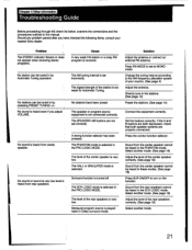
... 4) Adjust the antenna. Change the tuning interval according to MONO mode. A wrong function selector has been pressed. Surround function is very low. Press the correct function selector. Press FM MODE to set to the AM frequency allocation system of the center speaker is turned off. The level of your nearest Sony dealer. The AM tuning interval is played back in the PRO LOGIC MODE. The SPEAKERS NB buttons are properly connected. Monaural program source is set correctly. Select another mode...
... 4) Adjust the antenna. Change the tuning interval according to MONO mode. A wrong function selector has been pressed. Surround function is very low. Press the correct function selector. Press FM MODE to set to the AM frequency allocation system of the center speaker is turned off. The level of your nearest Sony dealer. The AM tuning interval is played back in the PRO LOGIC MODE. The SPEAKERS NB buttons are properly connected. Monaural program source is set correctly. Select another mode...
Operating Instructions
Page 22
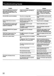
... plugs and jacks with a cloth lightly dampened with new ones. Surround circuit is not pointed toward the receiver. 22 The batteries are too close to set appropriately. Cause A short-circuit problem activates the protective circuit. Connect the ground wire to disengage. Troubleshooting Guide Problem There is an abrupt loss of sound from one or both are used at the same time, separate the TV from the audio components...
... plugs and jacks with a cloth lightly dampened with new ones. Surround circuit is not pointed toward the receiver. 22 The batteries are too close to set appropriately. Cause A short-circuit problem activates the protective circuit. Connect the ground wire to disengage. Troubleshooting Guide Problem There is an abrupt loss of sound from one or both are used at the same time, separate the TV from the audio components...
Operating Instructions
Page 23
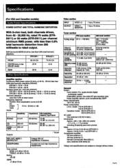
... quartz-locked digital synthesizer system Preamplifier section: low-noise NF type equalizer amp Power amplifier section: pure complementary SEPP Power requirements 120 V AC, 60 Hz Power consumption U.S.A. Specifications (For USA and Canadian models) Audio Power Specifications POWER OUTPUT AND TOTAL HARMONIC DISTORTION With 8-ohm load, both channels driven, from 250 milliwatts to rated output. Usable sensitivity 11.2 dBf, 2 µV (IHF) Loop antenna: 500 µV (at 1,000 kHz) Signal-to change without...
... quartz-locked digital synthesizer system Preamplifier section: low-noise NF type equalizer amp Power amplifier section: pure complementary SEPP Power requirements 120 V AC, 60 Hz Power consumption U.S.A. Specifications (For USA and Canadian models) Audio Power Specifications POWER OUTPUT AND TOTAL HARMONIC DISTORTION With 8-ohm load, both channels driven, from 250 milliwatts to rated output. Usable sensitivity 11.2 dBf, 2 µV (IHF) Loop antenna: 500 µV (at 1,000 kHz) Signal-to change without...
Operating Instructions
Page 24
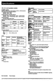
... Hz) 30 dB at rated output SUR (surround ) MODE (8 ohms, less than 0.8% total harmonic distortion STR-D611 STR-D511 FRONT 60W +60W 50 W +50 W CENTER (only in Malaysia Video section *Tr VIDEO1,2 tUTPUT i VIDEO 1 _ _. _ MONITOR 1Vp-p 75 ohms 1Vp-p 75 ohms Tuner section ,--- 7-_--- Specifications (For U.K. ril*--P-anse .osdB -2 General System Tuner section: PLL quartz-locked digital synthesizer system Preamplifier section: low-noise NF type equalizer amp Power amplifier section: pure complementary SEPP...
... Hz) 30 dB at rated output SUR (surround ) MODE (8 ohms, less than 0.8% total harmonic distortion STR-D611 STR-D511 FRONT 60W +60W 50 W +50 W CENTER (only in Malaysia Video section *Tr VIDEO1,2 tUTPUT i VIDEO 1 _ _. _ MONITOR 1Vp-p 75 ohms 1Vp-p 75 ohms Tuner section ,--- 7-_--- Specifications (For U.K. ril*--P-anse .osdB -2 General System Tuner section: PLL quartz-locked digital synthesizer system Preamplifier section: low-noise NF type equalizer amp Power amplifier section: pure complementary SEPP...


