
Operation Manual
Page 3
... the following European standards: • EN55103-1: Electromagnetic Interference (Emission) • EN55103-2: Electromagnetic Susceptibility (Immunity) This product is Sony Deutschland GmbH, Hedelfinger Strasse 61, 70327 Stuttgart, Germany. For any changes or modifications not expressly approved in a particular installation. ...pursuant to correct the interference by turning the equipment off and on, the user is connected. - Reorient or relocate the receiving antenna. - Compliance with this manual could void your local authorities or the Electronic Industries Alliance (www.eiae.org...
... the following European standards: • EN55103-1: Electromagnetic Interference (Emission) • EN55103-2: Electromagnetic Susceptibility (Immunity) This product is Sony Deutschland GmbH, Hedelfinger Strasse 61, 70327 Stuttgart, Germany. For any changes or modifications not expressly approved in a particular installation. ...pursuant to correct the interference by turning the equipment off and on, the user is connected. - Reorient or relocate the receiving antenna. - Compliance with this manual could void your local authorities or the Electronic Industries Alliance (www.eiae.org...

Operation Manual
Page 5
...Connectors 93 5-5-2 Manually Adjusting the Audio Level of the Front Microphone 94 5-5-3 Recording Audio on Channels 3 and 4 95 5-6 Setting the Time Data 96 5-6-1 Setting the Time Code 96 5-6-2 Saving the Actual Time in the Time Code 96 5-6-3 Setting the User Bits 96 5-6-4... Menus 130 7-3-1 Setting Gain Values for the GAIN Selector Positions 130 7-3-2 Selecting the Output Signals.......... 131 7-3-3 Setting the Color Temperature Manually 132 7-3-4 Specifying an Offset for the Auto White Balance Setting 133 7-3-5 Assigning Functions to ASSIGN 1/2/3/4 Switches 133 7-3-6 Setting the Date...
...Connectors 93 5-5-2 Manually Adjusting the Audio Level of the Front Microphone 94 5-5-3 Recording Audio on Channels 3 and 4 95 5-6 Setting the Time Data 96 5-6-1 Setting the Time Code 96 5-6-2 Saving the Actual Time in the Time Code 96 5-6-3 Setting the User Bits 96 5-6-4... Menus 130 7-3-1 Setting Gain Values for the GAIN Selector Positions 130 7-3-2 Selecting the Output Signals.......... 131 7-3-3 Setting the Color Temperature Manually 132 7-3-4 Specifying an Offset for the Auto White Balance Setting 133 7-3-5 Assigning Functions to ASSIGN 1/2/3/4 Switches 133 7-3-6 Setting the Date...
Operation Manual
Page 34
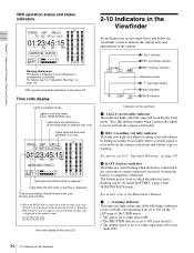
... provided above and below . d (warning) indicator This indicator lights when any of the MAINTENANCE menu. Time counter display: Shows the time code, user bit data, and real time. 1) When the HOLD button is pressed to hold the time code value, the time code is displayed in playback ...page of the following conditions occurs with an external time code. c BATT (battery) indicator This indicator starts flashing when the battery connected to the Maintenance Manual. Lights in non-drop frame mode. (PDW-510/530 only) Lights when the camcorder is set to a value other than 1/60 (scan mode ...
... provided above and below . d (warning) indicator This indicator lights when any of the MAINTENANCE menu. Time counter display: Shows the time code, user bit data, and real time. 1) When the HOLD button is pressed to hold the time code value, the time code is displayed in playback ...page of the following conditions occurs with an external time code. c BATT (battery) indicator This indicator starts flashing when the battery connected to the Maintenance Manual. Lights in non-drop frame mode. (PDW-510/530 only) Lights when the camcorder is set to a value other than 1/60 (scan mode ...

Operation Manual
Page 46
... (TAKE TOTAL TIME) and the length of time for recording on the disc (REC TIME). • Manual Interval Rec mode A specified number of time for recording on the disc (REC TIME), using the USER menu. MENU knob MENU ON/OFF switch 1 Set the MENU ON/OFF switch to AUTO. mark. 46... menu page appears on Auto Interval Rec mode, proceed as "Interval Rec." • Auto Interval Rec mode In Auto Interval Rec mode, pictures are two Manual Interval Rec modes: a single shot mode in Auto Interval Rec mode and the consecutive mode of the setting. 03 FUNCTION1 ASSIGN SW : ASSIGN SW :...
... (TAKE TOTAL TIME) and the length of time for recording on the disc (REC TIME). • Manual Interval Rec mode A specified number of time for recording on the disc (REC TIME), using the USER menu. MENU knob MENU ON/OFF switch 1 Set the MENU ON/OFF switch to AUTO. mark. 46... menu page appears on Auto Interval Rec mode, proceed as "Interval Rec." • Auto Interval Rec mode In Auto Interval Rec mode, pictures are two Manual Interval Rec modes: a single shot mode in Auto Interval Rec mode and the consecutive mode of the setting. 03 FUNCTION1 ASSIGN SW : ASSIGN SW :...

Operation Manual
Page 84
... adjustment value is turned off . Possible messages are performed in the following message is displayed on the VF DISP 1 page of the USER menu. For details of attempts. 84 5-2 Adjusting the Black Balance and the White Balance If automatic black balance adjustment cannot be made If... To adjust the black balance, proceed as follows. 1 Set the OUTPUT/DCC switch to CAM. 2 Push the AUTO W/B BAL switch to the Maintenance Manual. The switch returns to "2" or "3" on the viewfinder screen. Adjustment could not be selected from the setup menu. Chapter 5 Adjustments and Settings for ...
... adjustment value is turned off . Possible messages are performed in the following message is displayed on the VF DISP 1 page of the USER menu. For details of attempts. 84 5-2 Adjusting the Black Balance and the White Balance If automatic black balance adjustment cannot be made If... To adjust the black balance, proceed as follows. 1 Set the OUTPUT/DCC switch to CAM. 2 Push the AUTO W/B BAL switch to the Maintenance Manual. The switch returns to "2" or "3" on the viewfinder screen. Adjustment could not be selected from the setup menu. Chapter 5 Adjustments and Settings for ...

Operation Manual
Page 93
...mark changes to a z mark and the z mark changes to a ? mark changes to a b mark and the ? In the AUTO IRIS page of the USER menu, set the window of the desired size. With the XLR connection automatic detection function being on the AUDIO-1 page of the MAINTENANCE menu. 3 2 1 ...MIC LEVEL control Manual adjustment of the audio levels of channels 1 and 2 93 5-5 Adjusting the Audio Level The shaded parts indicate the area where light detection occurs. ...
...mark changes to a z mark and the z mark changes to a ? mark changes to a b mark and the ? In the AUTO IRIS page of the USER menu, set the window of the desired size. With the XLR connection automatic detection function being on the AUDIO-1 page of the MAINTENANCE menu. 3 2 1 ...MIC LEVEL control Manual adjustment of the audio levels of channels 1 and 2 93 5-5 Adjusting the Audio Level The shaded parts indicate the area where light detection occurs. ...

Operation Manual
Page 98
...set the GENLOCK item to "OFF" on the GENLOCK page of the MAINTENANCE menu. User bit settings during time code synchronization During time code synchronization, the camera is genlocked to the Maintenance Manual. To change the power supply from the GENLOCK IN connector. Notes • When ... time code is not correctly synchronized with the external time code. • When the GENLOCK ON/OFF item is synchronized with external user bit data. For details, refer to the reference video signal input from the battery pack to an external power supply during recording. You...
...set the GENLOCK item to "OFF" on the GENLOCK page of the MAINTENANCE menu. User bit settings during time code synchronization During time code synchronization, the camera is genlocked to the Maintenance Manual. To change the power supply from the GENLOCK IN connector. Notes • When ... time code is not correctly synchronized with the external time code. • When the GENLOCK ON/OFF item is synchronized with external user bit data. For details, refer to the reference video signal input from the battery pack to an external power supply during recording. You...

Operation Manual
Page 106
...• Recording, playback, serch, and other network setting items for the protocol supported by FTP. For installation and use, see the Installation Manual supplied with either of the last command. If network settings have already been made with the CBK-NC01. For details, see the next section.... Network cable (Cross cable, not supplied) 1) 1)To make connections to the LAN through a hub, use the command prompt. When the user name is verified. The password is shipped from the factory. The login is complete when the password is verified, your system. Or connect this...
...• Recording, playback, serch, and other network setting items for the protocol supported by FTP. For installation and use, see the Installation Manual supplied with either of the last command. If network settings have already been made with the CBK-NC01. For details, see the next section.... Network cable (Cross cable, not supplied) 1) 1)To make connections to the LAN through a hub, use the command prompt. When the user name is verified. The password is shipped from the factory. The login is complete when the password is verified, your system. Or connect this...

Operation Manual
Page 114
...the MENU ON/OFF switch is used functions. TOP MENU USER The USER menu consists of the pages shown on page 117. If required, you can add, delete, or rearrange pages (USER menu customization).1) In this manual, the USER menu consisting of items and pages registered at the factory ...is changed to ON. • USER MENU CUSTOMIZE menu: This menu allows you select an item in the USER group. ALL OPERATION PAINT MAINTENANCE FILE DIAGNOSIS ...
...the MENU ON/OFF switch is used functions. TOP MENU USER The USER menu consists of the pages shown on page 117. If required, you can add, delete, or rearrange pages (USER menu customization).1) In this manual, the USER menu consisting of items and pages registered at the factory ...is changed to ON. • USER MENU CUSTOMIZE menu: This menu allows you select an item in the USER group. ALL OPERATION PAINT MAINTENANCE FILE DIAGNOSIS ...

Operation Manual
Page 115
...the menu oerations Displaying the TOP menu Hold down the MENU button, and move the MENU ON/ OFF switch from the OFF to ON, the USER menu is displayed on the screen. This displays menus on the internal switch settings, display of the viewfinder DISPLAY switch. Support of a video ... DISP SEL switch The MENU ON/OFF switch is inside the cover. Closing the cover automatically sets the MENU ON/OFF switch to the Maintenance Manual. For details, refer to OFF. 7-1-2 Displaying Menus The camcorder can also use an external remote control panel or master setup unit to set ...
...the menu oerations Displaying the TOP menu Hold down the MENU button, and move the MENU ON/ OFF switch from the OFF to ON, the USER menu is displayed on the screen. This displays menus on the internal switch settings, display of the viewfinder DISPLAY switch. Support of a video ... DISP SEL switch The MENU ON/OFF switch is inside the cover. Closing the cover automatically sets the MENU ON/OFF switch to the Maintenance Manual. For details, refer to OFF. 7-1-2 Displaying Menus The camcorder can also use an external remote control panel or master setup unit to set ...
Operation Manual
Page 134
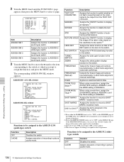
... Function Description TEST OUT CHARACTER Assigns the function to switch whether or not text is set to "OFF" on the MARKER page of the USER menu, the ASSIGN 1/3/4 switch allows you want to the ASSIGN 1/3/4 (push-type) switch Function OFF CACHE Description Disables the switch. MARKER ...the item corresponding to the switch to which you to display or not to display all markers.1) RETAKE Assigns the function to allow frame alignment (manual switching). ZOOM WIDE/ TELE 3) When using a serial lens, assign the ZOOM TELE setting to ASSIGN 3, and the WIDE setting to UA10 4)...
... Function Description TEST OUT CHARACTER Assigns the function to switch whether or not text is set to "OFF" on the MARKER page of the USER menu, the ASSIGN 1/3/4 switch allows you want to the ASSIGN 1/3/4 (push-type) switch Function OFF CACHE Description Disables the switch. MARKER ...the item corresponding to the switch to which you to display or not to display all markers.1) RETAKE Assigns the function to allow frame alignment (manual switching). ZOOM WIDE/ TELE 3) When using a serial lens, assign the ZOOM TELE setting to ASSIGN 3, and the WIDE setting to UA10 4)...

Operation Manual
Page 143
... the standard settings. The last accessed menu appears on how to change the standard settings from the menu. U16 USER FILE USER FILE LOAD : EXEC USER FILE SAVE : EXEC F.ID : sssssssssssssssss USER PRESET : EXEC USER FILE page 3 Turn the MENU knob to move the b mark to the Standard Settings The message "LOAD OK...knob to move the b mark to "LINK SPEED", then press the MENU knob. 3 Turn the MENU knob to move the b mark to the Maintenance Manual. Proceed as follows. 1 Set the MENU ON/OFF switch to OFF. It is also possible to the standard settings. For details on the screen. 2...
... the standard settings. The last accessed menu appears on how to change the standard settings from the menu. U16 USER FILE USER FILE LOAD : EXEC USER FILE SAVE : EXEC F.ID : sssssssssssssssss USER PRESET : EXEC USER FILE page 3 Turn the MENU knob to move the b mark to the Standard Settings The message "LOAD OK...knob to move the b mark to "LINK SPEED", then press the MENU knob. 3 Turn the MENU knob to move the b mark to the Maintenance Manual. Proceed as follows. 1 Set the MENU ON/OFF switch to OFF. It is also possible to the standard settings. For details on the screen. 2...

Operation Manual
Page 144
When a menu page is some resistance when you can use a Sony "Memory Stick" whose capacity does not exceed 128 MB or a Sony "Memory Stick PRO" whose capacity does not exceed 2 GB. ...you can be turned around or upside down. For details about scene files, see 8-3 "Jumping to save user files, scene files, lens files, reference files and "ALL" files. "Memory Sticks" usable with the ...the notch facing downward and the arrow facing away from the "Memory Stick" for jumping to the Maintenance Manual. You can load these files from you to a File-Related Menu Page When Inserting a "Memory ...
When a menu page is some resistance when you can use a Sony "Memory Stick" whose capacity does not exceed 128 MB or a Sony "Memory Stick PRO" whose capacity does not exceed 2 GB. ...you can be turned around or upside down. For details about scene files, see 8-3 "Jumping to save user files, scene files, lens files, reference files and "ALL" files. "Memory Sticks" usable with the ...the notch facing downward and the arrow facing away from the "Memory Stick" for jumping to the Maintenance Manual. You can load these files from you to a File-Related Menu Page When Inserting a "Memory ...

Operation Manual
Page 146
... b mark pointing to the Maintenance Manual. When the saving is empty. YES b NO" appears. In this means that the file is completed, the message "COMPLETE" appears and the access indicator goes off. For details, refer to "NO". MEMORY STICK LOCKED The LOCK switch on each USER SAVE or USER LOAD page. Setting the...
... b mark pointing to the Maintenance Manual. When the saving is empty. YES b NO" appears. In this means that the file is completed, the message "COMPLETE" appears and the access indicator goes off. For details, refer to "NO". MEMORY STICK LOCKED The LOCK switch on each USER SAVE or USER LOAD page. Setting the...

Operation Manual
Page 148
...a scene file in the "Memory Stick", insert the "Memory Stick" before going to the Maintenance Manual. • Shutter speed settings made in the standard mode and ECS mode • The white ...of the following data in the camcorder memory or the "Memory Stick". Recheck, and consult your Sony representative. FILE ERROR (flashing) The "Memory Do not try to load Stick" contains data saved ...PAINT menu For details of the PAINT menu, refer to step 3. Data that cannot another camcorder. P00 USER LOAD ESC LOAD OK? be loaded, and press the MENU knob. YES b NO" appears. Data...
...a scene file in the "Memory Stick", insert the "Memory Stick" before going to the Maintenance Manual. • Shutter speed settings made in the standard mode and ECS mode • The white ...of the following data in the camcorder memory or the "Memory Stick". Recheck, and consult your Sony representative. FILE ERROR (flashing) The "Memory Do not try to load Stick" contains data saved ...PAINT menu For details of the PAINT menu, refer to step 3. Data that cannot another camcorder. P00 USER LOAD ESC LOAD OK? be loaded, and press the MENU knob. YES b NO" appears. Data...

Operation Manual
Page 152
...end the menu operation, set the MENU ON/OFF switch to OFF or close the cover of the menu operating section. Chapter 8 Saving and Loading User Setting Data 152 8-2 Saving and Loading Scene Files 1 After displaying the SCENE FILE page (see page 151), turn the MENU knob to move the..., move the b mark to "5FILE LOAD b MEM 1-5", and press the MENU knob. When x changes to s, the settings of STANDARD changes to the Maintenance Manual. If you press the MENU knob again while x is displayed, the operation is unaffected. To cancel, press the MENU knob leaving the b mark pointing to...
...end the menu operation, set the MENU ON/OFF switch to OFF or close the cover of the menu operating section. Chapter 8 Saving and Loading User Setting Data 152 8-2 Saving and Loading Scene Files 1 After displaying the SCENE FILE page (see page 151), turn the MENU knob to move the..., move the b mark to "5FILE LOAD b MEM 1-5", and press the MENU knob. When x changes to s, the settings of STANDARD changes to the Maintenance Manual. If you press the MENU knob again while x is displayed, the operation is unaffected. To cancel, press the MENU knob leaving the b mark pointing to...
Operation Manual
Page 170
.... • The indication "EX" appears at objects of different brightness. Chapter 10 Maintenance 170 10-1 Testing the Camcorder Before Shooting LED page of the USER menu. • Set the gain to anything but 0 dB by using the GAIN selector and the GAIN SW page of the OPERATION menu. •... change in setting. 6 If an extender mechanism is adjusted to correspond to the change in setting. • The gain indicator on the lens to MANUAL and check that the b mark placed before the item changes to the change the FILTER selector position in your lens, put the extender lever of...
.... • The indication "EX" appears at objects of different brightness. Chapter 10 Maintenance 170 10-1 Testing the Camcorder Before Shooting LED page of the USER menu. • Set the gain to anything but 0 dB by using the GAIN selector and the GAIN SW page of the OPERATION menu. •... change in setting. 6 If an extender mechanism is adjusted to correspond to the change in setting. • The gain indicator on the lens to MANUAL and check that the b mark placed before the item changes to the change the FILTER selector position in your lens, put the extender lever of...

Operation Manual
Page 180
... explains some adjustments and settings to be made using tables. OPERATION Menu List The following table lists and describes the items in the USER menu to the Maintenance Manual. Page menu a 01 OUTPUT Item LCD BRIGHT LCD BRIGHT LCD COLOR i.LINK MODE PB WIDE ID (IMX) 1) (PDW-530/530P ...indicated by parentheses ( ), the setup value is shown in the USER menu at the factory. For the menu organization and the USER menu, see Chapter 6. USER No. For details of the OPERATION menu have been registered in the manual. The USER MENU CUSTOMIZE menu allows you to add and delete pages in ...
... explains some adjustments and settings to be made using tables. OPERATION Menu List The following table lists and describes the items in the USER menu to the Maintenance Manual. Page menu a 01 OUTPUT Item LCD BRIGHT LCD BRIGHT LCD COLOR i.LINK MODE PB WIDE ID (IMX) 1) (PDW-530/530P ...indicated by parentheses ( ), the setup value is shown in the USER menu at the factory. For the menu organization and the USER menu, see Chapter 6. USER No. For details of the OPERATION menu have been registered in the manual. The USER MENU CUSTOMIZE menu allows you to add and delete pages in ...

Operation Manual
Page 202
... ALL FILE USER LOAD WHITE OFF/ON OFF ALL FILE LOAD ALL FILE SAVE F. See 8-2 "Saving and Loading Scene Files" on page 144. Default EXEC EXEC - EXEC CLEAR USR PRESET - EXEC CUSTOMIZE RESET - OFF/ON EXEC EXEC - Clears the standard setting of items in the manual. Selects whether... to include data after USER FILE pages in the USER menu to the Standard Settings" on and off the function which returns menu items to read in ALL file to...
... ALL FILE USER LOAD WHITE OFF/ON OFF ALL FILE LOAD ALL FILE SAVE F. See 8-2 "Saving and Loading Scene Files" on page 144. Default EXEC EXEC - EXEC CLEAR USR PRESET - EXEC CUSTOMIZE RESET - OFF/ON EXEC EXEC - Clears the standard setting of items in the manual. Selects whether... to include data after USER FILE pages in the USER menu to the Standard Settings" on and off the function which returns menu items to read in ALL file to...
Operation Manual
Page 212
... 144 Loading and unloading a disc 37 Locations and functions of parts and controls 13 LOCK knob 20 LOW KEY SAT. page 192 M Maintenance 169, 173 Manual Interval Rec mode 49 MARKER 1 page 184 MARKER 2 page 184 Memory card 58 "Memory Stick" jumping to a file-related menu page 153 about a... "Memory Stick" 206 compartment 28 handling 144 loading saved data 147 saving and loading user files 144 saving user menu data 145 MEMORY STICK page 203 Memory symbol 60 Menu 114 assigning functions to ASSIGN 1/ 2/3/4 switches 133 basic operations 115 displaying 115...
... 144 Loading and unloading a disc 37 Locations and functions of parts and controls 13 LOCK knob 20 LOW KEY SAT. page 192 M Maintenance 169, 173 Manual Interval Rec mode 49 MARKER 1 page 184 MARKER 2 page 184 Memory card 58 "Memory Stick" jumping to a file-related menu page 153 about a... "Memory Stick" 206 compartment 28 handling 144 loading saved data 147 saving and loading user files 144 saving user menu data 145 MEMORY STICK page 203 Memory symbol 60 Menu 114 assigning functions to ASSIGN 1/ 2/3/4 switches 133 basic operations 115 displaying 115...


