
Computer User Guide
Page 14
...of the cable into this port. 2 Plug the other . The total power supplied by calling 1-888-315-7669 (toll free). Sony computer supplies, accessories, and peripherals can : ❑ supply power from your computer. Connecting an i.LINK (IEEE1394) device 1 Use the symbol to 12V. ...All products with an i.LINK connection may vary, depending on your local retailer or by accessing the Sony VAIO Direct Web site (http://vaio...
...of the cable into this port. 2 Plug the other . The total power supplied by calling 1-888-315-7669 (toll free). Sony computer supplies, accessories, and peripherals can : ❑ supply power from your computer. Connecting an i.LINK (IEEE1394) device 1 Use the symbol to 12V. ...All products with an i.LINK connection may vary, depending on your local retailer or by accessing the Sony VAIO Direct Web site (http://vaio...
Quick Start Guide
Page 29
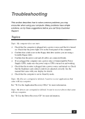
...that the monitor is not in Stand by mode. Check that the power light is lit on the front panel of the computer. ❑ Confirm that a disk is plugged into a power strip or Uninterruptible Power Supply (UPS), make sure the power strip or UPS is turned on and working. ❑ Check ...Use the Application Recovery CD(s)" for more information. Topic: My drivers are corrupted or deleted. I want to recover drivers that the computer is turned on . Troubleshooting This section describes how to solve common problems you call Sony Customer Support. See the manual that came with your...
...that the monitor is not in Stand by mode. Check that the power light is lit on the front panel of the computer. ❑ Confirm that a disk is plugged into a power strip or Uninterruptible Power Supply (UPS), make sure the power strip or UPS is turned on and working. ❑ Check ...Use the Application Recovery CD(s)" for more information. Topic: My drivers are corrupted or deleted. I want to recover drivers that the computer is turned on . Troubleshooting This section describes how to solve common problems you call Sony Customer Support. See the manual that came with your...
Quick Start Guide
Page 40
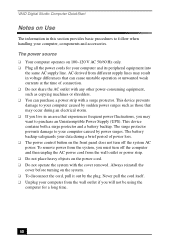
... to purchase an Uninterruptible Power Supply (UPS). Always reinstall the cover before turning on the power cord. ❑ Do not operate the system with the cover removed. VAIO Digital Studio Computer QuickStart Notes on Use The information in this section provides basic procedures to your computer caused by power surges. The power source ❑ Your computer operates on 100...
... to purchase an Uninterruptible Power Supply (UPS). Always reinstall the cover before turning on the power cord. ❑ Do not operate the system with the cover removed. VAIO Digital Studio Computer QuickStart Notes on Use The information in this section provides basic procedures to your computer caused by power surges. The power source ❑ Your computer operates on 100...

Quick Start Guide
Page 41
Notes on loose surfaces (such as rugs or blankets) or near your Sony computer in a location subject to: ❑ Heat sources, such as curtains or draperies) that may block its ventilation slots. In some areas, the disposal of the power supply to qualified personnel only. The lithium battery may cause a malfunction. ❑ Provide adequate air...
Notes on loose surfaces (such as rugs or blankets) or near your Sony computer in a location subject to: ❑ Heat sources, such as curtains or draperies) that may block its ventilation slots. In some areas, the disposal of the power supply to qualified personnel only. The lithium battery may cause a malfunction. ❑ Provide adequate air...

Quick Start Guide
Page 52
... VAIO Action Setup 27 VisualFlow 27 WordPerfect 27 SonicStage 26 Sony on Yahoo! 27 SonyStyle Connect 27 Stand by mode 19 surge protection 40 System Hibernate mode 20 System response problems 38 system upgrading 43 T Troubleshooting Change parallel port type 31 computer ...Recover drivers 29 Software problems 33, 34 starting the computer 29 System response 38 turning off computer 21 turning on computer 16 U Uninterruptible Power Supply 40 upgrading procedures 43 UPS 40 Utilities driver recovery 29 V VAIO AV Applications 5 VAIO Smart keyboard 6 ventilation 10 Viewing angle display 10 VisualFlow...
... VAIO Action Setup 27 VisualFlow 27 WordPerfect 27 SonicStage 26 Sony on Yahoo! 27 SonyStyle Connect 27 Stand by mode 19 surge protection 40 System Hibernate mode 20 System response problems 38 system upgrading 43 T Troubleshooting Change parallel port type 31 computer ...Recover drivers 29 Software problems 33, 34 starting the computer 29 System response 38 turning off computer 21 turning on computer 16 U Uninterruptible Power Supply 40 upgrading procedures 43 UPS 40 Utilities driver recovery 29 V VAIO AV Applications 5 VAIO Smart keyboard 6 ventilation 10 Viewing angle display 10 VisualFlow...
System Reference Manual
Page 10
...38 Installing a 3.5-inch Internal Hard Disk Drive 39 To identify additional hard disk space 43 Removing the Power Supply 44 Replacing the Power Supply 45 Chapter 4 - CMOS Setup Options 53 Main Screen 55 Advanced Screen 57 Power Screen 59 Boot Screen 60 Exit Screen 61 Chapter 6 - Removing, Installing, and Replacing Components 23... 37 Covering an Open I /O Address Map 69 Memory Map 71 IRQ Settings 72 System Board 47 Memory Module (DIMM) Slots 48 Power Supply and Aux Power Headers 49 CLR CMOS Jumper 51 Chapter 5 - x VAIO Digital Studio System Reference Manual Chapter 3 -
...38 Installing a 3.5-inch Internal Hard Disk Drive 39 To identify additional hard disk space 43 Removing the Power Supply 44 Replacing the Power Supply 45 Chapter 4 - CMOS Setup Options 53 Main Screen 55 Advanced Screen 57 Power Screen 59 Boot Screen 60 Exit Screen 61 Chapter 6 - Removing, Installing, and Replacing Components 23... 37 Covering an Open I /O Address Map 69 Memory Map 71 IRQ Settings 72 System Board 47 Memory Module (DIMM) Slots 48 Power Supply and Aux Power Headers 49 CLR CMOS Jumper 51 Chapter 5 - x VAIO Digital Studio System Reference Manual Chapter 3 -

System Reference Manual
Page 33
For more information about configuring a UPS device, refer to select and configure an Uninterruptible Power Supply (UPS) device for your system. 9 Select and configure the settings most appropriate for your Microsoft® Windows® XP operating system online Help. The UPS tab enables you to your system and click OK. Configuring Your System 21 8 Click the UPS tab.
For more information about configuring a UPS device, refer to select and configure an Uninterruptible Power Supply (UPS) device for your system. 9 Select and configure the settings most appropriate for your Microsoft® Windows® XP operating system online Help. The UPS tab enables you to your system and click OK. Configuring Your System 21 8 Click the UPS tab.

System Reference Manual
Page 36
Pull out tab to access the system board, add-in cards, power supply, battery, memory, and internal drives. 1 From the rear of the unit, pull the metal tab shown in the next diagram. 2 Pull the top of the cover away from the unit about two inches, then gently lift out the cover. 24 VAIO Digital Studio System Reference Manual Removing the Side Cover You must remove the side cover to release front panel Pull out top a few inches, then lift out
Pull out tab to access the system board, add-in cards, power supply, battery, memory, and internal drives. 1 From the rear of the unit, pull the metal tab shown in the next diagram. 2 Pull the top of the cover away from the unit about two inches, then gently lift out the cover. 24 VAIO Digital Studio System Reference Manual Removing the Side Cover You must remove the side cover to release front panel Pull out top a few inches, then lift out
System Reference Manual
Page 39
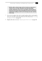
As a precaution, touch any exposed metal part on the metal chassis (preferably the metal part on the power supply) before handling an add-in card to discharge any components or contacts on the card. Hold the add-in card by its edges and do ...
As a precaution, touch any exposed metal part on the metal chassis (preferably the metal part on the power supply) before handling an add-in card to discharge any components or contacts on the card. Hold the add-in card by its edges and do ...
System Reference Manual
Page 45
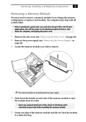
... the memory module to remove. ✍ The memory modules are located beneath the power supply. 4 Push down the computer, and unplug the power cord. 1 Remove the side cover (see "Removing the Side Cover" on page 24). 2 Remove the power supply (see "Removing the Power Supply" on each side of the memory module and lift out. Before opening the...
... the memory module to remove. ✍ The memory modules are located beneath the power supply. 4 Push down the computer, and unplug the power cord. 1 Remove the side cover (see "Removing the Side Cover" on page 24). 2 Remove the power supply (see "Removing the Power Supply" on each side of the memory module and lift out. Before opening the...
System Reference Manual
Page 46
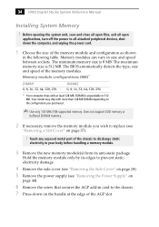
... staticelectricity damage. 4 Remove the side cover (see "Removing the Side Cover" on page 24). 5 Remove the power supply (see "Removing a Slot Cover" on page 37). ! 34 VAIO Digital Studio System Reference Manual Installing System Memory ! Does not support EDO memory or buffered SDRAM memory. 2 If necessary... 64, 128, 256 DIMM2 0, 8, 16, 32, 64, 128, 256 * Your computer ships with more than 128 MB SDRAM depending on the configuration you wish to the chassis. 7 Press down the computer, and unplug the power cord. 1 Choose the size of the AGP slot. Before opening the system unit, save...
... staticelectricity damage. 4 Remove the side cover (see "Removing the Side Cover" on page 24). 5 Remove the power supply (see "Removing a Slot Cover" on page 37). ! 34 VAIO Digital Studio System Reference Manual Installing System Memory ! Does not support EDO memory or buffered SDRAM memory. 2 If necessary... 64, 128, 256 DIMM2 0, 8, 16, 32, 64, 128, 256 * Your computer ships with more than 128 MB SDRAM depending on the configuration you wish to the chassis. 7 Press down the computer, and unplug the power cord. 1 Choose the size of the AGP slot. Before opening the system unit, save...
System Reference Manual
Page 47
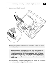
... 1 on the module and pin 1 on the socket. As a precaution, touch any exposed metal part on the metal chassis (preferably the metal part on the power supply) before handling an add-in card to side. ! Static electricity in card by its edges and do not touch any components or contacts on the...
... 1 on the module and pin 1 on the socket. As a precaution, touch any exposed metal part on the metal chassis (preferably the metal part on the power supply) before handling an add-in card to side. ! Static electricity in card by its edges and do not touch any components or contacts on the...
System Reference Manual
Page 48
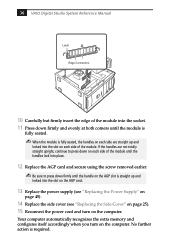
... are not totally straight upright, continue to press down firmly until the module is fully seated. ✍ When the module is required. 36 VAIO Digital Studio System Reference Manual Latch Edge Connectors 10 Carefully but firmly insert the edge of the module into the socket. 11 Press down firmly...lock into the slot on the AGP card. 13 Replace the power supply (see "Replacing the Power Supply" on page 45). 14 Replace the side cover (see "Replacing the Side Cover" on page 25). 15 Reconnect the power cord and turn on the computer. If the handles are straight up and locked into place. 12...
... are not totally straight upright, continue to press down firmly until the module is fully seated. ✍ When the module is required. 36 VAIO Digital Studio System Reference Manual Latch Edge Connectors 10 Carefully but firmly insert the edge of the module into the socket. 11 Press down firmly...lock into the slot on the AGP card. 13 Replace the power supply (see "Replacing the Power Supply" on page 45). 14 Replace the side cover (see "Replacing the Side Cover" on page 25). 15 Reconnect the power cord and turn on the computer. If the handles are straight up and locked into place. 12...

System Reference Manual
Page 52
40 VAIO Digital Studio System Reference Manual 3 Disconnect the drive connector (A in diagram). 5 Pull out on the tab (C) that secures the drive holder to the chassis. A B C Drive connector Power supply connector Tab Disk drive holder 4 Disconnect the power connector (B in diagram).
40 VAIO Digital Studio System Reference Manual 3 Disconnect the drive connector (A in diagram). 5 Pull out on the tab (C) that secures the drive holder to the chassis. A B C Drive connector Power supply connector Tab Disk drive holder 4 Disconnect the power connector (B in diagram).
System Reference Manual
Page 56
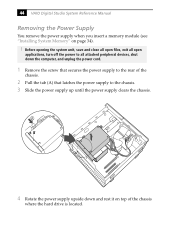
... rest it on page 34). ! A 4 Rotate the power supply upside down the computer, and unplug the power cord. 1 Remove the screw that secures the power supply to the rear of the chassis where the hard drive is located. 44 VAIO Digital Studio System Reference Manual Removing the Power Supply You remove the power supply when you insert a memory module (see "Installing...
... rest it on page 34). ! A 4 Rotate the power supply upside down the computer, and unplug the power cord. 1 Remove the screw that secures the power supply to the rear of the chassis where the hard drive is located. 44 VAIO Digital Studio System Reference Manual Removing the Power Supply You remove the power supply when you insert a memory module (see "Installing...
System Reference Manual
Page 57
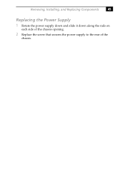
Removing, Installing, and Replacing Components 45 Replacing the Power Supply 1 Rotate the power supply down and slide it down along the rails on each side of the chassis opening. 2 Replace the screw that secures the power supply to the rear of the chassis.
Removing, Installing, and Replacing Components 45 Replacing the Power Supply 1 Rotate the power supply down and slide it down along the rails on each side of the chassis opening. 2 Replace the screw that secures the power supply to the rear of the chassis.
System Reference Manual
Page 59
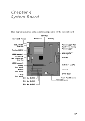
Chapter 4 System Board This chapter identifies and describes components on the system board. Keyboard, Mouse CPU Fan Processor Memory USB3, USB4, Ethernet Printer, i.LINK 1394 Header 2 Serial Port, Mic In, Line In, Line Out 1394 Header 3 Video (not used) Aux-in (not used) CD-In (not used) Slot No. 3 (PCI) Slot No. 2 (PCI) Slot No. 1 (PCI) Power Supply Fan Aux Power Supply Power Supply Secondary IDE Primary IDE Diskette Slot No. 4 (AGP) Battery CMOS Clear Front Panel Header USB23 Header 47
Chapter 4 System Board This chapter identifies and describes components on the system board. Keyboard, Mouse CPU Fan Processor Memory USB3, USB4, Ethernet Printer, i.LINK 1394 Header 2 Serial Port, Mic In, Line In, Line Out 1394 Header 3 Video (not used) Aux-in (not used) CD-In (not used) Slot No. 3 (PCI) Slot No. 2 (PCI) Slot No. 1 (PCI) Power Supply Fan Aux Power Supply Power Supply Secondary IDE Primary IDE Diskette Slot No. 4 (AGP) Battery CMOS Clear Front Panel Header USB23 Header 47
System Reference Manual
Page 61
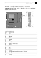
System Board 49 Power Supply and Aux Power Headers The power supply header on the system board connects to the power supply header labelled P1. 2 4 1 3 10 20 1 11 Power Supply header Pin Signal Name 1 +3.3 V 2 +3.3 V 3 Ground 4 +5 V 5 Ground 6 +5 V 7 Ground 8 PWRGD (Power Good) 9 +5 VSB 10 +12 V 11 +3.3 V 12 -12 V 13 Ground 14 PS-ON# (power supply remote on/off control) 15 Ground 16 Ground
System Board 49 Power Supply and Aux Power Headers The power supply header on the system board connects to the power supply header labelled P1. 2 4 1 3 10 20 1 11 Power Supply header Pin Signal Name 1 +3.3 V 2 +3.3 V 3 Ground 4 +5 V 5 Ground 6 +5 V 7 Ground 8 PWRGD (Power Good) 9 +5 VSB 10 +12 V 11 +3.3 V 12 -12 V 13 Ground 14 PS-ON# (power supply remote on/off control) 15 Ground 16 Ground

System Reference Manual
Page 62
50 VAIO Digital Studio System Reference Manual Power Supply header (Continued) Pin Signal Name 17 Ground 18 No Connection 19 +5 V 20 +5 V Aux Power header Pin Signal Name 1 Ground 2 Ground 3 +12 V 4 +12 V
50 VAIO Digital Studio System Reference Manual Power Supply header (Continued) Pin Signal Name 17 Ground 18 No Connection 19 +5 V 20 +5 V Aux Power header Pin Signal Name 1 Ground 2 Ground 3 +12 V 4 +12 V
VAIO User Guide
Page 60
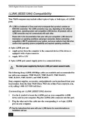
... compatibility and required operating conditions. The i.LINK connection may not communicate with your compatible i.LINK device for use . 60 Sony computer supplies, accessories, and peripherals can : ❑ supply power from the Sony VAIO Direct Web site at http://vaio.sonystyle.com, or by the 6-pin i.LINK port cannot exceed 6 watts. Plug the i.LINK cable connector into the corresponding...
... compatibility and required operating conditions. The i.LINK connection may not communicate with your compatible i.LINK device for use . 60 Sony computer supplies, accessories, and peripherals can : ❑ supply power from the Sony VAIO Direct Web site at http://vaio.sonystyle.com, or by the 6-pin i.LINK port cannot exceed 6 watts. Plug the i.LINK cable connector into the corresponding...


