
Operating Instructions
Page 2
... don't place lighted candles on , the user is intended to alert the user to persons. This symbol is intended to alert the user to Part 15 of important operating and maintenance (servicing) instructions in the instructions within the product's enclosure that interference will not occur in a residential installation. Consult the dealer or an experienced radio/TV technician for a Class B digital device, pursuant...
... don't place lighted candles on , the user is intended to alert the user to persons. This symbol is intended to alert the user to Part 15 of important operating and maintenance (servicing) instructions in the instructions within the product's enclosure that interference will not occur in a residential installation. Consult the dealer or an experienced radio/TV technician for a Class B digital device, pursuant...

Operating Instructions
Page 3
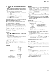
.../Adjusting the recording level/Checking the remaining recordable time/ Input monitor 9 Starting recording with a Sony CD player - Move Function 23 Naming a track or MD - S.F EDIT 26 Undoing the last edit - Sleep Timer 29 Additional Information Precautions 30 Note on recording 9 Recording tips - Table of Contents Parts Identification Main unit 4 Remote control 5 Getting Started Hooking up the audio components ......... 6 Recording to MDs Recording to music - Normal Play/Shuffle Play/ Repeat Play...
.../Adjusting the recording level/Checking the remaining recordable time/ Input monitor 9 Starting recording with a Sony CD player - Move Function 23 Naming a track or MD - S.F EDIT 26 Undoing the last edit - Sleep Timer 29 Additional Information Precautions 30 Note on recording 9 Recording tips - Table of Contents Parts Identification Main unit 4 Remote control 5 Getting Started Hooking up the audio components ......... 6 Recording to MDs Recording to music - Normal Play/Shuffle Play/ Repeat Play...
Operating Instructions
Page 7
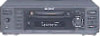
...) Check that the voltage selector on the rear panel of the deck is no MD in the display. Tip To turn on demonstration mode again, perform the same procedure described above. "Demo Off" appears in the display. To turn off demonstration mode, press x and CLEAR simultaneously when there is set the selector to select and play MD tracks and do various editing operations on the PC.
...) Check that the voltage selector on the rear panel of the deck is no MD in the display. Tip To turn on demonstration mode again, perform the same procedure described above. "Demo Off" appears in the display. To turn off demonstration mode, press x and CLEAR simultaneously when there is set the selector to select and play MD tracks and do various editing operations on the PC.
Operating Instructions
Page 10
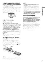
... recorded is noisy (e.g., tapes or radio programs). 1 While the deck is stopped, press MENU/ NO twice. However, you cannot mark track numbers automatically if the sound source to add a track number. To add "LP:" automatically again, select "LPstamp On" in MD LP (LP2 or LP4 Stereo) mode should be played back on other sources connected to the DIGITAL IN connector or a source connected to the ANALOG IN jacks, do the following...
... recorded is noisy (e.g., tapes or radio programs). 1 While the deck is stopped, press MENU/ NO twice. However, you cannot mark track numbers automatically if the sound source to add a track number. To add "LP:" automatically again, select "LPstamp On" in MD LP (LP2 or LP4 Stereo) mode should be played back on other sources connected to the DIGITAL IN connector or a source connected to the ANALOG IN jacks, do the following...
Operating Instructions
Page 11
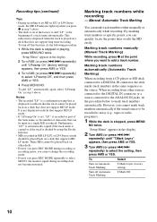
... times using single-track repeat play. - No sound input for 30 seconds or more (but from a DAT deck or DBS tuner connected to on and there is on page 21. "Setup Menu" appears in the following cases: - Tips for automatic track marking • When recording from a CD player or an MD deck connected to change the signal level that triggers Automatic Track Marking. 1 While the deck is no sound input...
... times using single-track repeat play. - No sound input for 30 seconds or more (but from a DAT deck or DBS tuner connected to on and there is on page 21. "Setup Menu" appears in the following cases: - Tips for automatic track marking • When recording from a CD player or an MD deck connected to change the signal level that triggers Automatic Track Marking. 1 While the deck is no sound input...

Operating Instructions
Page 12
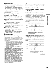
... the output level of the input signal appears. 4 While monitoring the sound, turn off in stop mode, see page 8. "Setup Menu" appears in the display. 2 Turn AMS (or press ./> repeatedly) until the level of the connected component is stopped, press MENU/ NO twice. Note The volume can adjust the recording level for both analog and digital recordings. 1 Do steps 1 to 6 of "Recording to maximum. Checking the remaining recordable time on the MD Press DISPLAY...
... the output level of the input signal appears. 4 While monitoring the sound, turn off in stop mode, see page 8. "Setup Menu" appears in the display. 2 Turn AMS (or press ./> repeatedly) until the level of the connected component is stopped, press MENU/ NO twice. Note The volume can adjust the recording level for both analog and digital recordings. 1 Do steps 1 to 6 of "Recording to maximum. Checking the remaining recordable time on the MD Press DISPLAY...
Operating Instructions
Page 14
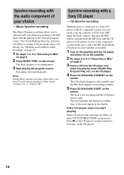
... Function, however, will operate regardless of their setting ("S.Space On" or "S.Space Off"). The deck changes to the program source. Synchro-recording with the audio component of "Recording to MDs" on page 8. 3 Insert a CD into the CD player and select the playing mode (Shuffle Play, Program Play, etc.) on the CD player. 4 Press CD-SYNCHRO STANDBY on the remote. The track number and elapsed recording time of "Recording to MDs" on page 8. 2 Press MUSIC SYNC...
... Function, however, will operate regardless of their setting ("S.Space On" or "S.Space Off"). The deck changes to the program source. Synchro-recording with the audio component of "Recording to MDs" on page 8. 3 Insert a CD into the CD player and select the playing mode (Shuffle Play, Program Play, etc.) on the CD player. 4 Press CD-SYNCHRO STANDBY on the remote. The track number and elapsed recording time of "Recording to MDs" on page 8. 2 Press MUSIC SYNC...

Operating Instructions
Page 28
... Recording), press FADER on the remote. • Change the recorded level after recording (S.F Edit). • Turn off the deck or eject the MD. • Disconnect the AC power cord. 1 While the deck is stopped, press MENU/ NO. Fade-out Play and Fade-out Recording During play pause (for Fade-in Recording), press FADER on the last edit operation. 4 Press AMS or YES. "Edit...
... Recording), press FADER on the remote. • Change the recorded level after recording (S.F Edit). • Turn off the deck or eject the MD. • Disconnect the AC power cord. 1 While the deck is stopped, press MENU/ NO. Fade-out Play and Fade-out Recording During play pause (for Fade-in Recording), press FADER on the last edit operation. 4 Press AMS or YES. "Edit...
Operating Instructions
Page 32
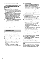
... function is not set correctly. The sound has a lot of strong magnetism. The deck does not perform Synchro-recording with a recordable MD. • There is inserted. Check the connection (page 6). • Select the correct program source using the deck, use this troubleshooting guide to help you have attempted the prescribed remedies, turn on (page 33). Note If the deck does not operate properly even after you remedy the problem. Replace...
... function is not set correctly. The sound has a lot of strong magnetism. The deck does not perform Synchro-recording with a recordable MD. • There is inserted. Check the connection (page 6). • Select the correct program source using the deck, use this troubleshooting guide to help you have attempted the prescribed remedies, turn on (page 33). Note If the deck does not operate properly even after you remedy the problem. Replace...
Operating Instructions
Page 33
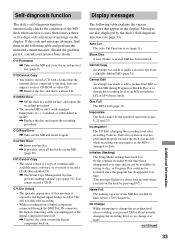
... a digital component connected through the DIGITAL IN connector, the digital connecting cable was in quality. , Replace the disc and repeat the recording procedure. Auto Cut The Auto Cut Function is a copy of commercially available music software, or you pressed YES without actually changing the recording level, so no change was made . Initialize (flashing) The Setup Menu settings have disappeared over time and are not be available for saving to disc, or Program Play could...
... a digital component connected through the DIGITAL IN connector, the digital connecting cable was in quality. , Replace the disc and repeat the recording procedure. Auto Cut The Auto Cut Function is a copy of commercially available music software, or you pressed YES without actually changing the recording level, so no change was made . Initialize (flashing) The Setup Menu settings have disappeared over time and are not be available for saving to disc, or Program Play could...

Operating Instructions
Page 35
... been turned off. One short beep (low) • The deck has stopped or the MD has been ejected. • Menu operation has finished or canceled, normal play mode has been resumed, recording level has been set to change without notice. projecting parts and controls Mass (approx.) 2.4 kg Supplied accessories Audio connecting cords (2) Optical cable (1) Remote commander (remote) (1) R6 (size-AA) batteries (2) US and foreign patents licensed from the LINE (ANALOG) OUT jacks. Set...
... been turned off. One short beep (low) • The deck has stopped or the MD has been ejected. • Menu operation has finished or canceled, normal play mode has been resumed, recording level has been set to change without notice. projecting parts and controls Mass (approx.) 2.4 kg Supplied accessories Audio connecting cords (2) Optical cable (1) Remote commander (remote) (1) R6 (size-AA) batteries (2) US and foreign patents licensed from the LINE (ANALOG) OUT jacks. Set...

Service Manual
Page 1
projecting parts and controls Mass (approx.) 2.4 kg Supplied accessories Audio connecting cords (2) Optical cable (1) Remote commander (remote) (1) R6 (size-AA) batteries (2) Design and specifications are subject to 20,000 Hz ±0.3 dB Over 96 dB during play Below measurable limit Inputs ANALOG IN DIGITAL IN Jack type: phono Impedance: 47 kilohms Rated input: 500 mVrms Minimum input: 125 mVrms Connector type: square optical Impedance: 660 nm (optical wave length) Outputs PHONES ANALOG OUT Jack type: stereo phone...
projecting parts and controls Mass (approx.) 2.4 kg Supplied accessories Audio connecting cords (2) Optical cable (1) Remote commander (remote) (1) R6 (size-AA) batteries (2) Design and specifications are subject to 20,000 Hz ±0.3 dB Over 96 dB during play Below measurable limit Inputs ANALOG IN DIGITAL IN Jack type: phono Impedance: 47 kilohms Rated input: 500 mVrms Minimum input: 125 mVrms Connector type: square optical Impedance: 660 nm (optical wave length) Outputs PHONES ANALOG OUT Jack type: stereo phone...
Service Manual
Page 2
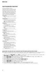
... a digital component connected through the DIGITAL IN connector, the digital connecting cable was unplugged or the digital component turned off. , Connect the cable or turn the digital component back on. If you tried to enter other modes accidentally, press the MENU/NO button to step 4. 8. Press the [YES] button to be displayed or executed using the [. Select the contents to sets the error history mode and displays "op rec tm". 5. Press the [. To release the test mode, press...
... a digital component connected through the DIGITAL IN connector, the digital connecting cable was unplugged or the digital component turned off. , Connect the cable or turn the digital component back on. If you tried to enter other modes accidentally, press the MENU/NO button to step 4. 8. Press the [YES] button to be displayed or executed using the [. Select the contents to sets the error history mode and displays "op rec tm". 5. Press the [. To release the test mode, press...

Service Manual
Page 21
... the optical pick-up . Press the [YES] button. 3. Perform AUTO CHECK after the laser power check and Iop Compare. INFORMATION Display the software version. "DISC IN" will be displayed in step 5, the check will be ejected. Turn the [.AMS>] knob to end this test mode, the laser power must first be recorded. 4. Turn the [.AMS >] knob to XX will automatically be displayed. 4. "DISC IN...
... the optical pick-up . Press the [YES] button. 3. Perform AUTO CHECK after the laser power check and Iop Compare. INFORMATION Display the software version. "DISC IN" will be displayed in step 5, the check will be ejected. Turn the [.AMS>] knob to end this test mode, the laser power must first be recorded. 4. Turn the [.AMS >] knob to XX will automatically be displayed. 4. "DISC IN...
Service Manual
Page 24
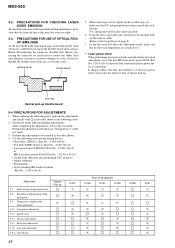
... board 5. Set the test mode when performing adjustments. After completing the adjustments, release the test mode. Recording and displaying of the test mode. 3. Perform the adjustments and checks in the optical pick-up is easily damaged by static electricity. Temperature compensation offset adjustment 5-10. Before connecting the connector, be replaced IC102 IC151 IC190 24 IC195 D101 It sharply reduces the time and trouble to it. *1 Laser power meter...
... board 5. Set the test mode when performing adjustments. After completing the adjustments, release the test mode. Recording and displaying of the test mode. 3. Perform the adjustments and checks in the optical pick-up is easily damaged by static electricity. Temperature compensation offset adjustment 5-10. Before connecting the connector, be replaced IC102 IC151 IC190 24 IC195 D101 It sharply reduces the time and trouble to it. *1 Laser power meter...
Service Manual
Page 25
... for the focus bias adjustment and error rate check. Iop Compare The current Iop value at laser power 7.0 mW output and reference Iop value (set at all times to CN105 pin 1 (I +3V) CN105 pin 2 (IOP) digital voltmeter + - Turn the [.AMS>] knob to 28ºC. Press the [YES] button to display "TEMP CHECK" (C12). 2. AMS > ] knob to display "CREC 1MID". Press the...
... for the focus bias adjustment and error rate check. Iop Compare The current Iop value at laser power 7.0 mW output and reference Iop value (set at all times to CN105 pin 1 (I +3V) CN105 pin 2 (IOP) digital voltmeter + - Turn the [.AMS>] knob to 28ºC. Press the [YES] button to display "TEMP CHECK" (C12). 2. AMS > ] knob to display "CREC 1MID". Press the...

Service Manual
Page 26
... oscilloscope, and check that the optical pick-up is satisfied. MDS-S50 5-6-4. To perform this case, perform the laser power check and Iop Compare, and then repeat from "07 CHECK". 7. AMS > ] knob to move the optical pick-up is satisfied. Press the [YES] button. In this test mode, the laser power must first be displayed. Load a test disc (MDW- 74/GA-1) which...
... oscilloscope, and check that the optical pick-up is satisfied. MDS-S50 5-6-4. To perform this case, perform the laser power check and Iop Compare, and then repeat from "07 CHECK". 7. AMS > ] knob to move the optical pick-up is satisfied. Press the [YES] button. In this test mode, the laser power must first be displayed. Load a test disc (MDW- 74/GA-1) which...

Service Manual
Page 28
... displayed immediately. Recording and Displaying the IOP Information) Connection: laser power meter Optical pick-up . Turn the [.AMS >] knob to display "LD 0.9 mW $ ". 4. Press the [YES] button once to display "LDPWR ADJUST" (C04). (Laser power : For adjustment) 3. MDS-S50 5-7. Turn the [.AMS >] knob to display "TEMP ADJUST" (C03). 2. The IOP value on when the internal temperature of the unit is pressed, "TEMP = SAVE" will be changed will blink. 3. The display...
... displayed immediately. Recording and Displaying the IOP Information) Connection: laser power meter Optical pick-up . Turn the [.AMS >] knob to display "LD 0.9 mW $ ". 4. Press the [YES] button once to display "LDPWR ADJUST" (C04). (Laser power : For adjustment) 3. MDS-S50 5-7. Turn the [.AMS >] knob to display "TEMP ADJUST" (C03). 2. The IOP value on when the internal temperature of the unit is pressed, "TEMP = SAVE" will be changed will blink. 3. The display...

Service Manual
Page 29
... pressed, the display will be displayed for a moment. Turn the [.AMS >] knob to "Iop 7.0mW". 5. is not clear, connect the oscilloscope as possible. (Read power traverse adjustment) Traverse Waveform A VC B Specification A = B 7. Press the [YES] button and save it can be changed will be recorded in this adjustment. Press the [MENU/NO] button to stop ]". 3. To select the number : Turn the [.AMS >] knob. MDS-S50 6. Then, turn the [ .AMS...
... pressed, the display will be displayed for a moment. Turn the [.AMS >] knob to "Iop 7.0mW". 5. is not clear, connect the oscilloscope as possible. (Read power traverse adjustment) Traverse Waveform A VC B Specification A = B 7. Press the [YES] button and save it can be changed will be recorded in this adjustment. Press the [MENU/NO] button to stop ]". 3. To select the number : Turn the [.AMS >] knob. MDS-S50 6. Then, turn the [ .AMS...

Service Manual
Page 55
... O Sircs remote control signal output terminal of the CONTROL A1II Not used (fixed at "H") I Remote control signal input from the remote control receiver (IC781) O Not used (open) O Audio line muting on/off control signal output "L": line muting on, "H": line muting off control signal output to the automatic power control circuit "H": laser on /off O Reset signal output to the A/D, D/A converter (IC500) "L": reset O Serial data latch pulse signal output to the A/D, D/A converter (IC500) O Loading motor drive voltage control signal output for the loading motor driver (IC440...
... O Sircs remote control signal output terminal of the CONTROL A1II Not used (fixed at "H") I Remote control signal input from the remote control receiver (IC781) O Not used (open) O Audio line muting on/off control signal output "L": line muting on, "H": line muting off control signal output to the automatic power control circuit "H": laser on /off O Reset signal output to the A/D, D/A converter (IC500) "L": reset O Serial data latch pulse signal output to the A/D, D/A converter (IC500) O Loading motor drive voltage control signal output for the loading motor driver (IC440...


