
Operating Instructions
Page 5
... KP-53HS10 and KP-61HS10. TruSurround and SRS technology is for 720p format). Manufactured under license from SRS Labs, Inc. Picture & Picture (P&P) with four-times higher density than the conventional NTSC picture. (not available for purchasing the Sony Color Rear Video ...Projection TV. "Dolby," and the double-D symbol ; are trademarks of SRS Labs, Inc. By using the VIDEO 5 (DTV) IN jacks, you can connect a DTV (digital television) receiver to view DTV programs. The VIDEO 5 (DTV) IN jacks also function as R/ G/B connectors with SYNC signal (HD...
... KP-53HS10 and KP-61HS10. TruSurround and SRS technology is for 720p format). Manufactured under license from SRS Labs, Inc. Picture & Picture (P&P) with four-times higher density than the conventional NTSC picture. (not available for purchasing the Sony Color Rear Video ...Projection TV. "Dolby," and the double-D symbol ; are trademarks of SRS Labs, Inc. By using the VIDEO 5 (DTV) IN jacks, you can connect a DTV (digital television) receiver to view DTV programs. The VIDEO 5 (DTV) IN jacks also function as R/ G/B connectors with SYNC signal (HD...

Operating Instructions
Page 11
...S IN OUT CONTROL S IN OUT AUX IN OUT VIDEO 4 VIDEO 5 (DTV) SELECT IN VIDEO 1 VIDEO 3 HD VD S VIDEO VIDEO L (MONO) AUDIO R Y Y/G L PB PB/B (MONO) PR PR/R R COMPONENT AUDIO VHF/UHF VIDEO L AUDIO R Making Connections Connecting Directly to Sony products and allow greater control of 300-ohm twin ... into connection. A • VHF only or • VHF/UHF or • Cable 75-ohm coaxial cable (Rear of projection TV) VHF/UHF B (Rear of all Sony equipment. Installing and Connecting the Projection TV Composite video cable for a DTV receiver Push into connection. G/Y...
...S IN OUT CONTROL S IN OUT AUX IN OUT VIDEO 4 VIDEO 5 (DTV) SELECT IN VIDEO 1 VIDEO 3 HD VD S VIDEO VIDEO L (MONO) AUDIO R Y Y/G L PB PB/B (MONO) PR PR/R R COMPONENT AUDIO VHF/UHF VIDEO L AUDIO R Making Connections Connecting Directly to Sony products and allow greater control of 300-ohm twin ... into connection. A • VHF only or • VHF/UHF or • Cable 75-ohm coaxial cable (Rear of projection TV) VHF/UHF B (Rear of all Sony equipment. Installing and Connecting the Projection TV Composite video cable for a DTV receiver Push into connection. G/Y...

Operating Instructions
Page 13
... AUDIO and S VIDEO* cables, connect AUDIO and S VIDEO OUT on the VCR to the left (MONO) input on the projection TV (White-AUDIO Left, Red-AUDIO Right). * If your VCR is not equipped with S VIDEO, use a VIDEO cable (yellow) instead of projection TV) CONTROL S IN OUT AUX IN OUT VIDEO 4 VIDEO 5 (DTV) SELECT IN VIDEO 1 VIDEO 3 HD VD S VIDEO VIDEO L (MONO) AUDIO...
... AUDIO and S VIDEO* cables, connect AUDIO and S VIDEO OUT on the VCR to the left (MONO) input on the projection TV (White-AUDIO Left, Red-AUDIO Right). * If your VCR is not equipped with S VIDEO, use a VIDEO cable (yellow) instead of projection TV) CONTROL S IN OUT AUX IN OUT VIDEO 4 VIDEO 5 (DTV) SELECT IN VIDEO 1 VIDEO 3 HD VD S VIDEO VIDEO L (MONO) AUDIO...
Operating Instructions
Page 14
...). * If your VCR is connected to by pressing TV/VIDEO. Note: • To view scrambled channels through the cable box, select the video input which the cable box is not equipped with S VIDEO, use a VIDEO cable (yellow) instead of projection TV) CONTROL S IN OUT AUX IN OUT VIDEO 4 VIDEO 5 (DTV) SELECT IN VIDEO 1 VIDEO 3 HD VD S VIDEO VIDEO L (MONO) AUDIO R Y Y/G L PB PB...
...). * If your VCR is connected to by pressing TV/VIDEO. Note: • To view scrambled channels through the cable box, select the video input which the cable box is not equipped with S VIDEO, use a VIDEO cable (yellow) instead of projection TV) CONTROL S IN OUT AUX IN OUT VIDEO 4 VIDEO 5 (DTV) SELECT IN VIDEO 1 VIDEO 3 HD VD S VIDEO VIDEO L (MONO) AUDIO R Y Y/G L PB PB...

Operating Instructions
Page 15
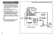
... jacks, proceed to step 2 in "Connecting a DTV (digital television) receiver with the G/B/R/ HD/VD jacks 1 Attach the coaxial cable from the roof antenna to VHF/UHF on the DTV receiver. 2 Using a composite video cable for DTV receiver, connect G, B, R, HD and VD of VIDEO OUT on the DTV receiver to G, B, R, HD and VD respectively of VIDEO 5 (DTV) IN on page...
... jacks, proceed to step 2 in "Connecting a DTV (digital television) receiver with the G/B/R/ HD/VD jacks 1 Attach the coaxial cable from the roof antenna to VHF/UHF on the DTV receiver. 2 Using a composite video cable for DTV receiver, connect G, B, R, HD and VD of VIDEO OUT on the DTV receiver to G, B, R, HD and VD respectively of VIDEO 5 (DTV) IN on page...

Operating Instructions
Page 16
... differently. Connecting a DTV (digital television) receiver with the Y/PB/ PR (component video input) jacks 1 Attach the coaxial cable from the roof antenna to VHF/UHF on the DTV receiver. 2 Using three VIDEO cables, connect Y, PB and PR of COMPONENT VIDEO OUT on... Cr or R-Y. Connect PB (blue) to Y. If so, connect as follows: Connect Y (green) to CB, Cb or B-Y. Disconnect all power sources before making any connections. 2 VMC-10HG (not supplied) PB Y PR CONTROL S IN OUT AUX IN OUT VIDEO 4 VIDEO 5 (DTV) SELECT DTV receiver IN VIDEO 1 VIDEO 3 HD VD S VIDEO VIDEO L (MONO) ...
... differently. Connecting a DTV (digital television) receiver with the Y/PB/ PR (component video input) jacks 1 Attach the coaxial cable from the roof antenna to VHF/UHF on the DTV receiver. 2 Using three VIDEO cables, connect Y, PB and PR of COMPONENT VIDEO OUT on... Cr or R-Y. Connect PB (blue) to Y. If so, connect as follows: Connect Y (green) to CB, Cb or B-Y. Disconnect all power sources before making any connections. 2 VMC-10HG (not supplied) PB Y PR CONTROL S IN OUT AUX IN OUT VIDEO 4 VIDEO 5 (DTV) SELECT DTV receiver IN VIDEO 1 VIDEO 3 HD VD S VIDEO VIDEO L (MONO) ...

Operating Instructions
Page 17
..., RedAUDIO Right). Disconnect all power sources before making any connections. (Rear of projection TV) CONTROL S IN OUT AUX IN OUT VIDEO 4 VIDEO 5 (DTV) SELECT IN VIDEO 1 VIDEO 3 HD VD Cable/ Satellite antenna Antenna cable 21 S VIDEO VIDEO L (MONO) AUDIO R Y Y/G L PB PB/B (MONO) PR PR/R R COMPONENT AUDIO S-VIDEO AUDIO-L AUDIO-R VHF/UHF VIDEO L AUDIO R SATELLITE IN LINE OUT DBS VHF/UHF AUDIO...
..., RedAUDIO Right). Disconnect all power sources before making any connections. (Rear of projection TV) CONTROL S IN OUT AUX IN OUT VIDEO 4 VIDEO 5 (DTV) SELECT IN VIDEO 1 VIDEO 3 HD VD Cable/ Satellite antenna Antenna cable 21 S VIDEO VIDEO L (MONO) AUDIO R Y Y/G L PB PB/B (MONO) PR PR/R R COMPONENT AUDIO S-VIDEO AUDIO-L AUDIO-R VHF/UHF VIDEO L AUDIO R SATELLITE IN LINE OUT DBS VHF/UHF AUDIO...

Operating Instructions
Page 18
... and S VIDEO* cables, connect AUDIO and S VIDEO OUT on the VCR to by pressing TV/VIDEO on the projection TV (White-AUDIO Left, Red-AUDIO Right). * If your DBS receiver or VCR is not equipped with S VIDEO, use a VIDEO cable (yellow) instead of projection TV) CONTROL S IN OUT AUX IN OUT VIDEO 4 VIDEO 5 (DTV) SELECT IN VIDEO 1 VIDEO 3 HD VD Coaxial...
... and S VIDEO* cables, connect AUDIO and S VIDEO OUT on the VCR to by pressing TV/VIDEO on the projection TV (White-AUDIO Left, Red-AUDIO Right). * If your DBS receiver or VCR is not equipped with S VIDEO, use a VIDEO cable (yellow) instead of projection TV) CONTROL S IN OUT AUX IN OUT VIDEO 4 VIDEO 5 (DTV) SELECT IN VIDEO 1 VIDEO 3 HD VD Coaxial...

Operating Instructions
Page 20
... OUT OUT IN 1 Disconnect all power sources before making any connections. (Rear of projection TV) CONTROL S IN OUT AUX IN OUT VIDEO 4 VIDEO 5 (DTV) SELECT IN VIDEO 1 VIDEO 3 HD VD S VIDEO VIDEO L (MONO) AUDIO R Y Y/G L PB PB/B (MONO) PR PR/R R COMPONENT AUDIO VIDEO VIDEO AUDIO-L AUDIO-L AUDIO-R AUDIO-R VHF/UHF VIDEO L AUDIO VCR (for recording to the VCR LINE INPUT (see "SELECT OUT...
... OUT OUT IN 1 Disconnect all power sources before making any connections. (Rear of projection TV) CONTROL S IN OUT AUX IN OUT VIDEO 4 VIDEO 5 (DTV) SELECT IN VIDEO 1 VIDEO 3 HD VD S VIDEO VIDEO L (MONO) AUDIO R Y Y/G L PB PB/B (MONO) PR PR/R R COMPONENT AUDIO VIDEO VIDEO AUDIO-L AUDIO-L AUDIO-R AUDIO-R VHF/UHF VIDEO L AUDIO VCR (for recording to the VCR LINE INPUT (see "SELECT OUT...

Operating Instructions
Page 21
Connecting the DVD Player through other video equipment will cause unwanted picture noise. 17 S VIDEO (Rear of information, picture noise may appear. Note: • Since the high quality pictures on a DVD disc contain a lot of projection TV) CONTROL S IN OUT AUX IN OUT VIDEO 4 VIDEO 5 (DTV) SELECT IN VIDEO 1 VIDEO 3 HD VD S VIDEO VIDEO L (MONO) AUDIO R Y Y/G L PB PB/B (MONO) PR PR/R R COMPONENT...
Connecting the DVD Player through other video equipment will cause unwanted picture noise. 17 S VIDEO (Rear of information, picture noise may appear. Note: • Since the high quality pictures on a DVD disc contain a lot of projection TV) CONTROL S IN OUT AUX IN OUT VIDEO 4 VIDEO 5 (DTV) SELECT IN VIDEO 1 VIDEO 3 HD VD S VIDEO VIDEO L (MONO) AUDIO R Y Y/G L PB PB/B (MONO) PR PR/R R COMPONENT...

Operating Instructions
Page 22
...) SELECT VMC-10HG (not supplied) AUX IN VIDEO 1 VIDEO 3 HD VD S VIDEO VIDEO L (MONO) AUDIO R Y Y/G L PB PB/B (MONO) PR PR/R R COMPONENT AUDIO VHF/UHF VIDEO L AUDIO R 2 PR PB Y DVD LINE OUT S VIDEO OUT COMPONENT VIDEO OUT S-LINK DIGITAL OUT R-AUDIO 1-L VIDEO Y PB PR OPTICAL COAXIAL AUDIO-L AUDIO-R 1 RK-74A (not supplied) Connect the DVD Player directly to CR, Cr or...
...) SELECT VMC-10HG (not supplied) AUX IN VIDEO 1 VIDEO 3 HD VD S VIDEO VIDEO L (MONO) AUDIO R Y Y/G L PB PB/B (MONO) PR PR/R R COMPONENT AUDIO VHF/UHF VIDEO L AUDIO R 2 PR PB Y DVD LINE OUT S VIDEO OUT COMPONENT VIDEO OUT S-LINK DIGITAL OUT R-AUDIO 1-L VIDEO Y PB PR OPTICAL COAXIAL AUDIO-L AUDIO-R 1 RK-74A (not supplied) Connect the DVD Player directly to CR, Cr or...

Operating Instructions
Page 23
...) (Rear of VIDEO 1 IN on the projection TV to MONITOR OUT on the AV receiver. 4 Using an AUDIO/VIDEO cable, connect SELECT OUT on the projection TV to AUDIO/VIDEO 2 IN on the AV receiver. 5 Using an AUDIO/VIDEO cable, connect the video equipment ...input to the AV receiver (VIDEO 1). (see "CHANNEL FIX" on page 38) Disconnect all audio and video equipment, connect an AV receiver. 1-2Perform as described on page 9. 3 Using a VIDEO cable, connect VIDEO of projection TV) 2 CONTROL S IN OUT AUX IN OUT VIDEO 4 VIDEO 5 (DTV) SELECT IN VIDEO 1 VIDEO 3 HD VD S VIDEO VIDEO L (MONO) AUDIO R...
...) (Rear of VIDEO 1 IN on the projection TV to MONITOR OUT on the AV receiver. 4 Using an AUDIO/VIDEO cable, connect SELECT OUT on the projection TV to AUDIO/VIDEO 2 IN on the AV receiver. 5 Using an AUDIO/VIDEO cable, connect the video equipment ...input to the AV receiver (VIDEO 1). (see "CHANNEL FIX" on page 38) Disconnect all audio and video equipment, connect an AV receiver. 1-2Perform as described on page 9. 3 Using a VIDEO cable, connect VIDEO of projection TV) 2 CONTROL S IN OUT AUX IN OUT VIDEO 4 VIDEO 5 (DTV) SELECT IN VIDEO 1 VIDEO 3 HD VD S VIDEO VIDEO L (MONO) AUDIO R...

Operating Instructions
Page 47
..." on the rear of the projection TV. Your password is selected. Move Select Exit MENU (continued) 43 Adjusting Your SET UP (menus) Input signal selection from the DTV receiver Select R.G.B when you connect a DTV receiver to the G/B/R/HD/VD jacks of America (MPAA) Guidelines to 4:3. TV ratings), and Motion Picture Association of VIDEO 5 (DTV...
..." on the rear of the projection TV. Your password is selected. Move Select Exit MENU (continued) 43 Adjusting Your SET UP (menus) Input signal selection from the DTV receiver Select R.G.B when you connect a DTV receiver to the G/B/R/HD/VD jacks of America (MPAA) Guidelines to 4:3. TV ratings), and Motion Picture Association of VIDEO 5 (DTV...

Operating Instructions
Page 63
...KP-61HS10) Supplied accessories Remote control RM-Y902 (1) Batteries size AA (R6) (2) Optional accessories Connecting cables RK-G34, RK-74A, RKG-69HG, VMC-10HG, VMC-720M, VMC-810S/820S, YC-15V/30V U/V mixer EAC-66 Design and specifications are not compatible with a computer's 5BNC (R/G/B/HD/VD) video... hybrid lens F1.1 Television system American TV standard Channel coverage VHF: 2-13/UHF: 14-69/CATV: 1-125 Antenna 75 ohm external terminal for VHF/UHF Screen size (measured diagonally) 53 inches (KP-53HS10) 61 inches (KP-61HS10) Inputs/outputs VIDEO 1/3 IN VIDEO 2 INPUT S VIDEO IN (4-pin mini DIN...
...KP-61HS10) Supplied accessories Remote control RM-Y902 (1) Batteries size AA (R6) (2) Optional accessories Connecting cables RK-G34, RK-74A, RKG-69HG, VMC-10HG, VMC-720M, VMC-810S/820S, YC-15V/30V U/V mixer EAC-66 Design and specifications are not compatible with a computer's 5BNC (R/G/B/HD/VD) video... hybrid lens F1.1 Television system American TV standard Channel coverage VHF: 2-13/UHF: 14-69/CATV: 1-125 Antenna 75 ohm external terminal for VHF/UHF Screen size (measured diagonally) 53 inches (KP-53HS10) 61 inches (KP-61HS10) Inputs/outputs VIDEO 1/3 IN VIDEO 2 INPUT S VIDEO IN (4-pin mini DIN...

Operating Instructions
Page 64
... INDEX 31 CHANNEL SET UP menu operations 37 CHANNEL SKIP 37 60 Coaxial cable 6, 9 COLOR 34 Connecting Projection TV to amplifier that supports Dolby Pro Logic decoder 21 antenna 7 audio system 20 ... setting 39 FLASH FOCUS 24 FREEZE button 25, 29, 30 FREEZE MODE NORMAL 42 TWIN 42 G G/B/R/HD/VD 11, 43 H Hookups 7 HUE 34 J Joystick 22 JUMP button 25 L LANGUAGE selection 41 Learning...STEREO 35 MUTING button 25 N NR 35 O ON/OFF TIMER 37 On-line help 22 Operating video equipment 53 P PARENTAL CONTROL 43 Password 43 PICTURE 34 PICTURE MODE button 34 Picture-and-Picture ...
... INDEX 31 CHANNEL SET UP menu operations 37 CHANNEL SKIP 37 60 Coaxial cable 6, 9 COLOR 34 Connecting Projection TV to amplifier that supports Dolby Pro Logic decoder 21 antenna 7 audio system 20 ... setting 39 FLASH FOCUS 24 FREEZE button 25, 29, 30 FREEZE MODE NORMAL 42 TWIN 42 G G/B/R/HD/VD 11, 43 H Hookups 7 HUE 34 J Joystick 22 JUMP button 25 L LANGUAGE selection 41 Learning...STEREO 35 MUTING button 25 N NR 35 O ON/OFF TIMER 37 On-line help 22 Operating video equipment 53 P PARENTAL CONTROL 43 Password 43 PICTURE 34 PICTURE MODE button 34 Picture-and-Picture ...


