Revision History
Page 3
... Safety Check Out 3 1-3. Leakage Test 3 1-4. Accessing Diagnostic Menu 21 5-2. Factory Reset 22 5-5. Overview of LCD Panel 3 1-2. GP Board Removal (KLV-26,32,32/H/S S400A 9 3-6. Rear Cabinet and Stand Assy 29 7-2-2. Caution Handling of Control Buttons 5 2-2. Standby LED Error...KLV-26S400A 26 7-1-1. BG1, Power Unit (G2D), HG4A Boards, Speakers, Bezel Assy and LCD Panel 34 8. Accessing Service Menu 21 5-4. Rear Cabinet and Stand Assy 32 7-3-2. Circuit Board Location 24 6-3. Chassis-1 27 7-1-3. ELECTRICAL PARTS LIST 35 OPERATING INSTRUCTIONS - 2 ...
... Safety Check Out 3 1-3. Leakage Test 3 1-4. Accessing Diagnostic Menu 21 5-2. Factory Reset 22 5-5. Overview of LCD Panel 3 1-2. GP Board Removal (KLV-26,32,32/H/S S400A 9 3-6. Rear Cabinet and Stand Assy 29 7-2-2. Caution Handling of Control Buttons 5 2-2. Standby LED Error...KLV-26S400A 26 7-1-1. BG1, Power Unit (G2D), HG4A Boards, Speakers, Bezel Assy and LCD Panel 34 8. Accessing Service Menu 21 5-4. Rear Cabinet and Stand Assy 32 7-3-2. Circuit Board Location 24 6-3. Chassis-1 27 7-1-3. ELECTRICAL PARTS LIST 35 OPERATING INSTRUCTIONS - 2 ...
Revision History
Page 4
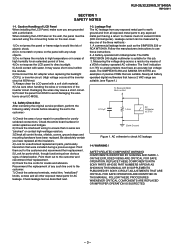
...IS SUSPECTED. - 3 - Damaging the wires may cause short circuit within the module. 6) Disconnect the AC adapter when replacing the backlight (CCFL) or inverter circuit. (High voltage occurs at the inverter circuit at 650Vrms) 7) Always clean the LCD panel with water. Caution Handling of passive VOMs that no ...wires are suitable. When installing the LCD Panel on the wall, the panel must have been replaced. Check the entire board surface for an extended period of electric shock. 2) Do not scratch or press on Set 1-2. KLV-26,32,32/H/S,37 S400A RM-GA011 SECTION 1 SAFETY...
...IS SUSPECTED. - 3 - Damaging the wires may cause short circuit within the module. 6) Disconnect the AC adapter when replacing the backlight (CCFL) or inverter circuit. (High voltage occurs at the inverter circuit at 650Vrms) 7) Always clean the LCD panel with water. Caution Handling of passive VOMs that no ...wires are suitable. When installing the LCD Panel on the wall, the panel must have been replaced. Check the entire board surface for an extended period of electric shock. 2) Do not scratch or press on Set 1-2. KLV-26,32,32/H/S,37 S400A RM-GA011 SECTION 1 SAFETY...
Revision History
Page 5
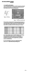
... Information The circuit boards used in order to http://www.sony-training.com - 4 - Figure 2: LF logo Figure 3: LF logo on the use Lead Free Solder material in these boards requires special precautions. It is available under the following part numbers:- For more information on circuit board The ...servicing of Lead Free Solder, please refer to guarantee optimal quality of new solder joints. KLV-26,32,32/H/S,37 S400A RM-GA011 1-5. The boards are identified by the LF logo ...
... Information The circuit boards used in order to http://www.sony-training.com - 4 - Figure 2: LF logo Figure 3: LF logo on the use Lead Free Solder material in these boards requires special precautions. It is available under the following part numbers:- For more information on circuit board The ...servicing of Lead Free Solder, please refer to guarantee optimal quality of new solder joints. KLV-26,32,32/H/S,37 S400A RM-GA011 1-5. The boards are identified by the LF logo ...

Revision History
Page 25
CIRCUIT BOARD LOCATION KLV-26,32,32/H/S,37 S400A BG1 Board Block Switch Panel GP Board (KLV-26,32,32/H/S S400A) Power Unit (G2D Board) (KLV-37S400A) HG4 Board (KLV-26,32,32/H/S S400A) HG4A Board (KLV-37S400A) - 24 - BLOCK DIAGRAM SECTION 6 DIAGRAMS Due to complexity of the board, performing component level field repairs are not recommended. Complete board replacement is required if service is necessary. 6-2. KLV-26,32,32/H/S,37 S400A RM-GA011 6-1.
CIRCUIT BOARD LOCATION KLV-26,32,32/H/S,37 S400A BG1 Board Block Switch Panel GP Board (KLV-26,32,32/H/S S400A) Power Unit (G2D Board) (KLV-37S400A) HG4 Board (KLV-26,32,32/H/S S400A) HG4A Board (KLV-37S400A) - 24 - BLOCK DIAGRAM SECTION 6 DIAGRAMS Due to complexity of the board, performing component level field repairs are not recommended. Complete board replacement is required if service is necessary. 6-2. KLV-26,32,32/H/S,37 S400A RM-GA011 6-1.
Revision History
Page 38
... EA (Silver) COMMANDER DEST. Other information remains the same as in the original issue. DIAGRAMS 6-2. Circuit Board Location (refer page 24) HG4A Board - 37 - DISASSEMBLY 3-3. HG4A Board Removal (refer page 8) 2 Harness with connector 1 Two screws (+BVTP2 4 X 16) 3 LCD panel 5 Two screws (+BVTP2 3 X 12) 6 HG4A board 4 One connector Guide Light Bezel assy SECTION...
... EA (Silver) COMMANDER DEST. Other information remains the same as in the original issue. DIAGRAMS 6-2. Circuit Board Location (refer page 24) HG4A Board - 37 - DISASSEMBLY 3-3. HG4A Board Removal (refer page 8) 2 Harness with connector 1 Two screws (+BVTP2 4 X 16) 3 LCD panel 5 Two screws (+BVTP2 3 X 12) 6 HG4A board 4 One connector Guide Light Bezel assy SECTION...