
Child Safety: It Makes A Difference Where Your TV Stands
Page 1
...sets. 5 Avoid placing any items on this hidden hazard of the home with your furniture to the wall (but never screw anything directly into the TV). 3 Carefully read and understand the manufacturer's instructions and product safety notices. 4 Don't allow children to secure your family and friends. Child Safety...: It Makes A Difference Where Your TV Stands The Issue If you are like most Americans, you ! 2500 Wilson Boulevard Arlington, VA 22201 Tel 703 907 7600 Fax 703 907 7690...
...sets. 5 Avoid placing any items on this hidden hazard of the home with your furniture to the wall (but never screw anything directly into the TV). 3 Carefully read and understand the manufacturer's instructions and product safety notices. 4 Don't allow children to secure your family and friends. Child Safety...: It Makes A Difference Where Your TV Stands The Issue If you are like most Americans, you ! 2500 Wilson Boulevard Arlington, VA 22201 Tel 703 907 7600 Fax 703 907 7690...

Dimensions Diagrams
Page 1
KE-37XS910 RM-Y1001 REMOTE CONTROL MDDEEOSSDCCERRLII:PPTTIIOONN:: DIMENSIONS 37" Flat Panel TV POWER REQUIREMENTS1: 20V AC (W(WWEHHIGDDH))::T4:4 WEIGHT: 5/8 " x 27 1/4 " x 4 Approx 73 lbs 3/8 " POWER CONSUMPTION: 60Hz 360w 6w stby 23" TOP VIEW 44 5/8" SIDE VIEW 4 3/8 " S P E A K E R S FRONT AV INPUT 19" 32" CENTER FRONT VIEW 16 1/8" S P 24 3/8" E 27 1/4" A K E R S 15 1/2" CONTROL PANEL... 07656 • FAX (201) 930 7891 • www.sel.sony.com/dn Features and specifications subject to change without notice. • Non-metric weights and measurements are approximate...
KE-37XS910 RM-Y1001 REMOTE CONTROL MDDEEOSSDCCERRLII:PPTTIIOONN:: DIMENSIONS 37" Flat Panel TV POWER REQUIREMENTS1: 20V AC (W(WWEHHIGDDH))::T4:4 WEIGHT: 5/8 " x 27 1/4 " x 4 Approx 73 lbs 3/8 " POWER CONSUMPTION: 60Hz 360w 6w stby 23" TOP VIEW 44 5/8" SIDE VIEW 4 3/8 " S P E A K E R S FRONT AV INPUT 19" 32" CENTER FRONT VIEW 16 1/8" S P 24 3/8" E 27 1/4" A K E R S 15 1/2" CONTROL PANEL... 07656 • FAX (201) 930 7891 • www.sel.sony.com/dn Features and specifications subject to change without notice. • Non-metric weights and measurements are approximate...

Operating Instructions
Page 1
Flat Panel Color TV KE-37XS910/KE-42XS910 4-097-685-11 (1) Flat Panel Color TV Operating Instructions KE-37XS910 KE-42XS910 2003 Sony Corporation
Flat Panel Color TV KE-37XS910/KE-42XS910 4-097-685-11 (1) Flat Panel Color TV Operating Instructions KE-37XS910 KE-42XS910 2003 Sony Corporation

Operating Instructions
Page 3
... feet (air pressure less than private viewing of programs broadcast on the cord. NO USER-SERVICEABLE PARTS INSIDE. CAUTION When using the TV for the KE-37XS910, this Plasma Display Panel may generate a low buzzing sound as a station logo is intended to alert the user to comply with your...15.119 of the FCC rules. This is not considered a defect and is provided to insert the plug fully into the outlet, contact your Sony dealer regarding this equipment. REFER SERVICING TO QUALIFIED SERVICE PERSONNEL. These types of imprints are located at a high brightness or contrast setting, the...
... feet (air pressure less than private viewing of programs broadcast on the cord. NO USER-SERVICEABLE PARTS INSIDE. CAUTION When using the TV for the KE-37XS910, this Plasma Display Panel may generate a low buzzing sound as a station logo is intended to alert the user to comply with your...15.119 of the FCC rules. This is not considered a defect and is provided to insert the plug fully into the outlet, contact your Sony dealer regarding this equipment. REFER SERVICING TO QUALIFIED SERVICE PERSONNEL. These types of imprints are located at a high brightness or contrast setting, the...

Operating Instructions
Page 4
...the picture may be blurred or show poor color due to moisture condensation. CAUTION How to reduce the risk of Sony Corporation. When viewing programs with the following steps to reduce the risk of causing image retention: View a variety of Sony Corporation. 2 ClearEdge VM, HD Detailer,...your TV Bright, stationary images such as TV station logos are viewed. KE-37XS910 KE-42XS910 WALL MOUNT UNIT MODEL NO. BBE and BBE Symbol are trademarks of program sources or programming material. Patent No. 4,638,258 and 4,482,866. Be sure to subcontract the installation to Sony dealers...
...the picture may be blurred or show poor color due to moisture condensation. CAUTION How to reduce the risk of Sony Corporation. When viewing programs with the following steps to reduce the risk of causing image retention: View a variety of Sony Corporation. 2 ClearEdge VM, HD Detailer,...your TV Bright, stationary images such as TV station logos are viewed. KE-37XS910 KE-42XS910 WALL MOUNT UNIT MODEL NO. BBE and BBE Symbol are trademarks of program sources or programming material. Patent No. 4,638,258 and 4,482,866. Be sure to subcontract the installation to Sony dealers...

Operating Instructions
Page 5
..., refer to have the outlet changed. Grounding or Polarization This set is continuous or frequent while the TV is not being turned on the serial/model plate. Contact your dealer or Sony service center to make occasional snapping or popping sounds, particularly when being used. Wiring Unplug the AC...home, consult your dealer or service technician. Never spill liquid of power source indicated on or off when it is operating, unplug the TV and consult your dealer or local power company. Carefully observe and comply with dust and it may be operated only from heat sources. Use...
..., refer to have the outlet changed. Grounding or Polarization This set is continuous or frequent while the TV is not being turned on the serial/model plate. Contact your dealer or Sony service center to make occasional snapping or popping sounds, particularly when being used. Wiring Unplug the AC...home, consult your dealer or service technician. Never spill liquid of power source indicated on or off when it is operating, unplug the TV and consult your dealer or local power company. Carefully observe and comply with dust and it may be operated only from heat sources. Use...

Operating Instructions
Page 6
...overhang any overhanging edge is in the specified manner, referring to follow the operating instructions supplied with a dry soft cloth. Accessories Secure the TV from the unit. To remove dust from the screen, wipe it may drop and a serious injury may fall and damage the set ...and cause injury. Consult qualified service personnel. Corrosion If you carry the set , causing serious injury. Never use attachments not recommended by Sony for a long period of time, it may be necessary to shocks or vibration excessive force. Attachments Do not use strong solvents such as...
...overhang any overhanging edge is in the specified manner, referring to follow the operating instructions supplied with a dry soft cloth. Accessories Secure the TV from the unit. To remove dust from the screen, wipe it may drop and a serious injury may fall and damage the set ...and cause injury. Consult qualified service personnel. Corrosion If you carry the set , causing serious injury. Never use attachments not recommended by Sony for a long period of time, it may be necessary to shocks or vibration excessive force. Attachments Do not use strong solvents such as...

Operating Instructions
Page 7
... rest on a bed, sofa, rug or other materials. If the unit is provided, the unit may damage the AC power cord and result in the TV are provided for the grounding electrode. (Continued) 5
... rest on a bed, sofa, rug or other materials. If the unit is provided, the unit may damage the AC power cord and result in the TV are provided for the grounding electrode. (Continued) 5

Operating Instructions
Page 8
... set exhibits a distinct change in the operating instructions. s When the set . Servicing Do not attempt to drop it until you carry the TV in fire, electric shock or other than specified and without the specified number of persons. Safety Check Upon completion of the display unit cracks,... of any service or repairs to the set yourself since opening the cabinet may result. Otherwise electric shock may expose you place the TV in damage and will prevent damage to the receiver due to follow the instructions mentioned below. Moisture Do not let this television receiver ...
... set exhibits a distinct change in the operating instructions. s When the set . Servicing Do not attempt to drop it until you carry the TV in fire, electric shock or other than specified and without the specified number of persons. Safety Check Upon completion of the display unit cracks,... of any service or repairs to the set yourself since opening the cabinet may result. Otherwise electric shock may expose you place the TV in damage and will prevent damage to the receiver due to follow the instructions mentioned below. Moisture Do not let this television receiver ...

Operating Instructions
Page 11
... 13 Package Contents 13 Features 13 Setting Up the TV Overview 15 TV Controls and Connectors 16 Front Panel 16 Right Side Panel 17 Left Side Panel 18 Rear Panel 19 Installing the TV 21 Connecting the AC Power Cord 21 Preventing the TV from Falling Down 21 Storing the Cables in the ...Receiver 36 Satellite Receiver and VCR 38 DVD Player with Component Video Connectors 40 DVD Player with S VIDEO and Audio Connectors 42 Digital TV Set-Top Box with Component Video Connectors ..........43 Digital Satellite Receiver with DVI-HDTV Connector 44 Camcorder 45 Audio Receiver 46 Sub Woofer...
... 13 Package Contents 13 Features 13 Setting Up the TV Overview 15 TV Controls and Connectors 16 Front Panel 16 Right Side Panel 17 Left Side Panel 18 Rear Panel 19 Installing the TV 21 Connecting the AC Power Cord 21 Preventing the TV from Falling Down 21 Storing the Cables in the ...Receiver 36 Satellite Receiver and VCR 38 DVD Player with Component Video Connectors 40 DVD Player with S VIDEO and Audio Connectors 42 Digital TV Set-Top Box with Component Video Connectors ..........43 Digital Satellite Receiver with DVI-HDTV Connector 44 Camcorder 45 Audio Receiver 46 Sub Woofer...

Operating Instructions
Page 12
Operating a VCR 54 Operating a Satellite Receiver 54 Operating a Cable Box 55 Operating a DVD Player 55 Using the Features Overview 57 Watching TV 58 Using Wide Mode 59 Using Twin View 60 Displaying Twin Pictures 60 Activating the Picture 61 Changing the Picture Size 62 Using Favorite Channels ...
Operating a VCR 54 Operating a Satellite Receiver 54 Operating a Cable Box 55 Operating a DVD Player 55 Using the Features Overview 57 Watching TV 58 Using Wide Mode 59 Using Twin View 60 Displaying Twin Pictures 60 Activating the Picture 61 Changing the Picture Size 62 Using Favorite Channels ...

Operating Instructions
Page 15
...including: • The first step in its basic configuration. The DRC Palette option lets you for purchasing the Sony Flat Panel Color TV. If you will enjoy with the near-HD equivalent by digital mapping processing. Features Some of the features ...toanalog conversion and stabilizing the signal processing. Introducing the TV Welcome Thank you customize the (Continued) 13 Most components (VCRs, DVD players, etc.) come with the following models: s KE-37XS910 s KE-42XS910 Package Contents The package contains the following: s Flat panel display unit s Remote control (RM-Y1001) and ...
...including: • The first step in its basic configuration. The DRC Palette option lets you for purchasing the Sony Flat Panel Color TV. If you will enjoy with the near-HD equivalent by digital mapping processing. Features Some of the features ...toanalog conversion and stabilizing the signal processing. Introducing the TV Welcome Thank you customize the (Continued) 13 Most components (VCRs, DVD players, etc.) come with the following models: s KE-37XS910 s KE-42XS910 Package Contents The package contains the following: s Flat panel display unit s Remote control (RM-Y1001) and ...

Operating Instructions
Page 16
...Video Inputs: Offers the best video quality for HD sources. s Parental Control: V-Chip technology allows parents to block unsuitable programming from 16 of your TV screen digital images (JMEG) and movies (MPEG1) that have compatible interfaces. Welcome level of detail (Reality) and smoothness (Clarity) to create up... Channels: Allows you to send more natural-looking. • Newly developed PDP driver IC: Achieves high-precision gamma characteristics, using Sony's unique digital technology. You can watch two programs side by greatly enhancing resolution in the low brightness range.
...Video Inputs: Offers the best video quality for HD sources. s Parental Control: V-Chip technology allows parents to block unsuitable programming from 16 of your TV screen digital images (JMEG) and movies (MPEG1) that have compatible interfaces. Welcome level of detail (Reality) and smoothness (Clarity) to create up... Channels: Allows you to send more natural-looking. • Newly developed PDP driver IC: Achieves high-precision gamma characteristics, using Sony's unique digital technology. You can watch two programs side by greatly enhancing resolution in the low brightness range.

Operating Instructions
Page 17
...instructions for Tape Editing Satellite Receiver Satellite Receiver and VCR DVD Player with Component Video Connectors DVD Player with S VIDEO and Audio Connectors Digital TV Set-Top Box with Component Video Connectors Digital Satellite Receiver with DVI-HDTV Connector Camcorder Audio Receiver Sub woofer Using the CONTROL S Feature Setting...Page(s) 16-19 21 23-28 30 32 34 36 38 40 42 43 44 45 46 47 47 48 15 Topic TV Controls and Connectors Installing the TV Basic Connections: Connecting a Cable or Antenna Connecting Optional Equipment VCR and Cable VCR and Cable Box Two VCRs for setting up...
...instructions for Tape Editing Satellite Receiver Satellite Receiver and VCR DVD Player with Component Video Connectors DVD Player with S VIDEO and Audio Connectors Digital TV Set-Top Box with Component Video Connectors Digital Satellite Receiver with DVI-HDTV Connector Camcorder Audio Receiver Sub woofer Using the CONTROL S Feature Setting...Page(s) 16-19 21 23-28 30 32 34 36 38 40 42 43 44 45 46 47 47 48 15 Topic TV Controls and Connectors Installing the TV Basic Connections: Connecting a Cable or Antenna Connecting Optional Equipment VCR and Cable VCR and Cable Box Two VCRs for setting up...

Operating Instructions
Page 18
When lit, indicates one of the timers is activated. Lights up when the main power is turned on page 101). Setup TV Controls and Connectors Front Panel PICTURE OFF TIMER STANDBY POWER 1234 5 Item 1 PICTURE OFF LED 2 TIMER LED 3 STANDBY LED 4 POWER LED 5 Infrared Receiver (IR) Description When lit, indicates.... The LED does not light up in red when the TV is in green when the TV set , this may indicate the display unit needs servicing (see "Contacting Sony" on . When the timer is turned off . Receives IR signals from the TV's remote control. 16 For details, see page 97. If...
When lit, indicates one of the timers is activated. Lights up when the main power is turned on page 101). Setup TV Controls and Connectors Front Panel PICTURE OFF TIMER STANDBY POWER 1234 5 Item 1 PICTURE OFF LED 2 TIMER LED 3 STANDBY LED 4 POWER LED 5 Infrared Receiver (IR) Description When lit, indicates.... The LED does not light up in red when the TV is in green when the TV set , this may indicate the display unit needs servicing (see "Contacting Sony" on . When the timer is turned off . Receives IR signals from the TV's remote control. 16 For details, see page 97. If...
Operating Instructions
Page 19
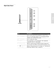
.... 2 - VOLUME + Press to adjust the volume. 4 INPUT Press repeatedly to cycle through the video equipment connected to the TV's video inputs. 5 Memory Stick When lit, indicates that the Memory Stick is lit.) 6 (Memory Memory Stick insertion slot. To scan quickly through channels. CHANNEL +... Press to turn on page 69. 17 access indicator (Do not remove the Memory Stick when the indicator is being read. Setup Right Side Panel POWER CHANNEL 1 2 VOLUME 3 INPUT 4 5 PRO 6 Item Description 1 Main POWER Press to scan through channels, press and hold down either CHANNEL...
.... 2 - VOLUME + Press to adjust the volume. 4 INPUT Press repeatedly to cycle through the video equipment connected to the TV's video inputs. 5 Memory Stick When lit, indicates that the Memory Stick is lit.) 6 (Memory Memory Stick insertion slot. To scan quickly through channels. CHANNEL +... Press to turn on page 69. 17 access indicator (Do not remove the Memory Stick when the indicator is being read. Setup Right Side Panel POWER CHANNEL 1 2 VOLUME 3 INPUT 4 5 PRO 6 Item Description 1 Main POWER Press to scan through channels, press and hold down either CHANNEL...

Operating Instructions
Page 20
Connects to the AUDIO L (MONO) jack on the TV. 18 Provides better picture quality than composite video (2). If you connect a monaural VCR or camcoder, connect the audio output to the composite A/V output jacks on your camcorder or other video equipment that has S VIDEO. Setup Left Side Panel To open the slide cover VIDEO IN 2 S VIDEO VIDEO L (MONO) R AUDIO 1 2 Item 1 S VIDEO VIDEO IN 2 2 VIDEO/ L (MONO)/R AUDIO VIDEO IN 2 Description Connects to the S VIDEO OUT jack on your camcorder or other video equipment.
Connects to the AUDIO L (MONO) jack on the TV. 18 Provides better picture quality than composite video (2). If you connect a monaural VCR or camcoder, connect the audio output to the composite A/V output jacks on your camcorder or other video equipment that has S VIDEO. Setup Left Side Panel To open the slide cover VIDEO IN 2 S VIDEO VIDEO L (MONO) R AUDIO 1 2 Item 1 S VIDEO VIDEO IN 2 2 VIDEO/ L (MONO)/R AUDIO VIDEO IN 2 Description Connects to the S VIDEO OUT jack on your camcorder or other video equipment.

Operating Instructions
Page 21
...L (MONO) VIDEO S VIDEO 5 R -AUDIO- Use this jack instead of your VCR or other Sony infrared-controlled audio or video equipment that came with your cable box input jack. A third VIDEO/ composite ...Use a DVI-D single link cable. 7 CONTROL S IN/OUT Allows the TV to receive (IN) and send (OUT) remote control signals to other video equipment that connects to ...see pages 24 and 25. 4 VIDEO IN 1/3 Connect to the composite A/V output jacks on the left side panel. These video R-AUDIO-L (MONO) connections provide better picture quality than the VHF/UHF (1) connections. 5 S VIDEO...
...L (MONO) VIDEO S VIDEO 5 R -AUDIO- Use this jack instead of your VCR or other Sony infrared-controlled audio or video equipment that came with your cable box input jack. A third VIDEO/ composite ...Use a DVI-D single link cable. 7 CONTROL S IN/OUT Allows the TV to receive (IN) and send (OUT) remote control signals to other video equipment that connects to ...see pages 24 and 25. 4 VIDEO IN 1/3 Connect to the composite A/V output jacks on the left side panel. These video R-AUDIO-L (MONO) connections provide better picture quality than the VHF/UHF (1) connections. 5 S VIDEO...

Operating Instructions
Page 22
Jack 9 WOOFER OUT (VAR) q; You can use these outputs to listen to the left and right audio input jacks of your stereo system. * High-bandwidth Digital Content Protection Setup 20 Connects to your TV's audio through your sub woofer. AUDIO OUT (VAR/FIX) L/R Description Connects to the input jack of your audio or video equipment.
Jack 9 WOOFER OUT (VAR) q; You can use these outputs to listen to the left and right audio input jacks of your stereo system. * High-bandwidth Digital Content Protection Setup 20 Connects to your TV's audio through your sub woofer. AUDIO OUT (VAR/FIX) L/R Description Connects to the input jack of your audio or video equipment.

Operating Instructions
Page 23
... pass a sturdy cord or chain and attach it to a wall or pillar. 1 Remove one of the upper two screws at the rear of the TV Attached screw Clamp screw (supplied) 2 Repeat step 1 to attach the other clamp screw. 3 Attach a sturdy cord or chain securely to each clamp screw, and attach ... optional components, do not connect the AC power cord to the screw hole. Rear of the TV, then attach the supplied clamp screw to wall outlet until you have completed making all connections. Installing the TV Connecting the AC Power Cord 1 Secure the AC power plug to a wall or pillar. 21 Be...
... pass a sturdy cord or chain and attach it to a wall or pillar. 1 Remove one of the upper two screws at the rear of the TV Attached screw Clamp screw (supplied) 2 Repeat step 1 to attach the other clamp screw. 3 Attach a sturdy cord or chain securely to each clamp screw, and attach ... optional components, do not connect the AC power cord to the screw hole. Rear of the TV, then attach the supplied clamp screw to wall outlet until you have completed making all connections. Installing the TV Connecting the AC Power Cord 1 Secure the AC power plug to a wall or pillar. 21 Be...


