
Child Safety: It Makes A Difference Where Your TV Stands
Page 1
... televisions are improperly secured or inappropriately situated on dressers, bookcases, shelves, desks, audio speakers, chests or carts. Thank you have more than one television. As a result, TV sets may cause unnecessary injury. Child Safety: It Makes A Difference Where Your TV Stands The Issue If you are like most Americans, you ! 2500 Wilson Boulevard...
... televisions are improperly secured or inappropriately situated on dressers, bookcases, shelves, desks, audio speakers, chests or carts. Thank you have more than one television. As a result, TV sets may cause unnecessary injury. Child Safety: It Makes A Difference Where Your TV Stands The Issue If you are like most Americans, you ! 2500 Wilson Boulevard...

Instructions (SU-PW3M Wall-Mount Bracket)
Page 2
.... Be sure to the TV. Specified products (As of September 2004) Flat-panel Color Television KDE-37XS955 KDE-42XS955 KDE-50XS955 When installing the TV on . If the woofer speaker joint is not damaged, and then reconnect the woofer speaker to read this manual thoroughly and use only with the following products. Sony is securely connected to the TV. (An error message will...
.... Be sure to the TV. Specified products (As of September 2004) Flat-panel Color Television KDE-37XS955 KDE-42XS955 KDE-50XS955 When installing the TV on . If the woofer speaker joint is not damaged, and then reconnect the woofer speaker to read this manual thoroughly and use only with the following products. Sony is securely connected to the TV. (An error message will...

Instructions (SU-PW3M Wall-Mount Bracket)
Page 5
...This may become exposed and cause a short circuit or an electrical break. Install the Wall-Mount Bracket For Sony Dealers WARNING To Sony Dealers The following the instructions in the speaker unit which generates magnetic influence. Be sure to 75ohm coaxial cables. Be sure to install the Wall-Mount ... above and pay special attention to safety during the installation, maintenance and checking of the screws are susceptible to read safety precautions described above the TV may cause a fire or an electric shock. 5 (US) If it on the Wall-Mount Bracket for a long time, the wall behind...
...This may become exposed and cause a short circuit or an electrical break. Install the Wall-Mount Bracket For Sony Dealers WARNING To Sony Dealers The following the instructions in the speaker unit which generates magnetic influence. Be sure to 75ohm coaxial cables. Be sure to install the Wall-Mount ... above and pay special attention to safety during the installation, maintenance and checking of the screws are susceptible to read safety precautions described above the TV may cause a fire or an electric shock. 5 (US) If it on the Wall-Mount Bracket for a long time, the wall behind...

Instructions (SU-PW3M Wall-Mount Bracket)
Page 7
...× L20) (4) Screw (+PSW5 × L14) (6) 7 (US) The position for suitable clearance between the TV and the ceiling and protruding parts of the wall, beforehand. 2 Open the package and check the parts. Unit: ...mm (inches) 300 (11 13⁄16) Plate Unit (1) Woofer Speaker 100 (3 15⁄16) Hook (4) 100 (3 15⁄16) 100 (3 15⁄16) Mounting Rack... Decide on the installation location 1 Place the paper template on a perpendicular, flat wall and decide on page 17. Allow for the cable hole is printed on the paper template ...
...× L20) (4) Screw (+PSW5 × L14) (6) 7 (US) The position for suitable clearance between the TV and the ceiling and protruding parts of the wall, beforehand. 2 Open the package and check the parts. Unit: ...mm (inches) 300 (11 13⁄16) Plate Unit (1) Woofer Speaker 100 (3 15⁄16) Hook (4) 100 (3 15⁄16) 100 (3 15⁄16) Mounting Rack... Decide on the installation location 1 Place the paper template on a perpendicular, flat wall and decide on page 17. Allow for the cable hole is printed on the paper template ...
Instructions (SU-PW3M Wall-Mount Bracket)
Page 10
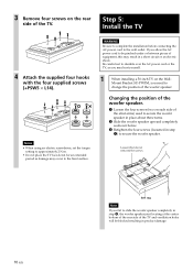
... locating at the center bottom of the rear side of the TV and ventilation holes will be pinched under or between pieces of equipment, this may hurt yourself. 1 When installing a 50-inch TV on the rear side of the woofer speaker. Notes • When using an electric screwdriver, set the torque... setting to approximately 2 N·m. • Do not place the TV face down for an extended period as you need to the ...
... locating at the center bottom of the rear side of the TV and ventilation holes will be pinched under or between pieces of equipment, this may hurt yourself. 1 When installing a 50-inch TV on the rear side of the woofer speaker. Notes • When using an electric screwdriver, set the torque... setting to approximately 2 N·m. • Do not place the TV face down for an extended period as you need to the ...
Instructions (SU-PW3M Wall-Mount Bracket)
Page 11
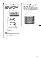
... routing 11 (US) When sliding the Mounting Rack, make sure that the woofer speaker is located on the rear side of the TV. Woofer speaker joint 3 Connect the AC power cord and the connecting cable(s) supplied with the TV to the TV. When you route the cable and the cord in the wall, feed them... bored (page 17). 2 Hitch the Mounting Rack on the hooks on the lower right part of the Mounting Rack. Soft rag Rear side of the TV Note The woofer speaker joint is securely connected to the TV. Then slide the Mounting Rack and fix it using the supplied screws (+PSW5 × L14).
... routing 11 (US) When sliding the Mounting Rack, make sure that the woofer speaker is located on the rear side of the TV. Woofer speaker joint 3 Connect the AC power cord and the connecting cable(s) supplied with the TV to the TV. When you route the cable and the cord in the wall, feed them... bored (page 17). 2 Hitch the Mounting Rack on the hooks on the lower right part of the Mounting Rack. Soft rag Rear side of the TV Note The woofer speaker joint is securely connected to the TV. Then slide the Mounting Rack and fix it using the supplied screws (+PSW5 × L14).
Instructions (SU-PW3M Wall-Mount Bracket)
Page 13
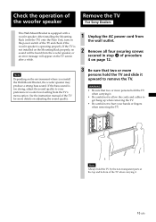
...not to allow the cords and cables to get hung up when removing the TV. • Be careful not to your hands or fingers when removing the TV. Check the operation of the woofer speaker Remove the TV For Sony Dealers This Wall-Mount Bracket is operating properly. Note Depending on adjusting the ...sound quality. 3 Be sure that two or more persons hold the TV and slide it . 13 (US) If ...
...not to allow the cords and cables to get hung up when removing the TV. • Be careful not to your hands or fingers when removing the TV. Check the operation of the woofer speaker Remove the TV For Sony Dealers This Wall-Mount Bracket is operating properly. Note Depending on adjusting the ...sound quality. 3 Be sure that two or more persons hold the TV and slide it . 13 (US) If ...

Instructions (SU-PW3M Wall-Mount Bracket)
Page 15
power 10 cm (2) 4 Ω 50 W 420 (16 17⁄32) 480 (18 29⁄32) 15 (US) PLATE UNIT 79 (3 1⁄8) ø 90 (3 5⁄8) 670 (26 3⁄8) MOUNTING RACK 505 (19 29⁄32)* 520 (20 1⁄2) 44 85.5 (1 3⁄4) (3 3⁄8) * When changing the position of the woofer speaker for installing a 50-inch TV: 590 (23 1/4) SPEAKER Speaker unit Impedance Max. Specifications Unit: mm (inches) Weight: 15.0 kg (33 lb 1 oz) Design and specifications are subject to change without notice.
power 10 cm (2) 4 Ω 50 W 420 (16 17⁄32) 480 (18 29⁄32) 15 (US) PLATE UNIT 79 (3 1⁄8) ø 90 (3 5⁄8) 670 (26 3⁄8) MOUNTING RACK 505 (19 29⁄32)* 520 (20 1⁄2) 44 85.5 (1 3⁄4) (3 3⁄8) * When changing the position of the woofer speaker for installing a 50-inch TV: 590 (23 1/4) SPEAKER Speaker unit Impedance Max. Specifications Unit: mm (inches) Weight: 15.0 kg (33 lb 1 oz) Design and specifications are subject to change without notice.
Operating Instructions
Page 9
... 11 Package Contents 11 Features 12 Overview 15 TV Controls and Connectors 16 Front panel 16 Side panel 17 Rear panel 18 Connecting the Power Cord 20 Preventing the TV from Toppling Over 21 Bundling the Connecting Cables 22 Basic Connections: Connecting a Cable or Antenna 23 Cable or...DVD Player or Digital Satellite Receiver via AV Receiver with CENTER SPEAKER IN Terminals 46 Camcorder 48 Audio Receiver 49 Sub Woofer 49 Device with an Optical (Digital Audio) Connector 50 Using the CONTROL S Feature 50 Using CableCARD 51 Activating CableCARD™ Service 51 Removing the ...
... 11 Package Contents 11 Features 12 Overview 15 TV Controls and Connectors 16 Front panel 16 Side panel 17 Rear panel 18 Connecting the Power Cord 20 Preventing the TV from Toppling Over 21 Bundling the Connecting Cables 22 Basic Connections: Connecting a Cable or Antenna 23 Cable or...DVD Player or Digital Satellite Receiver via AV Receiver with CENTER SPEAKER IN Terminals 46 Camcorder 48 Audio Receiver 49 Sub Woofer 49 Device with an Optical (Digital Audio) Connector 50 Using the CONTROL S Feature 50 Using CableCARD 51 Activating CableCARD™ Service 51 Removing the ...
Operating Instructions
Page 17
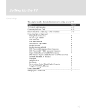
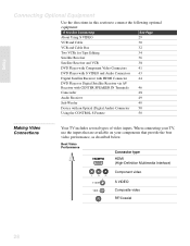
...Connecting Optional Equipment Making Video Connections About Using S VIDEO VCR and Cable VCR and Cable Box Two VCRs for setting up your TV. Setting Up the TV Overview This chapter includes illustrated instructions for Tape Editing Satellite Receiver Satellite Receiver and VCR DVD Player with Component Video Connectors DVD Player... SPEAKER IN Terminals Camcorder Audio Receiver Sub Woofer Device with an Optical (Digital Audio) Connector Using the CONTROL S Feature Using CableCARD™ Setting Up the Channel List Page(s) 16-19 20-22 23-27 28 29 30 32 34 36 38 41 43 44 46 48 49 49 50 50 ...
...Connecting Optional Equipment Making Video Connections About Using S VIDEO VCR and Cable VCR and Cable Box Two VCRs for setting up your TV. Setting Up the TV Overview This chapter includes illustrated instructions for Tape Editing Satellite Receiver Satellite Receiver and VCR DVD Player with Component Video Connectors DVD Player... SPEAKER IN Terminals Camcorder Audio Receiver Sub Woofer Device with an Optical (Digital Audio) Connector Using the CONTROL S Feature Using CableCARD™ Setting Up the Channel List Page(s) 16-19 20-22 23-27 28 29 30 32 34 36 38 41 43 44 46 48 49 49 50 50 ...
Operating Instructions
Page 18
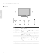
... 111). The LED does not light up when the main power is turned off . If the LED blinks in red. TV Controls and Connectors Front panel Setup PICTURE OFF TIMER STANDBY POWER Item 1 Speakers (Left/Right) 2 PICTURE OFF LED 3 TIMER LED 4 STANDBY LED 5 POWER LED 6 (IR) Infrared Receiver Description ... . Lights up in red continuously, this LED will remain lit even if the TV set is set is activated. When the timer is set, this may indicate the display unit needs servicing (see "Contacting Sony" on . Receives IR signals from the remote control. 16 For details, see page 107...
... 111). The LED does not light up when the main power is turned off . If the LED blinks in red. TV Controls and Connectors Front panel Setup PICTURE OFF TIMER STANDBY POWER Item 1 Speakers (Left/Right) 2 PICTURE OFF LED 3 TIMER LED 4 STANDBY LED 5 POWER LED 6 (IR) Infrared Receiver Description ... . Lights up in red continuously, this LED will remain lit even if the TV set is set is activated. When the timer is set, this may indicate the display unit needs servicing (see "Contacting Sony" on . Receives IR signals from the remote control. 16 For details, see page 107...
Operating Instructions
Page 20
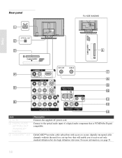
... cable channels-without the need for a set-top-box-that is PCM/Dolby Digital compatible. Rear panel AC IN OPTICAL OUT For KDE-50XS955 Setup CableCARD CableCARD R-AUDIO -L VIDEO IN VHF/UHF 6 CABLE 1 3 R-AUDIO -L (MONO) VIDEO S VIDEO 4 CENTER SPEAKER IN 180W (6 ) MAX CONTROL S IN OUT 5 R-AUDIO -L Y PB PR HD/DVD IN (1080i/720p/480p...
... cable channels-without the need for a set-top-box-that is PCM/Dolby Digital compatible. Rear panel AC IN OPTICAL OUT For KDE-50XS955 Setup CableCARD CableCARD R-AUDIO -L VIDEO IN VHF/UHF 6 CABLE 1 3 R-AUDIO -L (MONO) VIDEO S VIDEO 4 CENTER SPEAKER IN 180W (6 ) MAX CONTROL S IN OUT 5 R-AUDIO -L Y PB PR HD/DVD IN (1080i/720p/480p...

Operating Instructions
Page 21
...VHF/UHF antenna or cable box. 9 VIDEO 1/3 IN S VIDEO Connects to the left side panel of your VCR or other video equipment that has the CONTROL S function. HDMI supports enhanced,...provides an uncompressed, all-digital HDMI IN/R-AUDIO-L audio/video interface between this TV and any HDMI-equipped audio/video component, such as a center speaker. R-AUDIO-L (MONO) 6 HD/DVD 4/5 IN (1080i/720p/480p/ ... other Sony infrared-controlled audio or video equipment that has S VIDEO. qa CONTROL S IN/OUT Allows the TV to receive (IN) and send (OUT) remote control signals to your TV's audio...
...VHF/UHF antenna or cable box. 9 VIDEO 1/3 IN S VIDEO Connects to the left side panel of your VCR or other video equipment that has the CONTROL S function. HDMI supports enhanced,...provides an uncompressed, all-digital HDMI IN/R-AUDIO-L audio/video interface between this TV and any HDMI-equipped audio/video component, such as a center speaker. R-AUDIO-L (MONO) 6 HD/DVD 4/5 IN (1080i/720p/480p/ ... other Sony infrared-controlled audio or video equipment that has S VIDEO. qa CONTROL S IN/OUT Allows the TV to receive (IN) and send (OUT) remote control signals to your TV's audio...
Operating Instructions
Page 30
... Performance Connector type HDMI (High-Definition Multimedia Interface) Y PB PR Component video S VIDEO Composite video RF/Coaxial 28 When connecting your TV, use the inputs that are available on your components that provide the best video performance, as described below. Setup Connecting Optional Equipment Use... and Audio Connectors 43 Digital Satellite Receiver with HDMI Connector 44 DVD Player or Digital Satellite Receiver via AV Receiver with CENTER SPEAKER IN Terminals 46 Camcorder 48 Audio Receiver 49 Sub Woofer 49 Device with an Optical (Digital Audio) Connector...
... Performance Connector type HDMI (High-Definition Multimedia Interface) Y PB PR Component video S VIDEO Composite video RF/Coaxial 28 When connecting your TV, use the inputs that are available on your components that provide the best video performance, as described below. Setup Connecting Optional Equipment Use... and Audio Connectors 43 Digital Satellite Receiver with HDMI Connector 44 DVD Player or Digital Satellite Receiver via AV Receiver with CENTER SPEAKER IN Terminals 46 Camcorder 48 Audio Receiver 49 Sub Woofer 49 Device with an Optical (Digital Audio) Connector...
Operating Instructions
Page 48
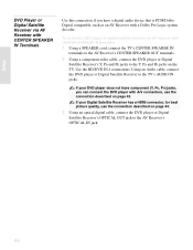
... the connection described on page 43. Setup DVD Player or Digital Satellite Receiver via AV receiver with CENTER SPEAKER IN terminals 1 Using a SPEAKER cord, connect the TV's CENTER SPEAKER IN terminals to the AV Receiver's CENTER SPEAKER OUT terminals. 2 Using a component video cable, connect the DVD player or Digital Satellite Receiver's Y, PB and PR jacks...
... the connection described on page 43. Setup DVD Player or Digital Satellite Receiver via AV receiver with CENTER SPEAKER IN terminals 1 Using a SPEAKER cord, connect the TV's CENTER SPEAKER IN terminals to the AV Receiver's CENTER SPEAKER OUT terminals. 2 Using a component video cable, connect the DVD player or Digital Satellite Receiver's Y, PB and PR jacks...

Operating Instructions
Page 49
Setup Rear of TV 4 5 R-AUDIO -L Y PB PR HD/DVD IN (1080i/720p/480p/480i) Audio cable Component video cable CENTER SPEAKER IN 180W (6 ) MAX SPEAKER cord DVD Player or Digital Satellite Receiver FRONT R CENTER FRONT L SURR R SURR L SUB WOOFER AUDIO OUT SPEAKER SCAN SELECT SELECTABLE R INTERLACE COMPONENT VIDEO OUT R VIDEO 1 ... PR/CR COMPONENT VIDEO OUT OPTICAL DIGITAL IN VIDEO 2 AV Receiver AM FM 75 COAXIAL Optical digital cable When using the TV's speakers as the center speaker Using Center Speaker In in the AUDIO menu, select the video input for which you want to use the...
Setup Rear of TV 4 5 R-AUDIO -L Y PB PR HD/DVD IN (1080i/720p/480p/480i) Audio cable Component video cable CENTER SPEAKER IN 180W (6 ) MAX SPEAKER cord DVD Player or Digital Satellite Receiver FRONT R CENTER FRONT L SURR R SURR L SUB WOOFER AUDIO OUT SPEAKER SCAN SELECT SELECTABLE R INTERLACE COMPONENT VIDEO OUT R VIDEO 1 ... PR/CR COMPONENT VIDEO OUT OPTICAL DIGITAL IN VIDEO 2 AV Receiver AM FM 75 COAXIAL Optical digital cable When using the TV's speakers as the center speaker Using Center Speaker In in the AUDIO menu, select the video input for which you want to use the...

Operating Instructions
Page 51
... option to Fixed or Variable, depending on the audio receiver, and then set the Speaker option to Off. Use a monaural audio cable to connect the TV's SUBWOOFER OUT jack to the audio receiver's line input jacks. Rear of TV R-AUDIO -L AUDIO OUT (VAR/FIX) Sub Woofer Audio cable Audio Receiver To line ... Sub Woofer 49 For details, see "Using the Audio Menu" on page 95. 3 Turn on how you connected the TV. To connect an audio system 1 Use an audio cable to connect the TV's AUDIO OUT jacks to the sub woofer's input jack. Setup Audio Receiver For improved sound quality, you may want...
... option to Fixed or Variable, depending on the audio receiver, and then set the Speaker option to Off. Use a monaural audio cable to connect the TV's SUBWOOFER OUT jack to the audio receiver's line input jacks. Rear of TV R-AUDIO -L AUDIO OUT (VAR/FIX) Sub Woofer Audio cable Audio Receiver To line ... Sub Woofer 49 For details, see "Using the Audio Menu" on page 95. 3 Turn on how you connected the TV. To connect an audio system 1 Use an audio cable to connect the TV's AUDIO OUT jacks to the sub woofer's input jack. Setup Audio Receiver For improved sound quality, you may want...
Operating Instructions
Page 97
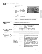
...programs Description Dynamic Select to exit the Menu. Adjust to emphasize left or right speaker balance. Adjust to decrease or increase higher-pitched sounds. Simulated Adds a surround...Audio Options z Treble and Bass are not available when Dynamic or Clear Voice is received. Custom Flat setting. Off Select to change settings. Mono Select for stereo programs only). Clear Voice Suitable for...Press RESET on the remote control when in stereo. Auto SAP Select to automatically switch the TV to stabilize the volume. Menus Using the Audio Menu To select the Audio menu 1 ...
...programs Description Dynamic Select to exit the Menu. Adjust to emphasize left or right speaker balance. Adjust to decrease or increase higher-pitched sounds. Simulated Adds a surround...Audio Options z Treble and Bass are not available when Dynamic or Clear Voice is received. Custom Flat setting. Off Select to change settings. Mono Select for stereo programs only). Clear Voice Suitable for...Press RESET on the remote control when in stereo. Auto SAP Select to automatically switch the TV to stabilize the volume. Menus Using the Audio Menu To select the Audio menu 1 ...

Operating Instructions
Page 98
... to adjust the volume (and other audio settings) through your audio system. Menus Option Description Center Speaker Select the video input (TV, Video 1-6) you want to use the TV's In speakers as the center speaker) sounds unnatural. Variable The TV's speakers are turned off the TV speakers and listen to the TV's sound only through your external audio receiver and...
... to adjust the volume (and other audio settings) through your audio system. Menus Option Description Center Speaker Select the video input (TV, Video 1-6) you want to use the TV's In speakers as the center speaker) sounds unnatural. Variable The TV's speakers are turned off the TV speakers and listen to the TV's sound only through your external audio receiver and...
Operating Instructions
Page 116
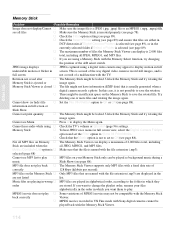
... print quantity s The Memory Stick might be locked. s Check the Filter option setting (see page 88). s Check that files are using s Check the TV's volume or Speaker (page 96) settings. s Check the Select Folder setting (see MP3 list to play s MP3 files on the Memory Stick to On or Off (see... page 88). This is a result of a malfunction with Sony digital cameras cannot be played as background music during a music Slide Show (see page 88). ...
... print quantity s The Memory Stick might be locked. s Check the Filter option setting (see page 88). s Check that files are using s Check the TV's volume or Speaker (page 96) settings. s Check the Select Folder setting (see MP3 list to play s MP3 files on the Memory Stick to On or Off (see... page 88). This is a result of a malfunction with Sony digital cameras cannot be played as background music during a music Slide Show (see page 88). ...

