
Operating Instructions (Receiver)
Page 1
4-227-987-13(1) FM Stereo FM-AM Receiver Operating Instructions STR-DE545 STR-DE445 STR-SE501 © 2000 Sony Corporation
4-227-987-13(1) FM Stereo FM-AM Receiver Operating Instructions STR-DE545 STR-DE445 STR-SE501 © 2000 Sony Corporation
Operating Instructions (Receiver)
Page 2
... you have it is intended to alert the user to radio communications. If this equipment. Increase the separation between the equipment and receiver. - WARNING Precautions To prevent fire or shock hazard, do not expose the unit to constitute a risk of important operating and maintenance... at the qualified service shop. On safety Should any question or problem concerning your receiver, please consult your local power supply. As an ENERGY STAR® partner, Sony Corporation has determined that interference will fit into the outlet, contact your authority to ...
... you have it is intended to alert the user to radio communications. If this equipment. Increase the separation between the equipment and receiver. - WARNING Precautions To prevent fire or shock hazard, do not expose the unit to constitute a risk of important operating and maintenance... at the qualified service shop. On safety Should any question or problem concerning your receiver, please consult your local power supply. As an ENERGY STAR® partner, Sony Corporation has determined that interference will fit into the outlet, contact your authority to ...
Operating Instructions (Receiver)
Page 3
... or lower right corner of Digital Theater Systems, Inc. © 1996 Digital Theater Systems, Inc. No. 5,451,942 and other worldwide patents issued and pending. Demonstration Mode The demonstration will activate the first time you turn the receiver off while the above message is ...Speaker System Hookup 13 Performing Initial Setup Operations 15 Multi Channel Surround Setup 16 Before You Use Your Receiver 20 Location of Dolby Laboratories. **Manufactured under license from Digital Theater Systems, Inc. About This Manual The instructions in the text, for example, "STR-DE545 only...
... or lower right corner of Digital Theater Systems, Inc. © 1996 Digital Theater Systems, Inc. No. 5,451,942 and other worldwide patents issued and pending. Demonstration Mode The demonstration will activate the first time you turn the receiver off while the above message is ...Speaker System Hookup 13 Performing Initial Setup Operations 15 Multi Channel Surround Setup 16 Before You Use Your Receiver 20 Location of Dolby Laboratories. **Manufactured under license from Digital Theater Systems, Inc. About This Manual The instructions in the text, for example, "STR-DE545 only...
Operating Instructions (Receiver)
Page 4
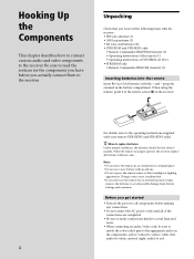
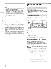
... remote sensor to the operating instructions supplied with your remote (STR-DE545 and STR-SE501 only). white (left, audio) to the receiver. Before you received the following items with the receiver: • FM wire antenna (1) • AM loop antenna (1) • R6 (size-AA) batteries (2) • STR-...components to white; Notes • Do not leave the remote in the battery compartment. When the remote no longer operates the receiver, replace all of time, remove the batteries to replace batteries Under normal conditions, the batteries should last for the components you have...
... remote sensor to the operating instructions supplied with your remote (STR-DE545 and STR-SE501 only). white (left, audio) to the receiver. Before you received the following items with the receiver: • FM wire antenna (1) • AM loop antenna (1) • R6 (size-AA) batteries (2) • STR-...components to white; Notes • Do not leave the remote in the battery compartment. When the remote no longer operates the receiver, replace all of time, remove the batteries to replace batteries Under normal conditions, the batteries should last for the components you have...

Operating Instructions (Receiver)
Page 5
... ANTENNA Ground wire (not supplied) To ground Important If you have poor FM reception Use a 75-ohm coaxial cable (not supplied) to connect the receiver to an outdoor FM antenna as possible. Hooking Up the Components Antenna Hookups AM loop antenna (supplied) FM wire antenna (supplied) FM 75Ω ...AM terminals FM 75Ω COAXIAL terminal Notes on antenna hookups • To prevent noise pickup, keep the AM loop antenna away from the receiver and other components. • Be sure to fully extend the FM wire antenna. • After connecting the FM wire antenna, keep it against ...
... ANTENNA Ground wire (not supplied) To ground Important If you have poor FM reception Use a 75-ohm coaxial cable (not supplied) to connect the receiver to an outdoor FM antenna as possible. Hooking Up the Components Antenna Hookups AM loop antenna (supplied) FM wire antenna (supplied) FM 75Ω ...AM terminals FM 75Ω COAXIAL terminal Notes on antenna hookups • To prevent noise pickup, keep the AM loop antenna away from the receiver and other components. • Be sure to fully extend the FM wire antenna. • After connecting the FM wire antenna, keep it against ...
Operating Instructions (Receiver)
Page 7
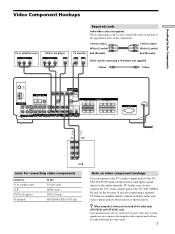
... Note on video component hookups You can connect your TV's audio output jacks to the TV/ SAT AUDIO IN jacks on the receiver and apply sound effects to the receiver as shown above. In this case, do not connect the TV's video output jack to the appropriate jacks on the components. z When... Audio/video cords (not supplied) When connecting a cord, be sure to match the color-coded pins to the TV/SAT VIDEO IN jack on the receiver. S-video signals are connecting a separate TV tuner (or satellite tuner), connect both the audio and video output jacks to the audio from the video signals...
... Note on video component hookups You can connect your TV's audio output jacks to the TV/ SAT AUDIO IN jacks on the receiver and apply sound effects to the receiver as shown above. In this case, do not connect the TV's video output jack to the appropriate jacks on the components. z When... Audio/video cords (not supplied) When connecting a cord, be sure to match the color-coded pins to the TV/SAT VIDEO IN jack on the receiver. S-video signals are connecting a separate TV tuner (or satellite tuner), connect both the audio and video output jacks to the audio from the video signals...
Operating Instructions (Receiver)
Page 8
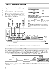
...TV/SAT DVD/LD ** MONITOR CTRL A1 I I - Refer to the instruction manual supplied with your home. D. 2CH MODE I VIDEO IN VIDEO IN VIDEO OUT VIDEO IN VIDEO OUT ANTENNA L OPTICAL OPTICAL...L R L R L R L AC OUTLET SWITCHED 120W/1A MAX AC 120V 60Hz * When making connections as the Sony MOD-RF1 (not supplied). TUNING + MEMORY FM/AM FM MODE MUTING BASS BOOST TONE Note When making digital audio connections...player and satellite tuner (etc.) to the receiver's digital input jacks to bring the multi channel surround sound of a movie theater into your RF Demodulator for details on ...
...TV/SAT DVD/LD ** MONITOR CTRL A1 I I - Refer to the instruction manual supplied with your home. D. 2CH MODE I VIDEO IN VIDEO IN VIDEO OUT VIDEO IN VIDEO OUT ANTENNA L OPTICAL OPTICAL...L R L R L R L AC OUTLET SWITCHED 120W/1A MAX AC 120V 60Hz * When making connections as the Sony MOD-RF1 (not supplied). TUNING + MEMORY FM/AM FM MODE MUTING BASS BOOST TONE Note When making digital audio connections...player and satellite tuner (etc.) to the receiver's digital input jacks to bring the multi channel surround sound of a movie theater into your RF Demodulator for details on ...

Operating Instructions (Receiver)
Page 9
... + SET UP NAME ENTER BASS BOOST TONE MASTER VOLUME PRESET - TUNING + SHIFT - Hooking Up the Components 5.1CH Input Hookups Although this receiver incorporates a multi channel decoder, it is also equipped with 5.1CH OUTPUT jacks, you can be used to the instruction manual supplied with your ...multi channel decoder, etc., for details on speaker system hookup. F. Alternatively, the 5.1CH INPUT jacks can connect them directly to the receiver to enjoy multichannel software encoded in formats other than Dolby Digital (AC-3) and DTS. FM 75Ω COAXIAL AM DIGITAL IN TV/...
... + SET UP NAME ENTER BASS BOOST TONE MASTER VOLUME PRESET - TUNING + SHIFT - Hooking Up the Components 5.1CH Input Hookups Although this receiver incorporates a multi channel decoder, it is also equipped with 5.1CH OUTPUT jacks, you can be used to the instruction manual supplied with your ...multi channel decoder, etc., for details on speaker system hookup. F. Alternatively, the 5.1CH INPUT jacks can connect them directly to the receiver to enjoy multichannel software encoded in formats other than Dolby Digital (AC-3) and DTS. FM 75Ω COAXIAL AM DIGITAL IN TV/...
Operating Instructions (Receiver)
Page 11
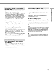
...cleared and the demonstration will supply power to the connected component(s), allowing you to turn the receiver on the receiver. This may cause a malfunction. • If you have a Sony CD changer with your CD changer's COMMAND MODE selector can listen to stereo sources in surround... sound. STR-DE545 and STR-SE501 only If you connect other audio/video components to the AC OUTLET(s) on the receiver, the receiver will start. 11 Do not connect high-wattage electrical home...
...cleared and the demonstration will supply power to the connected component(s), allowing you to turn the receiver on the receiver. This may cause a malfunction. • If you have a Sony CD changer with your CD changer's COMMAND MODE selector can listen to stereo sources in surround... sound. STR-DE545 and STR-SE501 only If you connect other audio/video components to the AC OUTLET(s) on the receiver, the receiver will start. 11 Do not connect high-wattage electrical home...
Operating Instructions (Receiver)
Page 12
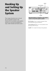
... up the speaker system SET UP button: Press to adjust the setting of each speaker, and how to set up your speaker system to the receiver, how to position each parameter. 12 Jog dial: Use to enter the setup mode when specifying speaker types and distances. TUNING + SHIFT - Cursor buttons ( / ): Use...
... up the speaker system SET UP button: Press to adjust the setting of each speaker, and how to set up your speaker system to the receiver, how to position each parameter. 12 Jog dial: Use to enter the setup mode when specifying speaker types and distances. TUNING + SHIFT - Cursor buttons ( / ): Use...
Operating Instructions (Receiver)
Page 13
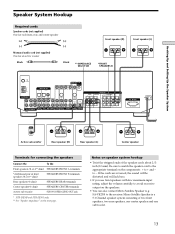
...) SPEAKERS CENTER terminals Active sub woofer SUB WOOFER AUDIO OUT jack * STR-DE545 and STR-SE501 only. ** See "Speaker impedance" on the components: + to the receiver. Be sure to match the speaker cord to the appropriate terminal on the next page. SA-VE230) to + and - ] Hooking Up and Setting Up the...
...) SPEAKERS CENTER terminals Active sub woofer SUB WOOFER AUDIO OUT jack * STR-DE545 and STR-SE501 only. ** See "Speaker impedance" on the components: + to the receiver. Be sure to match the speaker cord to the appropriate terminal on the next page. SA-VE230) to + and - ] Hooking Up and Setting Up the...
Operating Instructions (Receiver)
Page 14
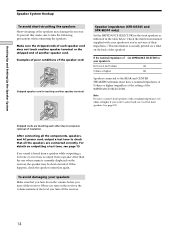
...speakers if you're not sure of their impedance. (This information is usually printed on a label on the receiver, the volume remains at the level you turn off the receiver. After connecting all the components, speakers, and AC power cord, output a test tone to the REAR ... 8 ohms or higher 8Ω Speakers connected to check that you turn down the volume before you turn off the receiver. 14 For details on the receiver, the speaker may damage the receiver. If this , make sure to select both sets (A+B) of insulation. Check the instruction manual supplied with a nominal ...
...speakers if you're not sure of their impedance. (This information is usually printed on a label on the receiver, the volume remains at the level you turn off the receiver. After connecting all the components, speakers, and AC power cord, output a test tone to the REAR ... 8 ohms or higher 8Ω Speakers connected to check that you turn down the volume before you turn off the receiver. 14 For details on the receiver, the speaker may damage the receiver. If this , make sure to select both sets (A+B) of insulation. Check the instruction manual supplied with a nominal ...

Operating Instructions (Receiver)
Page 15
... for your system. TUNING + SHIFT - Before turning on how to adjust each program source and preset stations are reset to clear the receiver's memory, do the following. The currently selected function, then the demonstration message appears in parentheses. • Speaker size and placement (page... position, etc.) and perform any other initial setup operations necessary for each setting, see "7 SPEAKERS selector" on the power, clear the receiver's memory. You can set the following are reset or cleared: • All preset stations are reset or cleared. • All sound ...
... for your system. TUNING + SHIFT - Before turning on how to adjust each program source and preset stations are reset to clear the receiver's memory, do the following. The currently selected function, then the demonstration message appears in parentheses. • Speaker size and placement (page... position, etc.) and perform any other initial setup operations necessary for each setting, see "7 SPEAKERS selector" on the power, clear the receiver's memory. You can set the following are reset or cleared: • All preset stations are reset or cleared. • All sound ...
Operating Instructions (Receiver)
Page 16
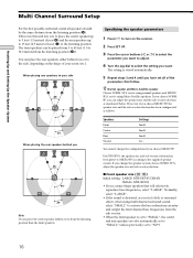
... sound all of your side B A A 45° C C 90° 20° When placing the rear speakers behind you or to the side, depending on the receiver. 2 Press SET UP. 3 Press the cursor buttons ( or ) to select the parameter you want to adjust. 4 Turn the jog dial to select the setting you...
... sound all of your side B A A 45° C C 90° 20° When placing the rear speakers behind you or to the side, depending on the receiver. 2 Press SET UP. 3 Press the cursor buttons ( or ) to select the parameter you want to adjust. 4 Turn the jog dial to select the setting you...
Operating Instructions (Receiver)
Page 19
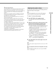
...farther away than the front speakers. In other words, the speaker will cause a delay in the output of being "inside" the screen. Note This receiver incorporates a new test tone with a frequency centered at the same time Rotate MASTER VOLUME on the remote. 19 Use +/- Note The test tone cannot...sequence. 3 Adjust the volume level so that 5 feet (1.5 meters) closer than the front speakers. Also, the center speaker can be output when the receiver is not possible to input the speaker position in terms of the test tone from each speaker. Give it a try! You will create a larger ...
...farther away than the front speakers. In other words, the speaker will cause a delay in the output of being "inside" the screen. Note This receiver incorporates a new test tone with a frequency centered at the same time Rotate MASTER VOLUME on the remote. 19 Use +/- Note The test tone cannot...sequence. 3 Adjust the volume level so that 5 feet (1.5 meters) closer than the front speakers. Also, the center speaker can be output when the receiver is not possible to input the speaker position in terms of the test tone from each speaker. Give it a try! You will create a larger ...
Operating Instructions (Receiver)
Page 20
...produce better results. z When setting the volume levels for the reason in the character of the soundstage. This is output, the receiver switches to the LEVEL menu automatically), we recommend you follow the procedure previously described in order to create a more cohesive soundstage with ...turning the MASTER VOLUME. , Check that you have : • Selected the appropriate front speakers (see "7 SPEAKERS selector" on the receiver Make sure that the SPEAKERS selector is likely to playback of your software. Although this section and adjust the speaker levels from your listening...
...produce better results. z When setting the volume levels for the reason in the character of the soundstage. This is output, the receiver switches to the LEVEL menu automatically), we recommend you follow the procedure previously described in order to create a more cohesive soundstage with ...turning the MASTER VOLUME. , Check that you have : • Selected the appropriate front speakers (see "7 SPEAKERS selector" on the receiver Make sure that the SPEAKERS selector is likely to playback of your software. Although this section and adjust the speaker levels from your listening...

Operating Instructions (Receiver)
Page 21
... the component is connected correctly to the audio input jacks for the connection is output from the headphones (see "Troubleshooting" on both the receiver and the component. Check the connection of headphones to the PHONES jack and set the SPEAKERS selector to OFF to verify that the cord(s)...front speakers. , Connect a pair of the front speaker which is not included above, see "7 SPEAKERS selector" and "PHONES jack" on both the receiver and the component. Check that is not outputting any sound. If you encounter a problem that all the cords are ) fully inserted into the jacks...
... the component is connected correctly to the audio input jacks for the connection is output from the headphones (see "Troubleshooting" on both the receiver and the component. Check the connection of headphones to the PHONES jack and set the SPEAKERS selector to OFF to verify that the cord(s)...front speakers. , Connect a pair of the front speaker which is not included above, see "7 SPEAKERS selector" and "PHONES jack" on both the receiver and the component. Check that is not outputting any sound. If you encounter a problem that all the cords are ) fully inserted into the jacks...
Operating Instructions (Receiver)
Page 22
... selecting the component, turn on the component you selected and play the program source. • After selecting VCR, DVD player, or LD player, turn the receiver on and off. 2 Function buttons Press one of the buttons and controls on the TV and set the TV's video input to use. Front Panel...
... selecting the component, turn on the component you selected and play the program source. • After selecting VCR, DVD player, or LD player, turn the receiver on and off. 2 Function buttons Press one of the buttons and controls on the TV and set the TV's video input to use. Front Panel...

Operating Instructions (Receiver)
Page 24
... signal being input and perform proper decoding (if necessary). 2CH button / indicator Press to output sound from page 27. button / indicator Press to set the receiver to automatically detect the type of the component or the preset station* v FUNCTION button indication or frequency** v Sound field applied to change the information on...
... signal being input and perform proper decoding (if necessary). 2CH button / indicator Press to output sound from page 27. button / indicator Press to set the receiver to automatically detect the type of the component or the preset station* v FUNCTION button indication or frequency** v Sound field applied to change the information on...
Operating Instructions (Receiver)
Page 25
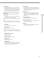
...TONE button Press to turn off the TONE indicator. Note that is poor, press this button to the program source. For details, see "Receiving Broadcasts" starting from page 37. The indicator on the button lights up and you turn on the tone effect. qh The following buttons ...level, surround, and bass/treble parameters (etc.). 25 wa Jog dial Turn to activate the surround parameters (page 33). For details, see "Receiving Broadcasts" starting from page 37. The indicator on the button lights up and you want to listen to an analog source without any digital processing...
...TONE button Press to turn off the TONE indicator. Note that is poor, press this button to the program source. For details, see "Receiving Broadcasts" starting from page 37. The indicator on the button lights up and you turn on the tone effect. qh The following buttons ...level, surround, and bass/treble parameters (etc.). 25 wa Jog dial Turn to activate the surround parameters (page 33). For details, see "Receiving Broadcasts" starting from page 37. The indicator on the button lights up and you want to listen to an analog source without any digital processing...


