

Child Safety: It Makes A Difference Where Your TV Stands
Page 1
...Sponsor, Producer and Manager of the International CES® and is committed to making home entertainment enjoyable and safe. Many homes, in your home. The Consumer Electronics Association formed the Home Entertainment Support Safety Committee comprised of the Electronic Industries Alliance As a result, TV...become excited while watching a program and can potentially push or pull a TV over and may cause unnecessary injury. The home theater entertainment experience is large enough to support the weight of your television (and other electronic components). 2 Use appropriate angle ...
...Sponsor, Producer and Manager of the International CES® and is committed to making home entertainment enjoyable and safe. Many homes, in your home. The Consumer Electronics Association formed the Home Entertainment Support Safety Committee comprised of the Electronic Industries Alliance As a result, TV...become excited while watching a program and can potentially push or pull a TV over and may cause unnecessary injury. The home theater entertainment experience is large enough to support the weight of your television (and other electronic components). 2 Use appropriate angle ...

Limited Warranty (US Only)
Page 1
...warranty service, you , or for service assistance or resolution of a service problem, or for product information or operation, call : 1-800-488-SONY (7669) Printed in Japan 4-557-172-02 General Stereo/Hifi Components/Tape Decks ® CD Players/Mini Disc Players/Audio Systems Hifi Audio ...warranty does not cover damage due to improper operation or maintenance, connection to state. This warranty is determined to any Sony authorized service facility. SONY SHALL NOT BE LIABLE FOR ANY INCIDENTAL OR CONSEQUENTIAL DAMAGES FOR BREACH OF ANY EXPRESS OR IMPLIED WARRANTY ON THIS PRODUCT...
...warranty service, you , or for service assistance or resolution of a service problem, or for product information or operation, call : 1-800-488-SONY (7669) Printed in Japan 4-557-172-02 General Stereo/Hifi Components/Tape Decks ® CD Players/Mini Disc Players/Audio Systems Hifi Audio ...warranty does not cover damage due to improper operation or maintenance, connection to state. This warranty is determined to any Sony authorized service facility. SONY SHALL NOT BE LIABLE FOR ANY INCIDENTAL OR CONSEQUENTIAL DAMAGES FOR BREACH OF ANY EXPRESS OR IMPLIED WARRANTY ON THIS PRODUCT...
Operating Instructions (Receiver)
Page 1
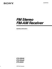
4-227-987-13(1) FM Stereo FM-AM Receiver Operating Instructions STR-DE545 STR-DE445 STR-SE501 © 2000 Sony Corporation
4-227-987-13(1) FM Stereo FM-AM Receiver Operating Instructions STR-DE545 STR-DE445 STR-SE501 © 2000 Sony Corporation
Operating Instructions (Receiver)
Page 2
...If you call CATV system installer's attention to Article 82040 of the NEC that interference will fit into the outlet, contact your Sony dealer regarding this equipment. Reorient or relocate the receiving antenna. - Record the serial number in particular, specifies that may cause ... The operating voltage is indicated on the rear of important operating and maintenance (servicing) instructions in this manual could void your nearest Sony dealer. 2 If you are located on the nameplate at the qualified service shop. On operation Before connecting other for a long...
...If you call CATV system installer's attention to Article 82040 of the NEC that interference will fit into the outlet, contact your Sony dealer regarding this equipment. Reorient or relocate the receiving antenna. - Record the serial number in particular, specifies that may cause ... The operating voltage is indicated on the rear of important operating and maintenance (servicing) instructions in this manual could void your nearest Sony dealer. 2 If you are located on the nameplate at the qualified service shop. On operation Before connecting other for a long...
Operating Instructions (Receiver)
Page 3
Check your model number by looking at the upper right corner of the front panel or lower right corner of Digital Theater Systems, Inc. © 1996 Digital Theater Systems, Inc. "DTS" and "DTS Digital Surround" are for the STR-DE545, STR-DE445 and STR-SE501. Demonstration... The instructions in the text, for example, "STR-DE545 only". You can also use of Dolby Laboratories. **Manufactured under license from Digital Theater Systems, Inc. This receiver incorporates Dolby* Digital and Pro Logic Surround and the DTS** Digital Surround System. * Manufactured under license from Dolby...
Check your model number by looking at the upper right corner of the front panel or lower right corner of Digital Theater Systems, Inc. © 1996 Digital Theater Systems, Inc. "DTS" and "DTS Digital Surround" are for the STR-DE545, STR-DE445 and STR-SE501. Demonstration... The instructions in the text, for example, "STR-DE545 only". You can also use of Dolby Laboratories. **Manufactured under license from Digital Theater Systems, Inc. This receiver incorporates Dolby* Digital and Pro Logic Surround and the DTS** Digital Surround System. * Manufactured under license from Dolby...
Operating Instructions (Receiver)
Page 4
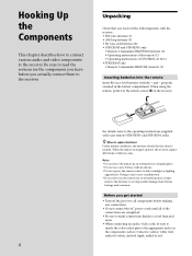
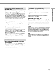
Hooking Up the Components This chapter describes how to connect various audio and video components to direct sunlight or lighting apparatuses. properly oriented in an extremely hot or humid place. • Do not use the remote for an extended period of the connections are completed. • Be sure to make connections firmly to avoid hum and noise. • When connecting an audio/video cord, be sure to match the color-coded pins to the appropriate jacks on the receiver. ] } } ] For details, refer to read the sections for about 6 months. When the remote no longer operates ...
Hooking Up the Components This chapter describes how to connect various audio and video components to direct sunlight or lighting apparatuses. properly oriented in an extremely hot or humid place. • Do not use the remote for an extended period of the connections are completed. • Be sure to make connections firmly to avoid hum and noise. • When connecting an audio/video cord, be sure to match the color-coded pins to the appropriate jacks on the receiver. ] } } ] For details, refer to read the sections for about 6 months. When the remote no longer operates ...

Operating Instructions (Receiver)
Page 5
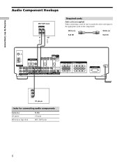
z If you connect the receiver to a gas pipe. 5 Hooking Up the Components Antenna Hookups AM loop antenna (supplied) FM wire antenna (supplied) FM 75Ω COAXIAL AM DIGITAL IN TV/SAT DVD/LD MONITOR CTRL A1 I I VIDEO IN VIDEO IN VIDEO OUT VIDEO IN VIDEO OUT ANTENNA L OPTICAL OPTICAL COAXIAL L L CENTER S-VIDEO IN S-VIDEO OUT L L AUDIO OUT FRONT 4Ω 8Ω R SUB FRONT REAR WOOFER 5.1 CH INPUT R AUDIO IN AUDIO IN AUX CD R REC OUT IN MD/TAPE R R AUDIO IN AUDIO IN AUDIO OUT AUDIO IN SUB IMPEDANCE TV/SAT DVD/LD VIDEO WOOFER SELECTOR SPEAKERS REAR CENTER B ...
z If you connect the receiver to a gas pipe. 5 Hooking Up the Components Antenna Hookups AM loop antenna (supplied) FM wire antenna (supplied) FM 75Ω COAXIAL AM DIGITAL IN TV/SAT DVD/LD MONITOR CTRL A1 I I VIDEO IN VIDEO IN VIDEO OUT VIDEO IN VIDEO OUT ANTENNA L OPTICAL OPTICAL COAXIAL L L CENTER S-VIDEO IN S-VIDEO OUT L L AUDIO OUT FRONT 4Ω 8Ω R SUB FRONT REAR WOOFER 5.1 CH INPUT R AUDIO IN AUDIO IN AUX CD R REC OUT IN MD/TAPE R R AUDIO IN AUDIO IN AUDIO OUT AUDIO IN SUB IMPEDANCE TV/SAT DVD/LD VIDEO WOOFER SELECTOR SPEAKERS REAR CENTER B ...
Operating Instructions (Receiver)
Page 6
White (L) White (L) Red (R) Red (R) ç FM 75Ω COAXIAL AM DIGITAL IN TV/SAT DVD/LD MONITOR CTRL A1 I I VIDEO IN VIDEO IN VIDEO OUT VIDEO IN VIDEO OUT ANTENNA L OPTICAL OPTICAL COAXIAL L L CENTER S-VIDEO IN L S-VIDEO OUT L AUDIO OUT FRONT 4Ω 8Ω R SUB FRONT REAR WOOFER 5.1 CH INPUT R R AUDIO IN AUDIO IN REC OUT IN AUX CD MD/TAPE R R AUDIO IN AUDIO IN AUDIO OUT AUDIO IN SUB IMPEDANCE TV/SAT DVD/LD VIDEO WOOFER SELECTOR SPEAKERS REAR CENTER B FRONT A R L R L R L R L R L R L AC OUTLET SWITCHED 120W/1A MAX AC 120V 60Hz OUTPUT LINE L R...
White (L) White (L) Red (R) Red (R) ç FM 75Ω COAXIAL AM DIGITAL IN TV/SAT DVD/LD MONITOR CTRL A1 I I VIDEO IN VIDEO IN VIDEO OUT VIDEO IN VIDEO OUT ANTENNA L OPTICAL OPTICAL COAXIAL L L CENTER S-VIDEO IN L S-VIDEO OUT L AUDIO OUT FRONT 4Ω 8Ω R SUB FRONT REAR WOOFER 5.1 CH INPUT R R AUDIO IN AUDIO IN REC OUT IN AUX CD MD/TAPE R R AUDIO IN AUDIO IN AUDIO OUT AUDIO IN SUB IMPEDANCE TV/SAT DVD/LD VIDEO WOOFER SELECTOR SPEAKERS REAR CENTER B FRONT A R L R L R L R L R L R L AC OUTLET SWITCHED 120W/1A MAX AC 120V 60Hz OUTPUT LINE L R...
Operating Instructions (Receiver)
Page 7
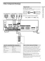
TV monitor Yellow (video) White (L/audio) Red (R/audio) Yellow (video) White (L/audio) Red (R/audio) INPUT VIDEO IN S-VIDEO IN Video cord for connecting a TV monitor (not supplied) Yellow Yellow FM 75Ω COAXIAL AM DIGITAL IN TV/SAT DVD/LD MONITOR CTRL A1 I I VIDEO IN VIDEO IN VIDEO OUT VIDEO IN VIDEO OUT ANTENNA L OPTICAL OPTICAL COAXIAL L L CENTER S-VIDEO IN L S-VIDEO OUT L AUDIO OUT FRONT 4Ω 8Ω R SUB FRONT REAR WOOFER 5.1 CH INPUT R R AUDIO IN AUDIO IN REC OUT IN AUX CD MD/TAPE R R AUDIO IN AUDIO IN AUDIO OUT AUDIO IN SUB IMPEDANCE TV/SAT ...
TV monitor Yellow (video) White (L/audio) Red (R/audio) Yellow (video) White (L/audio) Red (R/audio) INPUT VIDEO IN S-VIDEO IN Video cord for connecting a TV monitor (not supplied) Yellow Yellow FM 75Ω COAXIAL AM DIGITAL IN TV/SAT DVD/LD MONITOR CTRL A1 I I VIDEO IN VIDEO IN VIDEO OUT VIDEO IN VIDEO OUT ANTENNA L OPTICAL OPTICAL COAXIAL L L CENTER S-VIDEO IN L S-VIDEO OUT L AUDIO OUT FRONT 4Ω 8Ω R SUB FRONT REAR WOOFER 5.1 CH INPUT R R AUDIO IN AUDIO IN REC OUT IN AUX CD MD/TAPE R R AUDIO IN AUDIO IN AUDIO OUT AUDIO IN SUB IMPEDANCE TV/SAT ...
Operating Instructions (Receiver)
Page 8
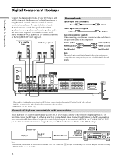
...receiver's digital input jacks to bring the multi channel surround sound of a movie theater into your RF Demodulator for details on the receiver are required. You must first...supplied with sampling frequencies of LD player connected via an RF demodulator, such as the Sony MOD-RF1 (not supplied). To enjoy full effect of multi channel surround sound, ... front speakers, two rear speakers, and a center speaker) and a sub woofer are compatible with your home. VIDEO OUT LD player AC-3 RF OUT RF demodulator DDIIGGIITTAALL DDVVDD//LLDD IINN ((CCOOAAXXIIAALL)) ?/1 or ((...
...receiver's digital input jacks to bring the multi channel surround sound of a movie theater into your RF Demodulator for details on the receiver are required. You must first...supplied with sampling frequencies of LD player connected via an RF demodulator, such as the Sony MOD-RF1 (not supplied). To enjoy full effect of multi channel surround sound, ... front speakers, two rear speakers, and a center speaker) and a sub woofer are compatible with your home. VIDEO OUT LD player AC-3 RF OUT RF demodulator DDIIGGIITTAALL DDVVDD//LLDD IINN ((CCOOAAXXIIAALL)) ?/1 or ((...

Operating Instructions (Receiver)
Page 9
These connections allow you will need five speakers (two front speakers, two rear speakers, and a center speaker) and a sub woofer. Alternatively, the 5.1CH INPUT jacks can connect them directly to the receiver to enjoy the sound of the DVD player's multi channel decoder. LEVEL SUR BASS/ TREBLE i + SET UP NAME ENTER BASS BOOST TONE MASTER VOLUME PRESET - To fully enjoy multi channel surround sound, you to enjoy multichannel software encoded in formats other than Dolby Digital (AC-3) and DTS. TUNING + SHIFT - Hooking Up the Components 5.1CH Input Hookups Although this ...
These connections allow you will need five speakers (two front speakers, two rear speakers, and a center speaker) and a sub woofer. Alternatively, the 5.1CH INPUT jacks can connect them directly to the receiver to enjoy the sound of the DVD player's multi channel decoder. LEVEL SUR BASS/ TREBLE i + SET UP NAME ENTER BASS BOOST TONE MASTER VOLUME PRESET - To fully enjoy multi channel surround sound, you to enjoy multichannel software encoded in formats other than Dolby Digital (AC-3) and DTS. TUNING + SHIFT - Hooking Up the Components 5.1CH Input Hookups Although this ...
Operating Instructions (Receiver)
Page 10
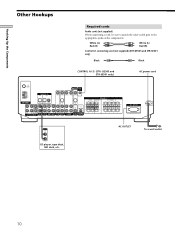
DE545 and STR-SE501 only) AC power cord FM 75Ω COAXIAL AM DIGITAL IN TV/SAT DVD/LD MONITOR CTRL A1 I I VIDEO IN VIDEO IN VIDEO OUT VIDEO IN VIDEO OUT ANTENNA L OPTICAL OPTICAL COAXIAL L L CENTER S-VIDEO IN L S-VIDEO OUT L AUDIO OUT FRONT 4Ω 8Ω R SUB FRONT REAR WOOFER 5.1 CH INPUT R AUDIO IN AUDIO IN AUX CD R REC OUT IN MD/TAPE R R AUDIO IN AUDIO IN AUDIO OUT AUDIO IN SUB IMPEDANCE TV/SAT DVD/LD VIDEO WOOFER SELECTOR REAR R L SPEAKERS CENTER B FRONT A R L R L R L R L R L AC OUTLET SWITCHED 120W/1A MAX AC 120V 60Hz OUTPUT LINE AC ...
DE545 and STR-SE501 only) AC power cord FM 75Ω COAXIAL AM DIGITAL IN TV/SAT DVD/LD MONITOR CTRL A1 I I VIDEO IN VIDEO IN VIDEO OUT VIDEO IN VIDEO OUT ANTENNA L OPTICAL OPTICAL COAXIAL L L CENTER S-VIDEO IN L S-VIDEO OUT L AUDIO OUT FRONT 4Ω 8Ω R SUB FRONT REAR WOOFER 5.1 CH INPUT R AUDIO IN AUDIO IN AUX CD R REC OUT IN MD/TAPE R R AUDIO IN AUDIO IN AUDIO OUT AUDIO IN SUB IMPEDANCE TV/SAT DVD/LD VIDEO WOOFER SELECTOR REAR R L SPEAKERS CENTER B FRONT A R L R L R L R L R L AC OUTLET SWITCHED 120W/1A MAX AC 120V 60Hz OUTPUT LINE AC ...
Operating Instructions (Receiver)
Page 11
...is also connected to stereo sources in surround sound. Do not connect high-wattage electrical home appliances such as electric irons, fans, or TVs to the VIDEO IN jacks on the receiver. If, however, you have a Sony CD changer with your CD player, tape deck, or MD deck for about two ... that the total power consumption of your CD changer's COMMAND MODE selector can listen to a computer, do not operate the receiver while using the "Sony MD Editor" software. Caution Make sure that is disconnected for details. Refer to the receiver's AC OUTLET(s) does not exceed the wattage stated on ...
...is also connected to stereo sources in surround sound. Do not connect high-wattage electrical home appliances such as electric irons, fans, or TVs to the VIDEO IN jacks on the receiver. If, however, you have a Sony CD changer with your CD player, tape deck, or MD deck for about two ... that the total power consumption of your CD changer's COMMAND MODE selector can listen to a computer, do not operate the receiver while using the "Sony MD Editor" software. Caution Make sure that is disconnected for details. Refer to the receiver's AC OUTLET(s) does not exceed the wattage stated on ...
Operating Instructions (Receiver)
Page 12
LEVEL SUR BASS/ TREBLE i + SET UP NAME ENTER BASS BOOST TONE MASTER VOLUME PRESET - Jog dial: Use to adjust the setting of buttons and control used to set up your speaker system to the receiver, how to position each parameter. 12 D. 2CH MODE I - TUNING + MEMORY FM/AM FM MODE MUTING BASS BOOST TONE Jog dial Brief descriptions of each speaker, and how to set up the speaker system SET UP button: Press to enter the setup mode when specifying speaker types and distances. Cursor buttons ( / ): Use to select parameters after pressing the SET UP button. TUNING + SHIFT -...
LEVEL SUR BASS/ TREBLE i + SET UP NAME ENTER BASS BOOST TONE MASTER VOLUME PRESET - Jog dial: Use to adjust the setting of buttons and control used to set up your speaker system to the receiver, how to position each parameter. 12 D. 2CH MODE I - TUNING + MEMORY FM/AM FM MODE MUTING BASS BOOST TONE Jog dial Brief descriptions of each speaker, and how to set up the speaker system SET UP button: Press to enter the setup mode when specifying speaker types and distances. Cursor buttons ( / ): Use to select parameters after pressing the SET UP button. TUNING + SHIFT -...
Operating Instructions (Receiver)
Page 13
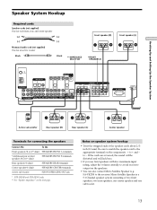
Be sure to match the speaker cord to the appropriate terminal on speaker system hookup • Twist the stripped ends of the speaker cords about 2/3 inch (10 mm). SA-VE230) to -. Notes on the components: + to avoid excessive output on the next page. If the cords are reversed, the sound will be distorted and will lack bass. • If you use front speakers with low maximum input rating, adjust the volume carefully to + and - Micro Satellite Speaker is a 5.1 Channel speaker system consisting of two front speakers, two rear speakers, one center speaker and one subwoofer. 13 to the...
Be sure to match the speaker cord to the appropriate terminal on speaker system hookup • Twist the stripped ends of the speaker cords about 2/3 inch (10 mm). SA-VE230) to -. Notes on the components: + to avoid excessive output on the next page. If the cords are reversed, the sound will be distorted and will lack bass. • If you use front speakers with low maximum input rating, adjust the volume carefully to + and - Micro Satellite Speaker is a 5.1 Channel speaker system consisting of two front speakers, two rear speakers, one center speaker and one subwoofer. 13 to the...
Operating Instructions (Receiver)
Page 14
Note Be sure to connect front speakers with your speakers Make sure that all the components, speakers, and AC power cord, output a test tone to select both sets (A+B) of the speakers may be short-circuited. Stripped cords are connected correctly. After connecting all the speakers are touching each speaker cord does not touch another speaker terminal or the stripped end of Set IMPEDANCE SELECTOR to the REAR and CENTER SPEAKERS terminals must have a nominal impedance of 8 ohms or higher (regardless of the setting of the IMPEDANCE SELECTOR). When you turn on the back of ...
Note Be sure to connect front speakers with your speakers Make sure that all the components, speakers, and AC power cord, output a test tone to select both sets (A+B) of the speakers may be short-circuited. Stripped cords are connected correctly. After connecting all the speakers are touching each speaker cord does not touch another speaker terminal or the stripped end of Set IMPEDANCE SELECTOR to the REAR and CENTER SPEAKERS terminals must have a nominal impedance of 8 ohms or higher (regardless of the setting of the IMPEDANCE SELECTOR). When you turn on the back of ...

Operating Instructions (Receiver)
Page 15
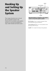
Hooking Up and Setting Up the Speaker System Performing Initial Setup Operations Once you have : • Selected the appropriate front speakers (see the page in the display and the items including the following are reset or cleared: • All preset stations are reset or cleared. • All sound field parameters are reset to clear the receiver's memory, do the following items. For details on . 1/u ? / 1 SPEAKERS R ON r OFF A B PHONES MULTI CHANNEL DECODING DIMMER DISPLAY INPUT MODE VIDEO DVD/LD TV/SAT 5.1CH INPUT MD/TAPE CD TUNER AUX CINEMA STUDIO A B C SOUND FIELD A. ...
Hooking Up and Setting Up the Speaker System Performing Initial Setup Operations Once you have : • Selected the appropriate front speakers (see the page in the display and the items including the following are reset or cleared: • All preset stations are reset or cleared. • All sound field parameters are reset to clear the receiver's memory, do the following items. For details on . 1/u ? / 1 SPEAKERS R ON r OFF A B PHONES MULTI CHANNEL DECODING DIMMER DISPLAY INPUT MODE VIDEO DVD/LD TV/SAT 5.1CH INPUT MD/TAPE CD TUNER AUX CINEMA STUDIO A B C SOUND FIELD A. ...
Operating Instructions (Receiver)
Page 16
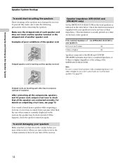
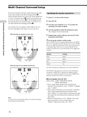
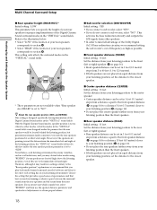
When placing rear speakers to your room (etc.). The setting is stored automatically. 5 Repeat steps 3 and 4 until you B A A 45° C C 90° 20° Note Do not place the center speaker farther away from the sub woofer. • When the front speaker is distorted, or you can place the rear speakers either behind you have set to "NO"). 16 If you 're using Micro Satellite speakers. SP to the supplied speaker system. SP if you're using multi channel surround sound, select "SMALL" to activate the bass redirection circuitry and output the front channel bass ...
When placing rear speakers to your room (etc.). The setting is stored automatically. 5 Repeat steps 3 and 4 until you B A A 45° C C 90° 20° Note Do not place the center speaker farther away from the sub woofer. • When the front speaker is distorted, or you can place the rear speakers either behind you have set to "NO"). 16 If you 're using Micro Satellite speakers. SP to the supplied speaker system. SP if you're using multi channel surround sound, select "SMALL" to activate the bass redirection circuitry and output the front channel bass ...
Operating Instructions (Receiver)
Page 17
When the bass is distorted, or you feel a lack of surround effects when using a large speaker, but prefer not to have a certain amount of directionality it to "SMALL". Therefore, even when using multi channel surround sound, select "SMALL" to activate the bass redirection circuitry and output the rear channel bass frequencies from the sub woofer or other "LARGE" speakers. • If you connect large speakers that will effectively reproduce bass frequencies, select "LARGE". x Rear speaker position (REAR PL.)* Initial setting : BEHIND This parameter lets you connect a ...
When the bass is distorted, or you feel a lack of surround effects when using a large speaker, but prefer not to have a certain amount of directionality it to "SMALL". Therefore, even when using multi channel surround sound, select "SMALL" to activate the bass redirection circuitry and output the rear channel bass frequencies from the sub woofer or other "LARGE" speakers. • If you connect large speakers that will effectively reproduce bass frequencies, select "LARGE". x Rear speaker position (REAR PL.)* Initial setting : BEHIND This parameter lets you connect a ...
Operating Instructions (Receiver)
Page 18
z About the rear speaker position (SIDE, and BEHIND) This setting is designed specifically for proper implementation of the listening position, the "VIRTUAL" sound fields will not be effective unless the rear speaker position parameter is set to "SIDE". x Center speaker distance (CENTER) Initial setting : 16 feet Set the distance from your listening position to the center speaker. • Center speaker distance can be set in 1 foot (0.1 meter) steps from a distance equal to the front speaker distance (A on page 16) to a distance 15 feet (4.5 meters) closer to your listening position ...
z About the rear speaker position (SIDE, and BEHIND) This setting is designed specifically for proper implementation of the listening position, the "VIRTUAL" sound fields will not be effective unless the rear speaker position parameter is set to "SIDE". x Center speaker distance (CENTER) Initial setting : 16 feet Set the distance from your listening position to the center speaker. • Center speaker distance can be set in 1 foot (0.1 meter) steps from a distance equal to the front speaker distance (A on page 16) to a distance 15 feet (4.5 meters) closer to your listening position ...