

Limited Warranty (US Only)
Page 1
... warranty does not cover damage due to improper operation or maintenance, connection to any part of sale, the limitation on how long an implied warranty lasts, so the above limitations or exclusions may have other than a facility authorized by Sony to service the Product. This warranty is valid only in exchange for...
... warranty does not cover damage due to improper operation or maintenance, connection to any part of sale, the limitation on how long an implied warranty lasts, so the above limitations or exclusions may have other than a facility authorized by Sony to service the Product. This warranty is valid only in exchange for...
Operating Instructions (HT-DDW650)
Page 2
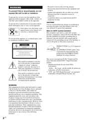
... radio frequency energy and, if not installed and used in a residential installation. This equipment generates, uses, and can be connected to the grounding system of the building, as a bookcase or built-in the literature accompanying the appliance. Don't throw away...of Digital Theater Systems, Inc. As an ENERGY STAR® partner, Sony Corporation has determined that to persons. Reorient or relocate the receiving antenna. - Connect the equipment into an outlet on , the user is connected. - CAUTION You are registered trademarks of it correctly as practical. ...
... radio frequency energy and, if not installed and used in a residential installation. This equipment generates, uses, and can be connected to the grounding system of the building, as a bookcase or built-in the literature accompanying the appliance. Don't throw away...of Digital Theater Systems, Inc. As an ENERGY STAR® partner, Sony Corporation has determined that to persons. Reorient or relocate the receiving antenna. - Connect the equipment into an outlet on , the user is connected. - CAUTION You are registered trademarks of it correctly as practical. ...
Operating Instructions (HT-DDW650)
Page 3
... 12 Hooking Up and Setting Up the Speaker System Speaker system hookups 13 Performing initial setup operations ..... 15 Multi channel surround setup 15 Checking the connections 20 Basic Operations Selecting the component 21 Changing the display 22 Enjoying Surround Sound Using only the front speakers (2 Channel Stereo 23 Enjoying higher fidelity...
... 12 Hooking Up and Setting Up the Speaker System Speaker system hookups 13 Performing initial setup operations ..... 15 Multi channel surround setup 15 Checking the connections 20 Basic Operations Selecting the component 21 Changing the display 22 Enjoying Surround Sound Using only the front speakers (2 Channel Stereo 23 Enjoying higher fidelity...
Operating Instructions (HT-DDW650)
Page 6
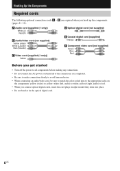
... yellow; and red (right, audio) to red. • When you get started • Turn off the power to all components before making any connections. • Do not connect the AC power cord until they click into place. • Do not bend or tie the optical digital cord. 6US E are completed. • ...Be sure to make connections firmly to avoid hum and noise. • When connecting an audio/video cord, be sure to match the color-coded pins to the appropriate jacks on the components: yellow (video...
... yellow; and red (right, audio) to red. • When you get started • Turn off the power to all components before making any connections. • Do not connect the AC power cord until they click into place. • Do not bend or tie the optical digital cord. 6US E are completed. • ...Be sure to make connections firmly to avoid hum and noise. • When connecting an audio/video cord, be sure to match the color-coded pins to the appropriate jacks on the components: yellow (video...
Operating Instructions (HT-DDW650)
Page 7
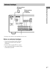
... pickup, keep the AM loop antenna away from the receiver and other components. • Be sure to fully extend the FM wire antenna. • After connecting the FM wire antenna, keep it as horizontal as possible. 7US Notes on the area code.
... pickup, keep the AM loop antenna away from the receiver and other components. • Be sure to fully extend the FM wire antenna. • After connecting the FM wire antenna, keep it as horizontal as possible. 7US Notes on the area code.
Operating Instructions (HT-DDW650)
Page 9
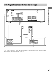
... AUDIO OUT S-VIDEO OUT Pb OPTICAL COAXIAL Note If your TV has COMPONENT VIDEO input jacks, you can use a component video cord (not supplied) to connect the DVD Player/Video Cassette Recorder to your TV. 9US
... AUDIO OUT S-VIDEO OUT Pb OPTICAL COAXIAL Note If your TV has COMPONENT VIDEO input jacks, you can use a component video cord (not supplied) to connect the DVD Player/Video Cassette Recorder to your TV. 9US
Operating Instructions (HT-DDW650)
Page 10
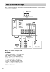
...VIDEO 2 AUDIO IN jacks on the receiver. Video component hookups If you are not going to hookup a DVD Player/Video Cassette Recorder, you are connecting a separate satellite tuner, connect both the audio and video output jacks to the receiver as shown below. C INPUT VIDEO IN TV monitor 10US If you can... connect your video components as shown above. In this case, do not connect the TV's video output jack to the VIDEO 2 VIDEO IN jack on the receiver and apply sound effects ...
...VIDEO 2 AUDIO IN jacks on the receiver. Video component hookups If you are not going to hookup a DVD Player/Video Cassette Recorder, you are connecting a separate satellite tuner, connect both the audio and video output jacks to the receiver as shown below. C INPUT VIDEO IN TV monitor 10US If you can... connect your video components as shown above. In this case, do not connect the TV's video output jack to the VIDEO 2 VIDEO IN jack on the receiver and apply sound effects ...
Operating Instructions (HT-DDW650)
Page 11
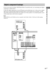
Connect the digital output jacks of your DVD player and satellite tuner (etc.) to the receiver's digital input jacks to hookup a DVD Player/Video Cassette Recorder, ...
Connect the digital output jacks of your DVD player and satellite tuner (etc.) to the receiver's digital input jacks to hookup a DVD Player/Video Cassette Recorder, ...
Operating Instructions (HT-DDW650)
Page 12
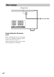
Other hookups AC power cord RL RL RL RL FRONT CENTER SURROUND SPEAKERS IMPEDANCE USE 8 - 16Ω Connecting the AC power cord Before connecting the AC power cord of your audio/ video components to the receiver (page 13). b To a wall outlet 12US Connect the AC power cord(s) of this receiver to a wall outlet, connect the speaker system to a wall outlet.
Other hookups AC power cord RL RL RL RL FRONT CENTER SURROUND SPEAKERS IMPEDANCE USE 8 - 16Ω Connecting the AC power cord Before connecting the AC power cord of your audio/ video components to the receiver (page 13). b To a wall outlet 12US Connect the AC power cord(s) of this receiver to a wall outlet, connect the speaker system to a wall outlet.
Operating Instructions (HT-DDW650)
Page 13
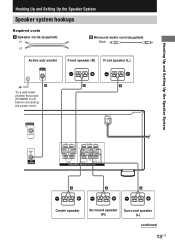
... audio cord (supplied) Black Active sub woofer INPUT AUDIO IN Front speaker (R) Front speaker (L) e Ee E b B To a wall outlet (Switch the power (POWER) to off before connecting the power cord.) A A MONITOR VIDEO OUT AUDIO OUT SUB WOOFER RL RL RL RL FRONT CENTER SURROUND SPEAKERS IMPEDANCE USE 8 - 16Ω E A A A e Ee Ee Center...
... audio cord (supplied) Black Active sub woofer INPUT AUDIO IN Front speaker (R) Front speaker (L) e Ee E b B To a wall outlet (Switch the power (POWER) to off before connecting the power cord.) A A MONITOR VIDEO OUT AUDIO OUT SUB WOOFER RL RL RL RL FRONT CENTER SURROUND SPEAKERS IMPEDANCE USE 8 - 16Ω E A A A e Ee Ee Center...
Operating Instructions (HT-DDW650)
Page 14
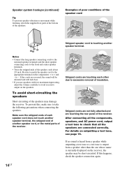
...damage the receiver. To avoid short-circuiting the speakers Short-circuiting of the receiver. Stripped cords are not fully attached and are connected correctly. After connecting all the components, speakers, and AC power cord, output a test tone to check that all the speakers are touching the rear... speaker cord does not touch another speaker terminal, the stripped end of another speaker terminal. To prevent this happens, check the speaker connection again. 14US Make sure the stripped ends of insulation. Stripped cords are reversed, the sound will be short-circuited. If no sound...
...damage the receiver. To avoid short-circuiting the speakers Short-circuiting of the receiver. Stripped cords are not fully attached and are connected correctly. After connecting all the components, speakers, and AC power cord, output a test tone to check that all the speakers are touching the rear... speaker cord does not touch another speaker terminal, the stripped end of another speaker terminal. To prevent this happens, check the speaker connection again. 14US Make sure the stripped ends of insulation. Stripped cords are reversed, the sound will be short-circuited. If no sound...
Operating Instructions (HT-DDW650)
Page 15
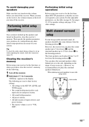
... MIN". Tip To check the audio output during settings (to set to 5 feet closer (B) and the surround speakers up while outputting the sound), check the connection (page 20). Clearing the receiver's memory Before using your receiver for your receiver for 5 seconds. See pages 15-19 for speaker settings and page 33...
... MIN". Tip To check the audio output during settings (to set to 5 feet closer (B) and the surround speakers up while outputting the sound), check the connection (page 20). Clearing the receiver's memory Before using your receiver for your receiver for 5 seconds. See pages 15-19 for speaker settings and page 33...
Operating Instructions (HT-DDW650)
Page 18
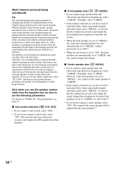
... distance parameter and speaker level adjustments to the effect each listening environment has many variables, like wall reflections. Only when you do not connect a sub woofer, select "NO". SP." (Normal Speaker), see page 16. With the Digital Cinema Sound modes, speaker placement is ...Digital Cinema Sound modes with virtual elements will not be as other modes. x Front speaker size ( L R XXXXX) • If you connect large speakers that you feel a lack of the front speakers. Normally, select "LARGE". The sound of the center channel will effectively reproduce bass ...
... distance parameter and speaker level adjustments to the effect each listening environment has many variables, like wall reflections. Only when you do not connect a sub woofer, select "NO". SP." (Normal Speaker), see page 16. With the Digital Cinema Sound modes, speaker placement is ...Digital Cinema Sound modes with virtual elements will not be as other modes. x Front speaker size ( L R XXXXX) • If you connect large speakers that you feel a lack of the front speakers. Normally, select "LARGE". The sound of the center channel will effectively reproduce bass ...
Operating Instructions (HT-DDW650)
Page 19
Hooking Up and Setting Up the Speaker System x Surround speaker size ( SL SR XXXXX) • If you connect large speakers that will hear the test tone from each speaker in sequence. If the overall sound level is not enough bass, you can use .... To adjust the bass, see page 27. While adjusting, the test tone is output from that speaker, set them to "LARGE" if you do not connect surround speakers, select "NO".*3 Tip *1-*3 correspond to cut from that channel.
Hooking Up and Setting Up the Speaker System x Surround speaker size ( SL SR XXXXX) • If you connect large speakers that will hear the test tone from each speaker in sequence. If the overall sound level is not enough bass, you can use .... To adjust the bass, see page 27. While adjusting, the test tone is output from that speaker, set them to "LARGE" if you do not connect surround speakers, select "NO".*3 Tip *1-*3 correspond to cut from that channel.
Operating Instructions (HT-DDW650)
Page 20
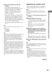
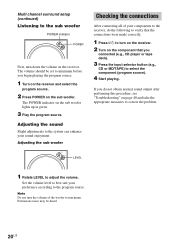
... to the sub woofer POWER indicator POWER First, turn the volume of your components to the receiver, do the following to verify that the connections were made correctly. 1 Press ?/1 to turn on the receiver. 2 Turn on the component that you do not obtain normal sound output after... page 40 and take the appropriate measures to correct the problem. Adjusting the sub woofer Checking the connections After connecting all of the woofer to select the component (program source). 4 Start playing. If you connected (e.g., CD player or tape deck). 3 Press the input selector button (e.g., CD or MD/TAPE)...
... to the sub woofer POWER indicator POWER First, turn the volume of your components to the receiver, do the following to verify that the connections were made correctly. 1 Press ?/1 to turn on the receiver. 2 Turn on the component that you do not obtain normal sound output after... page 40 and take the appropriate measures to correct the problem. Adjusting the sub woofer Checking the connections After connecting all of the woofer to select the component (program source). 4 Start playing. If you connected (e.g., CD player or tape deck). 3 Press the input selector button (e.g., CD or MD/TAPE)...
Operating Instructions (HT-DDW650)
Page 21
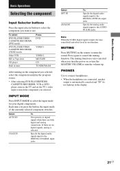
...the analog audio signals input to cancel the muting function. Press again to the AUDIO IN (L/R) jacks. PHONES Use to connect headphones. • When the headphones are connected, speaker output is selected. Each time you want to use. MUTING Press MUTING on or turn the MASTER VOLUME to ...component switches. Select OPT IN ANALOG To Specify the digital audio signals input to mute the sound. If there are both digital and analog connections. To select DVD PLAYER/VIDEO CASSETTE RECORDER (DVD mode) DVD PLAYER/VIDEO CASSETTE RECORDER (VIDEO mode) Other VCR MD or Tape deck ...
...the analog audio signals input to cancel the muting function. Press again to the AUDIO IN (L/R) jacks. PHONES Use to connect headphones. • When the headphones are connected, speaker output is selected. Each time you want to use. MUTING Press MUTING on or turn the MASTER VOLUME to ...component switches. Select OPT IN ANALOG To Specify the digital audio signals input to mute the sound. If there are both digital and analog connections. To select DVD PLAYER/VIDEO CASSETTE RECORDER (DVD mode) DVD PLAYER/VIDEO CASSETTE RECORDER (VIDEO mode) Other VCR MD or Tape deck ...
Operating Instructions (HT-DDW650)
Page 26
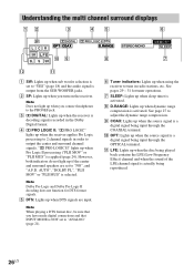
... to tune in order to output the center and surround channel signals. Note When playing a DTS format disc, be sure that you have made digital connections and that INPUT MODE is a digital signal being input through the OPTICAL terminal. PRO LOGIC II" lights up when Pro Logic II processing ("PLII MOV... up when sleep timer is activated. 8 D.RANGE: Lights up when dynamic range compression is output from the SUB WOOFER jacks. 2 SP: Lights up when you connect headphones to the PHONES jack. 3 ;
... to tune in order to output the center and surround channel signals. Note When playing a DTS format disc, be sure that you have made digital connections and that INPUT MODE is a digital signal being input through the OPTICAL terminal. PRO LOGIC II" lights up when Pro Logic II processing ("PLII MOV... up when sleep timer is activated. 8 D.RANGE: Lights up when dynamic range compression is output from the SUB WOOFER jacks. 2 SP: Lights up when you connect headphones to the PHONES jack. 3 ;
Operating Instructions (HT-DDW650)
Page 29
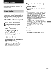
... the remote repeatedly to stereo mode, press FM MODE again. Example 1: FM 102.50 MHz 1 b0 b2 b5b 0 Example 2: AM 1350 kHz (You don't have connected FM and AM antennas to enjoy the stereo effect, but the sound will not be changed (page 44). 29US If the entered numbers still flash...
... the remote repeatedly to stereo mode, press FM MODE again. Example 1: FM 102.50 MHz 1 b0 b2 b5b 0 Example 2: AM 1350 kHz (You don't have connected FM and AM antennas to enjoy the stereo effect, but the sound will not be changed (page 44). 29US If the entered numbers still flash...
Operating Instructions (HT-DDW650)
Page 32
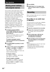
... for another station or program source. to select a character, then press MENU to move the cursor to 8 characters for . If you 've connected all components properly. For example, two VCRs can be entered for playing. To name a program source Select the program source (component) to be named...can be specified as "VHS" and "8MM", respectively. It is also handy for identifying components connected to jacks meant for another type of component, for example, a second CD player connected to assign index name for distinguishing components of the same kind. Recording on an audio tape or...
... for another station or program source. to select a character, then press MENU to move the cursor to 8 characters for . If you 've connected all components properly. For example, two VCRs can be entered for playing. To name a program source Select the program source (component) to be named...can be specified as "VHS" and "8MM", respectively. It is also handy for identifying components connected to jacks meant for another type of component, for example, a second CD player connected to assign index name for distinguishing components of the same kind. Recording on an audio tape or...
Operating Instructions (HT-DDW650)
Page 33
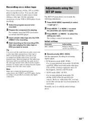
...can record from a VCR, a TV or a DVD player using the SET UP menu The SET UP menu allows you to make both digital and analog connections to adjust. 3 Press MENU + or MENU - The setting is with audio CDs, you need help. 1 Select the program source to start recording from... another audio source, select the program source, then start playing the video tape or DVD you make only digital connections. XXXX) Sets the appropriate decoding for VIDEO 2) x Decode priority (DEC. For example, insert the DVD you want to record into the DVD player. 3 ...
...can record from a VCR, a TV or a DVD player using the SET UP menu The SET UP menu allows you to make both digital and analog connections to adjust. 3 Press MENU + or MENU - The setting is with audio CDs, you need help. 1 Select the program source to start recording from... another audio source, select the program source, then start playing the video tape or DVD you make only digital connections. XXXX) Sets the appropriate decoding for VIDEO 2) x Decode priority (DEC. For example, insert the DVD you want to record into the DVD player. 3 ...


