

Service Manual
Page 1
...critiques pour la sécurité. Replace only with this Manual. HDR-SR5/SR5C/SR5E/SR7/SR7E/SR8/SR8E RMT-835 SERVICE MANUAL Ver. 1.3 2007.11 Revision History About this service manual Revised-1 Replace the previously issued SERVICE MANUAL 9-852-202-31 with part number specified. Ne les remplacer...Board • Precaution on Replacing the CABINET (G) ASSY The components identified by Kohda TEC DIGITAL VIDEO CAMERA RECORDER HDR-SR5/SR5C/SR5E/SR7/SR7E/SR8/SR8E_L2 9-852-202-32 Sony EMCS Co. 2007K0800-1 © 2007.11 Published by mark 0 or dotted line with mark 0 are critical...
...critiques pour la sécurité. Replace only with this Manual. HDR-SR5/SR5C/SR5E/SR7/SR7E/SR8/SR8E RMT-835 SERVICE MANUAL Ver. 1.3 2007.11 Revision History About this service manual Revised-1 Replace the previously issued SERVICE MANUAL 9-852-202-31 with part number specified. Ne les remplacer...Board • Precaution on Replacing the CABINET (G) ASSY The components identified by Kohda TEC DIGITAL VIDEO CAMERA RECORDER HDR-SR5/SR5C/SR5E/SR7/SR7E/SR8/SR8E_L2 9-852-202-32 Sony EMCS Co. 2007K0800-1 © 2007.11 Published by mark 0 or dotted line with mark 0 are critical...

Service Manual
Page 2
...projecting parts, and the NPFH60 rechargeable battery pack attached HDR-SR5/SR5C/SR5E/SR7/SR7E/SR8/SR8E_L2 - 2 - Input/Output ...format can have additional information such as your camcorder's setting information at load impedance 47 kΩ...manual of HDR-SR5E/SR7E/SR8E. CD-ROM "Handycam Application Software" (1) - ENGLISH JAPANESE System Video compression format AVCHD (HD)/MPEG2 (SD)/JPEG (Still images) Audio compression format Dolby Digital 2/5.1ch Dolby Digital 5.1 Creator Video signal PAL color, CCIR standards 1080/50i specification Hard disk HDR-SR5E: 40 GB HDR-SR7E: 60 GB HDR...
...projecting parts, and the NPFH60 rechargeable battery pack attached HDR-SR5/SR5C/SR5E/SR7/SR7E/SR8/SR8E_L2 - 2 - Input/Output ...format can have additional information such as your camcorder's setting information at load impedance 47 kΩ...manual of HDR-SR5E/SR7E/SR8E. CD-ROM "Handycam Application Software" (1) - ENGLISH JAPANESE System Video compression format AVCHD (HD)/MPEG2 (SD)/JPEG (Still images) Audio compression format Dolby Digital 2/5.1ch Dolby Digital 5.1 Creator Video signal PAL color, CCIR standards 1080/50i specification Hard disk HDR-SR5E: 40 GB HDR-SR7E: 60 GB HDR...

Service Manual
Page 3
...manual... [OUTDOOR] (5 800 K) HDR-SR5/SR5C/SR5E/SR7/SR7E/SR8/SR8E_L2 Minimum ...camcorder's setting information at the time of recording. *2 The unique pixel array of Sony...'s ClearVid CMOS sensor and image processing system (new Enhanced Imaging Processor) allows for other specifications. Picture Motion Browser (Software) - ENGLISH JAPANESE SPECIFICATIONS System Video compression format AVCHD (HD)/MPEG2 (SD)/JPEG (Still images) Audio compression format Dolby Digital 2/5.1ch Dolby Digital 5.1 Creator Video signal NTSC color, EIA standards 1080/60i specification Hard disk HDR-SR5...
...manual... [OUTDOOR] (5 800 K) HDR-SR5/SR5C/SR5E/SR7/SR7E/SR8/SR8E_L2 Minimum ...camcorder's setting information at the time of recording. *2 The unique pixel array of Sony...'s ClearVid CMOS sensor and image processing system (new Enhanced Imaging Processor) allows for other specifications. Picture Motion Browser (Software) - ENGLISH JAPANESE SPECIFICATIONS System Video compression format AVCHD (HD)/MPEG2 (SD)/JPEG (Still images) Audio compression format Dolby Digital 2/5.1ch Dolby Digital 5.1 Creator Video signal NTSC color, EIA standards 1080/60i specification Hard disk HDR-SR5...
Service Manual
Page 6
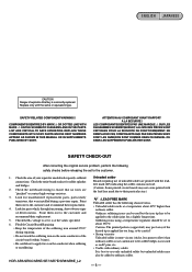
...CAUTION Danger of unleaded solder are printed with the leadfree mark (LF) indicating the solder contains no wires are "pinched" or contact high-wattage resistors. 3. LES COMPOSANTS IDENTIFÉS PAR UNE MARQUE 0 SUR LES DIAGRAMMES SCHÉMATIQUES ET LA LISTE DES PI&#... same conductor of deterioration. REPLACE THESE COMPONENTS WITH SONY PARTS WHOSE PART NUMBERS APPEAR AS SHOWN IN THIS MANUAL OR IN SUPPLEMENTS PUBLISHED BY SONY. Check the entire board surface for unsoldered or poorly-soldered connections. HDR-SR5/SR5C/SR5E/SR7/SR7E/SR8/SR8E_L2 Unleaded solder Boards requiring use...
...CAUTION Danger of unleaded solder are printed with the leadfree mark (LF) indicating the solder contains no wires are "pinched" or contact high-wattage resistors. 3. LES COMPOSANTS IDENTIFÉS PAR UNE MARQUE 0 SUR LES DIAGRAMMES SCHÉMATIQUES ET LA LISTE DES PI&#... same conductor of deterioration. REPLACE THESE COMPONENTS WITH SONY PARTS WHOSE PART NUMBERS APPEAR AS SHOWN IN THIS MANUAL OR IN SUPPLEMENTS PUBLISHED BY SONY. Check the entire board surface for unsoldered or poorly-soldered connections. HDR-SR5/SR5C/SR5E/SR7/SR7E/SR8/SR8E_L2 Unleaded solder Boards requiring use...
Service Manual
Page 8
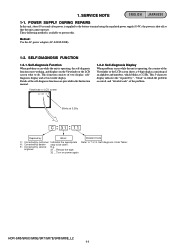
... is operating, the counter of the Viewfinder or the LCD screen shows a 4-digit display consisting of the self-diagnosis functions are provided in the Instruction manual. Self-diagnosis Code Table". This function consists of the problem. Self-diagnosis Display When problems occur while the unit is shut off so that the... FUNCTION 1-2-1. Details of an alphabet and numbers, which the problem occurred, and "detailed code" of two display; SERVICE NOTE ENGLISH JAPANESE 1-1. Viewfinder or LCD screen C : 3 1 : 1 1 1-2-2. 1. HDR-SR5/SR5C/SR5E/SR7/SR7E/SR8/SR8E_L2 1-1
... is operating, the counter of the Viewfinder or the LCD screen shows a 4-digit display consisting of the self-diagnosis functions are provided in the Instruction manual. Self-diagnosis Code Table". This function consists of the problem. Self-diagnosis Display When problems occur while the unit is shut off so that the... FUNCTION 1-2-1. Details of an alphabet and numbers, which the problem occurred, and "detailed code" of two display; SERVICE NOTE ENGLISH JAPANESE 1-1. Viewfinder or LCD screen C : 3 1 : 1 1 1-2-2. 1. HDR-SR5/SR5C/SR5E/SR7/SR7E/SR8/SR8E_L2 1-1

Service Manual
Page 9
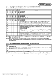
... 0 Drive fault Inspect or replacement of CN5301 on the LD-228 board: SR5/SR5C/SR5E, pin qh, qk of the hard disk drive. Handshake...Overheating (Yaw)) Occurred] (SR7/SR7E/SR8/SR8E only). HDR-SR5/SR5C/SR5E/SR7/SR7E/SR8/SR8E_L2 1-2 Self-diagnosis Code Table Self-...SR5E, pin w;, wa of flash unit. After the adjustment, be sure to [1-3-4. Use the InfoLITHIUM battery. Inspect the EEPROM (IC1804 on the LD-228 board) when zooming is unformatted. Refer to perform "GYRO Sensor Sensitivity Adjustment". If it again and operate your camcorder again C3 2 6 0 Difficult to Service Manual...
... 0 Drive fault Inspect or replacement of CN5301 on the LD-228 board: SR5/SR5C/SR5E, pin qh, qk of the hard disk drive. Handshake...Overheating (Yaw)) Occurred] (SR7/SR7E/SR8/SR8E only). HDR-SR5/SR5C/SR5E/SR7/SR7E/SR8/SR8E_L2 1-2 Self-diagnosis Code Table Self-...SR5E, pin w;, wa of flash unit. After the adjustment, be sure to [1-3-4. Use the InfoLITHIUM battery. Inspect the EEPROM (IC1804 on the LD-228 board) when zooming is unformatted. Refer to perform "GYRO Sensor Sensitivity Adjustment". If it again and operate your camcorder again C3 2 6 0 Difficult to Service Manual...
Service Manual
Page 10
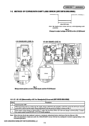
...VC-504 board) periphery. After the adjustment, make sure with an oscilloscope the output voltage of R5792 in Fig. 2, replace the lens block (Note). HDR-SR5/SR5C/SR5E/SR7/SR7E/SR8/SR8E_L2 1-3 ENGLISH JAPANESE 1-3. E : 62 : 02 [Abnormality of IC for Steadyshot] Occurred (SR7/SR7E/SR8/SR8E) Order Procedure 1...steadyshot functions appropriately in output voltage of low section will vary a little depending on the LD-228 board, turn the power ON to Service Manual, ADJ. If it does not change as shown in Fig. 2, inspect the camera control circuit (IC1803 of IC5703 on the conditions. Fig...
...VC-504 board) periphery. After the adjustment, make sure with an oscilloscope the output voltage of R5792 in Fig. 2, replace the lens block (Note). HDR-SR5/SR5C/SR5E/SR7/SR7E/SR8/SR8E_L2 1-3 ENGLISH JAPANESE 1-3. E : 62 : 02 [Abnormality of IC for Steadyshot] Occurred (SR7/SR7E/SR8/SR8E) Order Procedure 1...steadyshot functions appropriately in output voltage of low section will vary a little depending on the LD-228 board, turn the power ON to Service Manual, ADJ. If it does not change as shown in Fig. 2, inspect the camera control circuit (IC1803 of IC5703 on the conditions. Fig...
Service Manual
Page 11
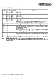
... 80 7D48 00 Write the data. 8 11 80 6BB2 00 Write the data. 9 Check if the shift lens moves while setting the order 2 to Service Manual, ADJ. When the shift lens moved, proceed to the order 10. 10 While setting the order 2 to 7, measure with an oscilloscope the output voltage of... R5721 in the periphery of VC-504 board) pe riphery. HDR-SR5/SR5C/SR5E/SR7/SR7E/SR8/SR8E_L2 1-4 If it is likely to the order 12. 12 Turn the power OFF. After the adjustment, make sure with an oscilloscope...
... 80 7D48 00 Write the data. 8 11 80 6BB2 00 Write the data. 9 Check if the shift lens moves while setting the order 2 to Service Manual, ADJ. When the shift lens moved, proceed to the order 10. 10 While setting the order 2 to 7, measure with an oscilloscope the output voltage of... R5721 in the periphery of VC-504 board) pe riphery. HDR-SR5/SR5C/SR5E/SR7/SR7E/SR8/SR8E_L2 1-4 If it is likely to the order 12. 12 Turn the power OFF. After the adjustment, make sure with an oscilloscope...
Service Manual
Page 12
...adjustment. Note 1: Finish this operation within 10 seconds. Note 2: When the lens block was replaced, execute the necessary adjustment items referring to Service Manual, ADJ. HDR-SR5/SR5C/SR5E/SR7/SR7E/SR8/SR8E_L2 1-5 E : 62 : 20 [Abnormality of Thermistor] Occurred (SR7/SR7E/SR8/SR8E) Order Procedure 1 Turn the power ...not move, replace the lens block (Note 2). Note: When the lens block was replaced, execute the necessary adjustment items referring to Service Manual, ADJ. When the shift lens moved, proceed to the order 10. 10 While setting the order 2 to 7, measure with the ...
...adjustment. Note 1: Finish this operation within 10 seconds. Note 2: When the lens block was replaced, execute the necessary adjustment items referring to Service Manual, ADJ. HDR-SR5/SR5C/SR5E/SR7/SR7E/SR8/SR8E_L2 1-5 E : 62 : 20 [Abnormality of Thermistor] Occurred (SR7/SR7E/SR8/SR8E) Order Procedure 1 Turn the power ...not move, replace the lens block (Note 2). Note: When the lens block was replaced, execute the necessary adjustment items referring to Service Manual, ADJ. When the shift lens moved, proceed to the order 10. 10 While setting the order 2 to 7, measure with the ...
Service Manual
Page 13
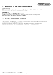
...written in it must be deactivated. USB SERIAL No. Flash error code can be initialized by high voltage, setting of repairing board also might be changed automatically to original setting. HDR-SR5/SR5C/SR5E/SR7/SR7E/SR8/SR8E_L2 1-6 INPUT". 1-5. The set is changed to disabling charge and flash...unique ID (USB Serial No.) written in a new board for service, and therefore it . Refer to Service Manual ADJ, and perform "USB SERIAL No. Refer to Service Manual ADJ, and perform "DESTINATION DATA WRITE". Note: For "Clear All record-data", refer to prevent any abnormal ...
...written in it must be deactivated. USB SERIAL No. Flash error code can be initialized by high voltage, setting of repairing board also might be changed automatically to original setting. HDR-SR5/SR5C/SR5E/SR7/SR7E/SR8/SR8E_L2 1-6 INPUT". 1-5. The set is changed to disabling charge and flash...unique ID (USB Serial No.) written in a new board for service, and therefore it . Refer to Service Manual ADJ, and perform "USB SERIAL No. Refer to Service Manual ADJ, and perform "DESTINATION DATA WRITE". Note: For "Clear All record-data", refer to prevent any abnormal ...
Service Manual
Page 49
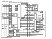
...L7 NF_DRIVE+ L6 1 7 IC5401 FOCUS DRIVE (2/4) 2 FOCUS+_OUT F3 CN5305 SHUTTER_XA 1 SHUTTER_XB 4 SHUTTER_A 3 SHUTTER_B 2 LENS_COVER_OPEN 8 LENS_COVER_LED_ON 9 LENS BARRIER FP-717 FLEXIBLE BOARD (SR7/SR7E/SR8/SR8E) CN5306 DIAL_B DIAL_B 1 DIAL_A 3 DIAL_A S7171 MANUAL PON SW PON SW 5 SR7/SR7E/...(3/3) CAMERA SIGNAL PROCESS (4/21) 3 OVERALL (2/7) (PAGE 3-2) 1 OVERALL (1/7) (PAGE 3-1) 46, 47 44, 45 42, 43 40, 41 08 HDR-SR5/SR5C/SR5E/SR7/SR7E/SR8/SR8E_L2 3-6 Ver. 1.1 2007.06 3-6. YAW- J1 I_DRIVE+ H1 I_HALL+ C5 I_BIAS- L2 ND_BIAS- Q5301 IC5404 SHUTTER_XA F2 IC5801 C5...
...L7 NF_DRIVE+ L6 1 7 IC5401 FOCUS DRIVE (2/4) 2 FOCUS+_OUT F3 CN5305 SHUTTER_XA 1 SHUTTER_XB 4 SHUTTER_A 3 SHUTTER_B 2 LENS_COVER_OPEN 8 LENS_COVER_LED_ON 9 LENS BARRIER FP-717 FLEXIBLE BOARD (SR7/SR7E/SR8/SR8E) CN5306 DIAL_B DIAL_B 1 DIAL_A 3 DIAL_A S7171 MANUAL PON SW PON SW 5 SR7/SR7E/...(3/3) CAMERA SIGNAL PROCESS (4/21) 3 OVERALL (2/7) (PAGE 3-2) 1 OVERALL (1/7) (PAGE 3-1) 46, 47 44, 45 42, 43 40, 41 08 HDR-SR5/SR5C/SR5E/SR7/SR7E/SR8/SR8E_L2 3-6 Ver. 1.1 2007.06 3-6. YAW- J1 I_DRIVE+ H1 I_HALL+ C5 I_BIAS- L2 ND_BIAS- Q5301 IC5404 SHUTTER_XA F2 IC5801 C5...

Service Manual
Page 56
... SCHEMATIC DIAGRAMS Link CK-183 BOARD (CONTROL SWITCH) PD-324 BOARD (LCD DRIVE) JK-342 BOARD (JACK) ST-175 BOARD (FLASH DRIVE) MS-374 BOARD (MS CONNECTOR) BL-013 BOARD : SR7/SR7E/SR8/SR8E... (EVF, EVF BACKLIGHT) FP-515 FLEXIBLE BOARD (HDD CONNECTION) FP-537 FLEXIBLE BOARD (CK-PD CONNECTION) FP-546 FLEXIBLE BOARD (PANEL REVERSE DETECTION SWITCH) FP-712 FLEXIBLE BOARD (LENS BARRIER) FP-717 FLEXIBLE BOARD : SR7/SR7E/SR8/SR8E (MANUAL...) COMMON NOTE FOR SCHEMATIC DIAGRAMS SIGNAL LOCATION HDR-SR5/SR5C/SR5E/SR7/SR7E/SR8/SR8E_L2
... SCHEMATIC DIAGRAMS Link CK-183 BOARD (CONTROL SWITCH) PD-324 BOARD (LCD DRIVE) JK-342 BOARD (JACK) ST-175 BOARD (FLASH DRIVE) MS-374 BOARD (MS CONNECTOR) BL-013 BOARD : SR7/SR7E/SR8/SR8E... (EVF, EVF BACKLIGHT) FP-515 FLEXIBLE BOARD (HDD CONNECTION) FP-537 FLEXIBLE BOARD (CK-PD CONNECTION) FP-546 FLEXIBLE BOARD (PANEL REVERSE DETECTION SWITCH) FP-712 FLEXIBLE BOARD (LENS BARRIER) FP-717 FLEXIBLE BOARD : SR7/SR7E/SR8/SR8E (MANUAL...) COMMON NOTE FOR SCHEMATIC DIAGRAMS SIGNAL LOCATION HDR-SR5/SR5C/SR5E/SR7/SR7E/SR8/SR8E_L2

Service Manual
Page 68
...LND002 2 SHUTTER_XA LND001 1 1 2 A CONTROL SWITCH BLOCK (AD11800) 1Pin-6Pin PAGE 4-48 of LEVEL 2 DIAL_B 6P CN7171 1 DIAL_B 2 REG_GND 3 REG_GND 4 DIAL_A 5 B DIAL_A 6 S7171 MANUAL 2 1 4 3 C D D 3 4 A Pin DIAL_B LND001 1 REG_GND LND002 2 LD-228 B DIAL_A REG_GND PON SW LND003 LND004 LND005 3 (1/4) CN5306 4 PAGE 4-28 5 of ... D E E E F FP-712 FLEXIBLE BOARD F F LENS BARRIER (PRINTED WIRING BOARD is omitted.) 08 08 HDR-SR5/SR5C/SR5E/SR7/SR7E/SR8/SR8E_L2 4-40 E FP-717 FLEXIBLE BOARD F MANUAL CONTROL SWITCH :SR7/SR7E/SR8/SR8E FP-712, FP-717
...LND002 2 SHUTTER_XA LND001 1 1 2 A CONTROL SWITCH BLOCK (AD11800) 1Pin-6Pin PAGE 4-48 of LEVEL 2 DIAL_B 6P CN7171 1 DIAL_B 2 REG_GND 3 REG_GND 4 DIAL_A 5 B DIAL_A 6 S7171 MANUAL 2 1 4 3 C D D 3 4 A Pin DIAL_B LND001 1 REG_GND LND002 2 LD-228 B DIAL_A REG_GND PON SW LND003 LND004 LND005 3 (1/4) CN5306 4 PAGE 4-28 5 of ... D E E E F FP-712 FLEXIBLE BOARD F F LENS BARRIER (PRINTED WIRING BOARD is omitted.) 08 08 HDR-SR5/SR5C/SR5E/SR7/SR7E/SR8/SR8E_L2 4-40 E FP-717 FLEXIBLE BOARD F MANUAL CONTROL SWITCH :SR7/SR7E/SR8/SR8E FP-712, FP-717

Service Manual
Page 88
FP-729 FLEXIBLE BOARD D7292 (TALLY) 1 4 IC7291 2 D7291 (NIGHT SHOT) 3 C7291 08 LND008 LND007 LND006 LND005 LND004 LND003 LND002 LND001 1-873-205- 11 HDR-SR5/SR5C/SR5E/SR7/SR7E/SR8/SR8E_L2 4-72E FP-717, FP-718, FP-719, FP-729 Ver. 1.1 2007.06 FP-717 (1 layer), FP-718 (2 layers), FP-719 (2... layers), FP-729 (1 layer), : Uses unleaded solder. FP-717 FLEXIBLE BOARD : SR7/SR7E/SR8/SR8E 1 CN7171 6 MANUAL 1 2 S7171 3 4 08 FP-718 FLEXIBLE BOARD LND052 ...
FP-729 FLEXIBLE BOARD D7292 (TALLY) 1 4 IC7291 2 D7291 (NIGHT SHOT) 3 C7291 08 LND008 LND007 LND006 LND005 LND004 LND003 LND002 LND001 1-873-205- 11 HDR-SR5/SR5C/SR5E/SR7/SR7E/SR8/SR8E_L2 4-72E FP-717, FP-718, FP-719, FP-729 Ver. 1.1 2007.06 FP-717 (1 layer), FP-718 (2 layers), FP-719 (2... layers), FP-729 (1 layer), : Uses unleaded solder. FP-717 FLEXIBLE BOARD : SR7/SR7E/SR8/SR8E 1 CN7171 6 MANUAL 1 2 S7171 3 4 08 FP-718 FLEXIBLE BOARD LND052 ...

Service Manual
Page 104
HDR-SR5/SR5C/SR5E/SR7/SR7E/SR8/SR8E_L2 5-17 FP-515 FP-546 FP-717 FP-718 FP-719 FP-720 FP-721 FP-722 FP-729 JK-342 ...-837-91 CERAMIC CHIP 1uF < DIODE > 10% 6.3V < CONNECTOR > * CN7171 1-816-654-51 FFC/FPC CONNECTOR (LIF) 6P < SWITCH > S7171 1-786-157-31 TACTILE SWITCH (MANUAL A-1274-040-A FP-718 FLEXIBLE BOARD, COMPLETE (CN7181 is not supplied, but this is included in the FP-718 flexible complete board.) < CONNECTOR > D7291 6-500...
HDR-SR5/SR5C/SR5E/SR7/SR7E/SR8/SR8E_L2 5-17 FP-515 FP-546 FP-717 FP-718 FP-719 FP-720 FP-721 FP-722 FP-729 JK-342 ...-837-91 CERAMIC CHIP 1uF < DIODE > 10% 6.3V < CONNECTOR > * CN7171 1-816-654-51 FFC/FPC CONNECTOR (LIF) 6P < SWITCH > S7171 1-786-157-31 TACTILE SWITCH (MANUAL A-1274-040-A FP-718 FLEXIBLE BOARD, COMPLETE (CN7181 is not supplied, but this is included in the FP-718 flexible complete board.) < CONNECTOR > D7291 6-500...

Service Manual
Page 108
...US, E:NTSC, JE) 3-210-378-41 (PORTUGUESE) (E: NTSC, JE) 3-210-378-51 (TRADITIONAL CHINESE) (E: NTSC) 3-210-378-61 (KOREAN) (KR, JE) Operating Guide (HDR-SR5E/SR7E/SR8E) 3-210-379-11 (ENGLISH) (AEP, UK, AUS, E: PAL, HK, JE) 3-210-379-21 (FRENCH, DUTCH) (AEP) 3-210-379-31 (GERMAN, ITALIAN,...214-674-01 Handycam Handbook (PDF) The CD-ROM supplied contains all of language version of the Instruction Manual in pdf (Handycam Handbook.pdf) for mark 0. to the page 5-1 for printing. HDR-SR5/SR5C/SR5E/SR7/SR7E/SR8/SR8E_L2 5-33 Ver. 1.1 2007.06 • EXCEPT J MODEL Checking supplied accessories....
...US, E:NTSC, JE) 3-210-378-41 (PORTUGUESE) (E: NTSC, JE) 3-210-378-51 (TRADITIONAL CHINESE) (E: NTSC) 3-210-378-61 (KOREAN) (KR, JE) Operating Guide (HDR-SR5E/SR7E/SR8E) 3-210-379-11 (ENGLISH) (AEP, UK, AUS, E: PAL, HK, JE) 3-210-379-21 (FRENCH, DUTCH) (AEP) 3-210-379-31 (GERMAN, ITALIAN,...214-674-01 Handycam Handbook (PDF) The CD-ROM supplied contains all of language version of the Instruction Manual in pdf (Handycam Handbook.pdf) for mark 0. to the page 5-1 for printing. HDR-SR5/SR5C/SR5E/SR7/SR7E/SR8/SR8E_L2 5-33 Ver. 1.1 2007.06 • EXCEPT J MODEL Checking supplied accessories....

Service Manual
Page 110
HDR-SR5/SR5C/SR5E/SR7/SR7E/SR8/SR8E RMT-835 SERVICE MANUAL Ver. 1.2 2007. 10 2 LEVEL US Model Canadian Model AEP Model UK Model E Model Australian Model Hong Kong Model Chinese Model Korea Model Tourist Model Japanese Model SUPPLEMENT-1 File this supplement with the service manual previously issued. (DI07-142) ...205 SR7/SR7E/SR8/SR8E J7222 203 #3 #12 #12 204 219 218 205 SR7/SR7E/SR8/SR8E J7222 203 #3 #12 #12 204 HDR-SR5/SR5C/SR5E/SR7/SR7E/SR8/SR8E_L2 9-852-202-81 Sony EMCS Co. 2007J0800-1 ©2007.10 Published by Kohda TEC EXPLODED VIEWS Page Before changed 5-1-1.
HDR-SR5/SR5C/SR5E/SR7/SR7E/SR8/SR8E RMT-835 SERVICE MANUAL Ver. 1.2 2007. 10 2 LEVEL US Model Canadian Model AEP Model UK Model E Model Australian Model Hong Kong Model Chinese Model Korea Model Tourist Model Japanese Model SUPPLEMENT-1 File this supplement with the service manual previously issued. (DI07-142) ...205 SR7/SR7E/SR8/SR8E J7222 203 #3 #12 #12 204 219 218 205 SR7/SR7E/SR8/SR8E J7222 203 #3 #12 #12 204 HDR-SR5/SR5C/SR5E/SR7/SR7E/SR8/SR8E_L2 9-852-202-81 Sony EMCS Co. 2007J0800-1 ©2007.10 Published by Kohda TEC EXPLODED VIEWS Page Before changed 5-1-1.

Service Manual
Page 112
... CONNECTOR, FPC (ZIF) 24P * CN6105 1-819-913-71 CONNECTOR, FPC (ZIF) 24P HDR-SR5/SR5C/SR5E/SR7/SR7E/SR8/SR8E_L2 9-852-202-83 Sony EMCS Co. 2007K0800-1 ©2007.11 Published by Kohda TEC HDR-SR5/SR5C/SR5E/SR7/SR7E/SR8/SR8E RMT-835 SERVICE MANUAL Ver. 1.3 2007. 11 2 LEVEL US Model Canadian Model AEP Model UK Model...
... CONNECTOR, FPC (ZIF) 24P * CN6105 1-819-913-71 CONNECTOR, FPC (ZIF) 24P HDR-SR5/SR5C/SR5E/SR7/SR7E/SR8/SR8E_L2 9-852-202-83 Sony EMCS Co. 2007K0800-1 ©2007.11 Published by Kohda TEC HDR-SR5/SR5C/SR5E/SR7/SR7E/SR8/SR8E RMT-835 SERVICE MANUAL Ver. 1.3 2007. 11 2 LEVEL US Model Canadian Model AEP Model UK Model...


