Sony HCD-HPR90 - Receiver Component For Mini Hi-fi Systems Support and Manuals
Get Help and Manuals for this Sony item
View All Support Options Below
Free Sony HCD-HPR90 manuals!
Problems with Sony HCD-HPR90?
Ask a Question
Free Sony HCD-HPR90 manuals!
Problems with Sony HCD-HPR90?
Ask a Question
Most Recent Sony HCD-HPR90 Questions

Auto Skip To Next Disc
Why does my HCDHPR90 no longer skip to next disc after playing one through to end ?
Why does my HCDHPR90 no longer skip to next disc after playing one through to end ?
(Posted by mauricehedges 13 years ago)
Popular Sony HCD-HPR90 Manual Pages
Service Manual - Page 1

...section FM stereo, FM/AM...HCD-HPR90/HPR99XM
SERVICE MANUAL
Ver. 1.2 2007.01
US Model
Canadian Model
HCD-HPR90/HPR99XM
E Model
Australian Model
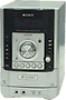
HCD-HPR90
• HCD-HPR90 is the amplifier, CD player and tuner section in CMT-HPR99XM. Photo: HCD-HPR90
Model Name Using Similar Mechanism CD Mechanism Name Base Unit Name Optical Pick-Up Block Name
NEW DLM5B BU-K6BD83S-WOD KSM-213DCP
SPECIFICATIONS...
Service Manual - Page 2

...;S PAR SONY.
2
SAFETY-RELATED COMPONENT WARNING!! A commercial leakage tester, such as described below.
HCD-HPR90/HPR99XM
Notes on chip component replacement •...service problem, perform the following safety check before releasing the set to any one of three methods.
1. Measuring the voltage drop across a resistor by any exposed metal part having a return to apply force on Set...
Service Manual - Page 3

... - Disassembly Flow 7 3-2. TEST MODE 12
5. FL Board 33 6-19. ELECTRICAL PARTS LIST 56
HCD-HPR90/HPR99XM
3 Optical Pick-Up Block 11
4. Front Panel Section 53 7-3. DISASSEMBLY 3-1. Printed Wiring Boards - Printed Wiring Board - CD Mechanical Section (DLM5B 55
8. SERVICING NOTES 4
2. CD SERVO Section 15 6-2. Schematic Diagram - Block Diagram - Block...
Service Manual - Page 4

... the optical pickup block. HCD-HPR90/HPR99XM
Ver. 1.1
SECTION 1 SERVICING NOTES
NOTES ON HANDLING THE OPTICAL PICK-UP BLOCK OR BASE UNIT
The laser diode in the optical pick-up block may suffer electrostatic break-down and also use the procedure in the printed matter which is included in the repair parts.
Ordinary soldering irons...
Service Manual - Page 5
...play time while the player is replaced by using an audio analog cord...SET ws.
3 Press /
repeatedly to operate.
1) The STANDBY indicator lights up to 20 FM and 10 AM stations.
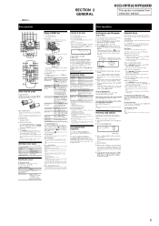
SECTION 2 GENERAL
HCD-HPR90...Connect headphones to CD function from instruction manual. To activate or check the timer...unit). Clock
The clock is turned off stereo reception. elapsed playing time of the ...
Service Manual - Page 6

...instructions...Installation costs and other sessions are not displayed;
- Activate XM Service...manually...HCD-HPR90/HPR99XM
- HPR99XM - Basic Operations
Adjusting the sound
To adjust the volume Press VOLUME +/-
To add a sound effect
To
Press
Generate a more . Set the sound effect
EQ ql on the remote (or TUNING +/- Press CD on the remote (or TUNING +/-
Notes on for stereo... replaced ...
Service Manual - Page 9

... model) (CN1205)
5 connector (CN1203)
qa MAIN board
8 flexible flat (23 core) cable (CN1309)
1 flexible flat (9 core) cable (CN1306)
7
6 two screws (B3)
3 flexible flat (15 core) cable (CN1308)
2 flexible flat (11 core) cable (CN1305)
3-5. MAIN BOARD
5 two connectors (CN32, CN604)
9 flexible flat (9 core) cable (CN1310)
4 flexible flat (19 core) cable (CN1302)
q; HCD-HPR90/HPR99XM...
Service Manual - Page 12
..." is displayed
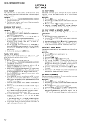
on the fluorescent indicator tube, and the ship mode is set to select "CD". 3. Press the [CD] or [FUNCTION] key ... key on the remote commander
to the customer after repair. HCD-HPR90/HPR99XM
SECTION 4 TEST MODE
COLD RESET The cold ...the [VOLUME] knob clockwise, or it decreases like 1, 2, 3 ... The model and destination are pressed, display becomes "K21". 10. Press the I /1...
Service Manual - Page 52

... model
SP : Singapore model
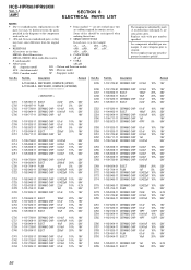
7-1.
Les composants identifiés par une marque 0 sont critiquens pour la sécurité.
HCD-HPR90/HPR99XM
Ver. 1.1
SECTION 7 EXPLODED VIEWS
NOTE: • -XX and -X mean standardized parts, so they
• Items marked "*" are not stocked since they
may have some difference from the original
are critical for routine service.
Replace only...
Service Manual - Page 56
... C761 C762 C763
C764 C765 C766 C767 C768
C769 C770 C772 C773 C774
C775 C777 C778 C779 C780
C781 C782 C783 C784 C785
C786 C787 C788 C791 C793
C794 C795
Part No. HCD-HPR90/HPR99XM
Ver. 1.1
AMP
SECTION 8 ELECTRICAL PARTS LIST
NOTE:
• Due to standardization, replacements in ohms.
uPD... : µPD...
C701 C702 C703 C704...
Service Manual - Page 69

...
SERVICE MANUAL
Ver. 1.2 2007.01
US Model
Canadian Model
HCD-HPR90/HPR99XM
E Model
Australian Model
HCD-HPR90
SUPPLEMENT-1
File this set, MAIN board has been changed in this supplement-1.
NEW/FORMER DISCRIMINATION
-MAIN Board (Component Side) - Subject: Change of new type are described in the midway of production. Printed wiring board, schematic diagram and electrical parts...
Service Manual - Page 71
...
JW1110 JW1111 JW1112
J HP A-IN BOARD CN981
(CHASSIS)
(Refer to page 31 on original service manual)
J
A CD BOARD CN102
(Refer to page 26 on original service manual)
R1623
JW1104
E Q1611 Q1613 Q1615 Q1617
D1211
EP1202
I -3 E-2
HCD-HPR90/HPR99XM
3
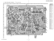
3 No. 2-1. PRINTED WIRING BOARD - HCD-HPR90/HPR99XM
1
2
3
4
5
6
7
8
9
10
11
12
13
MAIN BOARD
(Refer to page 28 on original...
Service Manual - Page 72

HCD-HPR90/HPR99XM
2-2. MAIN Section (1/3) -
(Refer to page 32 on original service manual)
CN1305 11P LED DSGX LED ...AMP SC VCC AMP SI LINE MUTE SEL B HP MUTE POWER ON/OFF ST DIN/STEREO ST CLK ST DOUT ST CE ST TUNED SEL A
R1423 10k R1424 10k R1425 ... 100
53
51
R1456 10k
R1352 100
D1202 MC2836
D1228 1N4002B D1229 1N4002B
CD DRIVER
MUTE CD XTACN
CD XRST MP3 IREQ MP3 XLAT MP3 REQ
MP3 ACK CD ...
Service Manual - Page 73

...
HCD-HPR90/HPR99XM
FM75Ω COAXIAL ANTENNA
AM
HCD-HPR90/HPR99XM
(2/3)
TO XM REG BOARD (Refer to page 24 on original service manual)
CN1205 3P
(Page 4) A1 82 A3
A4
A5
A6
A7
(Refer to page 27 on original service manual...
Q1504 RT1N141C
INVERTER
Q1505 RT1N141C
INVERTER
TUNER (FM/AM)
SUPPLIED WITH THE ASSEMBLED
BLOCK
DO/STEREO ST CLK ST DIN ST CE NC AGND R OUT +9V L OUT
CN1310 9P
B1...
Service Manual - Page 74

... 1N4002B
C1615 0.1
A+3.3V
R1693 10k
R-CH
C1636 0.001 R1643 10k
R1692 C1664
1k
∗
A-GND L-CH
∗C1614,1664 1 50V(HPR90) 10 50V(HPR99XM)
R1642 C1614
1k
∗
D1206 1N4002B
C1613 220 10V C1612 0.1
D-GND D-OUT D+3.3V
D-MUTE
MP3 CLK
CD DATA
(Refer to page 21 on original service manual)
HCD-HPR90/HPR99XM
6
6 SCHEMATIC DIAGRAM -
Sony HCD-HPR90 Reviews
We have not received any reviews for Sony yet.