
Service Manual
Page 1
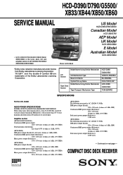
... Hz; Continued on next page - model AUDIO POWER SPECIFICATIONS POWER OUTPUT AND TOTAL HARMONIC DISTORTION: With 8 ohm loads, both channels driven, from 250 milliwatts to rated output. COMPACT DISC DECK RECEIVER MICROFILM HCD-D390/D790/G5500/ XB33/XB44/XB50/XB60 SERVICE MANUAL • HCD-D390/D790/G5500/XB33/XB44/ XB50/XB60 is the tuner, deck, CD and amplifier section in LBT-D390/D790/G5500/ XB33/XB44/XB50/XB60. "DOLBY" and the double-D symbol a are...
... Hz; Continued on next page - model AUDIO POWER SPECIFICATIONS POWER OUTPUT AND TOTAL HARMONIC DISTORTION: With 8 ohm loads, both channels driven, from 250 milliwatts to rated output. COMPACT DISC DECK RECEIVER MICROFILM HCD-D390/D790/G5500/ XB33/XB44/XB50/XB60 SERVICE MANUAL • HCD-D390/D790/G5500/XB33/XB44/ XB50/XB60 is the tuner, deck, CD and amplifier section in LBT-D390/D790/G5500/ XB33/XB44/XB50/XB60. "DOLBY" and the double-D symbol a are...
Service Manual
Page 2
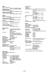
... 90 dB (HCD-XB33/XB44/XB50/XB60) CD DIGITAL OUT (square optical connector jack, rear panel) Wave length: 600 nm Output level: - 18 dBm Tape player section Recording system 4-track 2-channel stereo Frequency response (DOLBY NR OFF) 60 - 13,000 Hz (±3 dB), using a Sony TYPE I cassette 60 - 14,000 Hz (±3 dB), using a Sony TYPE II cassette Tuner section FM stereo, FM/AM superheterodyne tuner FM tuner section Tuning range (2 band model) North American model:: 87...
... 90 dB (HCD-XB33/XB44/XB50/XB60) CD DIGITAL OUT (square optical connector jack, rear panel) Wave length: 600 nm Output level: - 18 dBm Tape player section Recording system 4-track 2-channel stereo Frequency response (DOLBY NR OFF) 60 - 13,000 Hz (±3 dB), using a Sony TYPE I cassette 60 - 14,000 Hz (±3 dB), using a Sony TYPE II cassette Tuner section FM stereo, FM/AM superheterodyne tuner FM tuner section Tuning range (2 band model) North American model:: 87...

Service Manual
Page 3
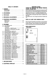
... all battery operated digital multimeters that have an accurate low-voltage scale. A battery-operated AC milliammeter. ON THE SCHEMATIC DIAGRAMS AND IN THE PARTS LIST ARE CRITICAL TO SAFE OPERATION. ATTENTION AU COMPOSANT AYANT RAPPORT À LA SÉCURITÉ! SAFETY CHECK-OUT After correcting the original service problem, perform the following caution label is located on chip component replacement • Never...
... all battery operated digital multimeters that have an accurate low-voltage scale. A battery-operated AC milliammeter. ON THE SCHEMATIC DIAGRAMS AND IN THE PARTS LIST ARE CRITICAL TO SAFE OPERATION. ATTENTION AU COMPOSANT AYANT RAPPORT À LA SÉCURITÉ! SAFETY CHECK-OUT After correcting the original service problem, perform the following caution label is located on chip component replacement • Never...
Service Manual
Page 4
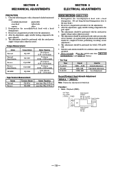
... electrostatic load, etc. PARTS No. ELECTRICAL ADJUSTMENTS DECK Section 18 Tuner Section 21 CD Section 23 6. Schematic Diagram - Deck Section 49 6-12. Printed Wiring Board - Schematic Diagram - Panel Section 61 6-19. Power Section 65 6-21. Schematic Diagram - Main Section (3/5 73 6-25. Schematic Diagram - TABLE OF CONTENTS 1. GENERAL - FRONT PANEL 5 - BACK PANEL 6 2. DISASSEMBLY 8 3. TEST MODE 16 4. DIAGRAMS 6-1. Circuit Board Location 25 6-2. Block Diagrams - CD Section 26 - Tuner Section - (AEP, UK model 27 - Tuner Section - (East European...
... electrostatic load, etc. PARTS No. ELECTRICAL ADJUSTMENTS DECK Section 18 Tuner Section 21 CD Section 23 6. Schematic Diagram - Deck Section 49 6-12. Printed Wiring Board - Schematic Diagram - Panel Section 61 6-19. Power Section 65 6-21. Schematic Diagram - Main Section (3/5 73 6-25. Schematic Diagram - TABLE OF CONTENTS 1. GENERAL - FRONT PANEL 5 - BACK PANEL 6 2. DISASSEMBLY 8 3. TEST MODE 16 4. DIAGRAMS 6-1. Circuit Board Location 25 6-2. Block Diagrams - CD Section 26 - Tuner Section - (AEP, UK model 27 - Tuner Section - (East European...

Service Manual
Page 5
button 9 TUNING + button !º PTY button (AEP, UK model) !¡ STEREO/MONO button !™ EFFECT button !£ GROOVE button !¢ FUNCTION button !∞ VOLUME knob !§ SUPER WOOFER button !¶ SUPER W MODE (D790/XB44/XB60 model) !• GEQ button !ª DECK B ª (play) button @º DECK B · (play) button @¡ DECK B p (stop) button @™ DECK B 0 (backward) button @£ DECK B ) (forward) button @¢ DECK B P (pause) button @∞ DECK B r REC button @§ H SPEED DUB button @¶ CD SYNC button @• DECK B 6 EJECT button @ª CD...
button 9 TUNING + button !º PTY button (AEP, UK model) !¡ STEREO/MONO button !™ EFFECT button !£ GROOVE button !¢ FUNCTION button !∞ VOLUME knob !§ SUPER WOOFER button !¶ SUPER W MODE (D790/XB44/XB60 model) !• GEQ button !ª DECK B ª (play) button @º DECK B · (play) button @¡ DECK B p (stop) button @™ DECK B 0 (backward) button @£ DECK B ) (forward) button @¢ DECK B P (pause) button @∞ DECK B r REC button @§ H SPEED DUB button @¶ CD SYNC button @• DECK B 6 EJECT button @ª CD...

Service Manual
Page 16
... changed over between 9kHz and 10kHz. Select the function "TUNER", and press TUNER/BAND button to turn the set OFF. 4. Use this mode when returning the set to turn the set ON. 2. Press POWER button to the customer after repair. Press PLAY MODE button and POWER button simulta- if rotating JOG knob in "+" direction, or it decreases like 1, 2, 3 ... Press POWER button to "AM 9k STEP" or "AM 10k STEP", and thus the channel step is flashing...
... changed over between 9kHz and 10kHz. Select the function "TUNER", and press TUNER/BAND button to turn the set OFF. 4. Use this mode when returning the set to turn the set ON. 2. Press POWER button to the customer after repair. Press PLAY MODE button and POWER button simulta- if rotating JOG knob in "+" direction, or it decreases like 1, 2, 3 ... Press POWER button to "AM 9k STEP" or "AM 10k STEP", and thus the channel step is flashing...

Service Manual
Page 17
... tape deck section. • If an error occurred: The aging operation stops. • If no error occurs: The aging operation continues repeatedly. 1. The aging continues unless an alarm occurred. 6. The disc tray turns to the last track. 4. TOC of tape. 9. Load a commercially available 10-minute tape into the decks A and B respectively. (If a 10-minute tape is displayed on deck A. (This button triggers the aging mode.) 6. Select the function "TAPE...
... tape deck section. • If an error occurred: The aging operation stops. • If no error occurs: The aging operation continues repeatedly. 1. The aging continues unless an alarm occurred. 6. The disc tray turns to the last track. 4. TOC of tape. 9. Load a commercially available 10-minute tape into the decks A and B respectively. (If a 10-minute tape is displayed on deck A. (This button triggers the aging mode.) 6. Select the function "TAPE...
Service Manual
Page 18
... compound to the parts adjusted. 5. SECTION 4 MECHANICAL ADJUSTMENTS SECTION 5 ELECTRICAL ADJUSTMENTS PRECAUTION 1. Clean the following parts with a head demagnetizer. 3. The adjustments should be set + - Set to test mode. (Press key switch same time GROOVE ENTER/NEXT and DISC 4 button.) • Test Tape Tape P-4-A100 WS-48B P-4-L300 Signal 10kHz, -10 dB 3kHz, 0dB 315Hz, 0dB Used for Azimuth Adjustment Tape Speed Adjustment Level Adjustment Record/Playback Head Azimuth Adjustment DECK A DECK B Note: Perform this service manual. (As a general rule...
... compound to the parts adjusted. 5. SECTION 4 MECHANICAL ADJUSTMENTS SECTION 5 ELECTRICAL ADJUSTMENTS PRECAUTION 1. Clean the following parts with a head demagnetizer. 3. The adjustments should be set + - Set to test mode. (Press key switch same time GROOVE ENTER/NEXT and DISC 4 button.) • Test Tape Tape P-4-A100 WS-48B P-4-L300 Signal 10kHz, -10 dB 3kHz, 0dB 315Hz, 0dB Used for Azimuth Adjustment Tape Speed Adjustment Level Adjustment Record/Playback Head Azimuth Adjustment DECK A DECK B Note: Perform this service manual. (As a general rule...

Service Manual
Page 19
... button in playback (REV) mode. 5. Turn the power switch on the deck B. Keep pressing the H. Take off the H. If the peaks do that adjustment within 1dB of Wow and flutter W.RMS (JIS) within 1dB Screw position R-CH peak L-CH R-CH peak peak Screw position 3. Adjust RV652 on the AUDIO board so that outputs match within adjustment level as below after setting to the test mode...
... button in playback (REV) mode. 5. Turn the power switch on the deck B. Keep pressing the H. Take off the H. If the peaks do that adjustment within 1dB of Wow and flutter W.RMS (JIS) within 1dB Screw position R-CH peak L-CH R-CH peak peak Screw position 3. Adjust RV652 on the AUDIO board so that outputs match within adjustment level as below after setting to the test mode...
Service Manual
Page 21
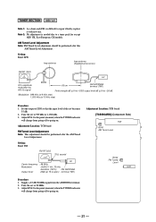
... TUNED indicator will change from the ANTENNA terminal. 2. Note 2: No adjustment is difficult to a tuner pack for except AEP, UK, East European, CIS models. Adjustment Location: TCB board FM Tuned Level Adjustment Note: This adjustment should be performed after this AM Tuned Level Adjustment. AM Tuned Level Adjustment Note: FM Tuned Level adjustment should be performed after the AM Tuned Level Adjustment. Tune the set Carrier frequency : 98 MHz Modulation : AUDIO 1 kH, 75 kHz deviation (100%) FM ANTENNA Output level...
... TUNED indicator will change from the ANTENNA terminal. 2. Note 2: No adjustment is difficult to a tuner pack for except AEP, UK, East European, CIS models. Adjustment Location: TCB board FM Tuned Level Adjustment Note: This adjustment should be performed after this AM Tuned Level Adjustment. AM Tuned Level Adjustment Note: FM Tuned Level adjustment should be performed after the AM Tuned Level Adjustment. Tune the set Carrier frequency : 98 MHz Modulation : AUDIO 1 kH, 75 kHz deviation (100%) FM ANTENNA Output level...

Service Manual
Page 23
... the waveform and check the RF signal level. • RF signal VOLT/DIV: 200 mV TIME/DIV: 500 ns level: 1.3 ± 0.3Vp-p S Curve Check BD board TP (FEO) TP (VC) oscilloscope + - Connect between A and B. Turn Power switch on . 3. Check the oscilloscope waveform (S-curve) is replaced. Adjust the focus bias adjustment when optical block is symmetrical between test point TP (FOK) and GND by an...
... the waveform and check the RF signal level. • RF signal VOLT/DIV: 200 mV TIME/DIV: 500 ns level: 1.3 ± 0.3Vp-p S Curve Check BD board TP (FEO) TP (VC) oscilloscope + - Connect between A and B. Turn Power switch on . 3. Check the oscilloscope waveform (S-curve) is replaced. Adjust the focus bias adjustment when optical block is symmetrical between test point TP (FOK) and GND by an...
Service Manual
Page 25
...CNIN 13 SEIN 23 FOK 15 DATAO 16 XLTO 17 CLKO 29 LOCK 89 90 IC103 DIGITAL SIGNAL PROCESSOR LOUT1 86 LOUT2 93 D OUT 71 E MAIN SECTION (page 31) R-CH XB33/XB44/XB50/XB60 IC391 CD DIGITAL OUT SQCK SQSQ SENS DATA XLAT CLOCK 57 XRST SCOR MDP SPOD 18 21 27 ... 9 T- BLOCK DIAGRAMS - CIRCUIT BOARD LOCATION SECTION 6 DIAGRAMS TRANS board PANEL board TCB board HEADPHONE-MIC board TC-A SW board LED board CD-A SW board DOOR SW board CD-B2 SW board MAIN board POWER AMP board TC-B SW board CD-B1 SW board CD MOTOR board MOTOR board LEAF SWITCH board BD board AUDIO board TABLE SENSOR...
...CNIN 13 SEIN 23 FOK 15 DATAO 16 XLTO 17 CLKO 29 LOCK 89 90 IC103 DIGITAL SIGNAL PROCESSOR LOUT1 86 LOUT2 93 D OUT 71 E MAIN SECTION (page 31) R-CH XB33/XB44/XB50/XB60 IC391 CD DIGITAL OUT SQCK SQSQ SENS DATA XLAT CLOCK 57 XRST SCOR MDP SPOD 18 21 27 ... 9 T- BLOCK DIAGRAMS - CIRCUIT BOARD LOCATION SECTION 6 DIAGRAMS TRANS board PANEL board TCB board HEADPHONE-MIC board TC-A SW board LED board CD-A SW board DOOR SW board CD-B2 SW board MAIN board POWER AMP board TC-B SW board CD-B1 SW board CD MOTOR board MOTOR board LEAF SWITCH board BD board AUDIO board TABLE SENSOR...

Service Manual
Page 26
TUNER SECTION - (AEP, UK model) TM1 ANTENNA FM 75Ω COAXIAL AM ST +10V Q5 ANT IN FE1 FM FRONT END IF OUT CF1 10.7MHz IF AMP Q1, 2 CF2 10.7MHz IF AMP Q3, 4 CF3 10.7MHz 1 FM IN FM DET OUT 23 22 MPX IN OUT L 21 OUT R 20 AMP LPF 19 AMP... DET AM DET 24 OUT AM TUNED LEVEL STEREO 7 70 TUNED 6 69 OSC.BUFF FM SD ...STEREO TUNED MUTE B MAIN SECTION (Page 32) MW AM OSC FM VCO STOP FM/AM IF XIN XOUT X21 4.5MHz 11 14 7 2 12 1 24 CE 3 DI 4 CL 5 DO 6 68 ST-CE 67 COM-DIN 65 COM-CLK 66 COM-DATA • R CH: Same as L ch • SIGNAL PATH : FM : AM - 27 - - 28 - HCD-D390...
TUNER SECTION - (AEP, UK model) TM1 ANTENNA FM 75Ω COAXIAL AM ST +10V Q5 ANT IN FE1 FM FRONT END IF OUT CF1 10.7MHz IF AMP Q1, 2 CF2 10.7MHz IF AMP Q3, 4 CF3 10.7MHz 1 FM IN FM DET OUT 23 22 MPX IN OUT L 21 OUT R 20 AMP LPF 19 AMP... DET AM DET 24 OUT AM TUNED LEVEL STEREO 7 70 TUNED 6 69 OSC.BUFF FM SD ...STEREO TUNED MUTE B MAIN SECTION (Page 32) MW AM OSC FM VCO STOP FM/AM IF XIN XOUT X21 4.5MHz 11 14 7 2 12 1 24 CE 3 DI 4 CL 5 DO 6 68 ST-CE 67 COM-DIN 65 COM-CLK 66 COM-DATA • R CH: Same as L ch • SIGNAL PATH : FM : AM - 27 - - 28 - HCD-D390...

Service Manual
Page 27
- TUNER SECTION - (East European, CIS model) HCD-D390/D790/G5500/XB33/XB44/XB50/XB60 TM1 ANTENNA FM 75Ω COAXIAL AM ST +10V Q5 ANT IN FE1 FM FRONT END IF OUT CF1 10.7MHz IF AMP Q1-4 CF3 10.7MHz 1 FM IN FM DET OUT 23 VT FE2 MW/LW FRONTEND 6 5 3 2 26 25 24 23 22... L AMP OUT 17 L 3 POUT R OUT 6 R CH RV1701 SUB CARRIER LEVEL 20 SUB IN 18 17 TP1702 RV1702 VCO 10 9 CE 3 DI 4 CL 5 DO 6 MON VCO ST IND VCO STOP R OUT 4 CA 9 11 R CH D1701 D1702 SWITCH Q1701 SWITCH Q1702 SWITCH Q1703 D1703 70 69 72 D1704 68 67 65 66 A ST-L MAIN SECTION (Page 31) STEREO TUNED MUTE...
- TUNER SECTION - (East European, CIS model) HCD-D390/D790/G5500/XB33/XB44/XB50/XB60 TM1 ANTENNA FM 75Ω COAXIAL AM ST +10V Q5 ANT IN FE1 FM FRONT END IF OUT CF1 10.7MHz IF AMP Q1-4 CF3 10.7MHz 1 FM IN FM DET OUT 23 VT FE2 MW/LW FRONTEND 6 5 3 2 26 25 24 23 22... L AMP OUT 17 L 3 POUT R OUT 6 R CH RV1701 SUB CARRIER LEVEL 20 SUB IN 18 17 TP1702 RV1702 VCO 10 9 CE 3 DI 4 CL 5 DO 6 MON VCO ST IND VCO STOP R OUT 4 CA 9 11 R CH D1701 D1702 SWITCH Q1701 SWITCH Q1702 SWITCH Q1703 D1703 70 69 72 D1704 68 67 65 66 A ST-L MAIN SECTION (Page 31) STEREO TUNED MUTE...

Service Manual
Page 28
J761 MIC J101 (1 / 3) PHONO CD SECTION E (page 26) TUNER SECTION A (page 28,30) J101 (2 / 3) VIDEO (AUDIO) IN R-CH IC101 IC760 (1 / 2) RV706 IC760 (2 / 2) MIC AMP MIC LEVEL MIC AMP PHONO AMP IC102 INPUT SELECTOR 15 69 65 14 13 71 11 A 28 B MICON 12 3 R-CH 29 C 30 INTERFACE 4 10 A 5 9B 2 6C 32 33 34 Q101,Q102,Q103 INPUT CHANGE XB33/XB44/XB50/XB60 J101(3/3) VIDEO (AUDIO) OUT IC231 SPEANA MIX...
J761 MIC J101 (1 / 3) PHONO CD SECTION E (page 26) TUNER SECTION A (page 28,30) J101 (2 / 3) VIDEO (AUDIO) IN R-CH IC101 IC760 (1 / 2) RV706 IC760 (2 / 2) MIC AMP MIC LEVEL MIC AMP PHONO AMP IC102 INPUT SELECTOR 15 69 65 14 13 71 11 A 28 B MICON 12 3 R-CH 29 C 30 INTERFACE 4 10 A 5 9B 2 6C 32 33 34 Q101,Q102,Q103 INPUT CHANGE XB33/XB44/XB50/XB60 J101(3/3) VIDEO (AUDIO) OUT IC231 SPEANA MIX...

Service Manual
Page 29
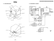
...; Waveforms are critical for repair. • Voltages and waveforms are dc with respect to ground under no-signal (detuned) conditions. • Voltages are taken with a oscilloscope. • Circled numbers refer to waveforms. • Signal path. are taken with a VOM (Input impedance 10 MΩ). HCD-D390/D790/G5500/XB33/XB44/XB50/XB60 - PANEL SECTION - 1 5 IC101 #£ (PLAY MODE) IC103 ^º (XPCK) 9 IC601...
...; Waveforms are critical for repair. • Voltages and waveforms are dc with respect to ground under no-signal (detuned) conditions. • Voltages are taken with a oscilloscope. • Circled numbers refer to waveforms. • Signal path. are taken with a VOM (Input impedance 10 MΩ). HCD-D390/D790/G5500/XB33/XB44/XB50/XB60 - PANEL SECTION - 1 5 IC101 #£ (PLAY MODE) IC103 ^º (XPCK) 9 IC601...
Service Manual
Page 48
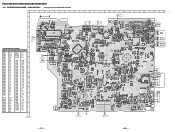
... R151 R102 C102 XB50/XB60 JW151 C101 OUT 5V GND XB33/XB34/ XB50/XB60 IC391 CD DIGITAL OUT EXCEPT XB50/XB60 D390/D790/G5500 R J101 PHONO L R101 JW101 R VIDEO/MD (AUDIO) IN L R VIDEO/MD (AUDIO) OUT L EXCEPT D390/D790/G5500 C255 C251 C262 24 25 D790/XB44/ XB50/XB60 B C E EXCEPT D790/XB44... XB44 FAN D790/XB33/XB50/XB60 TM132 SURROUND SPEAKER R+ L+ R- BCE EXCEPT XB50/XB60 XB50/XB60 1-663-999- 13 (31) F TRANS BOARD CN901 (Page 63, 64) (CHASSIS) G POWER AMP BOARD CN801 (Page 63) - 67 - - 68 - HCD-D390/D790/G5500/XB33/XB44/XB50/XB60 6-21. Location Ref. PRINTED WIRING BOARD -
... R151 R102 C102 XB50/XB60 JW151 C101 OUT 5V GND XB33/XB34/ XB50/XB60 IC391 CD DIGITAL OUT EXCEPT XB50/XB60 D390/D790/G5500 R J101 PHONO L R101 JW101 R VIDEO/MD (AUDIO) IN L R VIDEO/MD (AUDIO) OUT L EXCEPT D390/D790/G5500 C255 C251 C262 24 25 D790/XB44/ XB50/XB60 B C E EXCEPT D790/XB44... XB44 FAN D790/XB33/XB50/XB60 TM132 SURROUND SPEAKER R+ L+ R- BCE EXCEPT XB50/XB60 XB50/XB60 1-663-999- 13 (31) F TRANS BOARD CN901 (Page 63, 64) (CHASSIS) G POWER AMP BOARD CN801 (Page 63) - 67 - - 68 - HCD-D390/D790/G5500/XB33/XB44/XB50/XB60 6-21. Location Ref. PRINTED WIRING BOARD -

Service Manual
Page 58
... I Function Line mute signal output DBFB H/L select signal output Latch signal output for IC201 (62427) Not used Front speaker relay control output Not used Connected ground X'tal (5MHz) Power supply (+5V) X'tal (32.768 KHz) Reset signal input Connected ground Sub code data request signal output Software test port Back up signal input RDS signal input RDS data input Power supply (+5V) Analog reference voltage input CD adjust point port A Deck reel pulse detector B Deck reel pulse detector Half detector signal input Connected ground Version select signal input Connected ground DEMO H/L select...
... I Function Line mute signal output DBFB H/L select signal output Latch signal output for IC201 (62427) Not used Front speaker relay control output Not used Connected ground X'tal (5MHz) Power supply (+5V) X'tal (32.768 KHz) Reset signal input Connected ground Sub code data request signal output Software test port Back up signal input RDS signal input RDS data input Power supply (+5V) Analog reference voltage input CD adjust point port A Deck reel pulse detector B Deck reel pulse detector Half detector signal input Connected ground Version select signal input Connected ground DEMO H/L select...

Service Manual
Page 59
.../OFF O NR ON/OFF signal output 92 R/P-PASS I REC/PB/PASS selection output 93 TC-MUTE O TC mute ON/OFF selection output 94 A-PLAY-SW I Deck A play detect 95 B-PLAY-SW I Deck B play detect 96 TC-RELAY O REC/PB head selection output for IC602 97 A-HALF I Stereo detection for tuner 70 STEREO I Deck A cassette detect 98 POWER O POWER ON/OFF signal output 99 SW-F-CHG O Super woofer mode signal output 100 STK-MUTE O Power amp ON/OFF signal output - 85 -
.../OFF O NR ON/OFF signal output 92 R/P-PASS I REC/PB/PASS selection output 93 TC-MUTE O TC mute ON/OFF selection output 94 A-PLAY-SW I Deck A play detect 95 B-PLAY-SW I Deck B play detect 96 TC-RELAY O REC/PB head selection output for IC602 97 A-HALF I Stereo detection for tuner 70 STEREO I Deck A cassette detect 98 POWER O POWER ON/OFF signal output 99 SW-F-CHG O Super woofer mode signal output 100 STK-MUTE O Power amp ON/OFF signal output - 85 -
Service Manual
Page 70
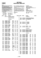
...181;PD... used on the set. • -XX, -X mean standardized parts, so they are seldom required for routine service. Description <...components The components identified by mark ! Description A-2007-131-A AUDIO BOARD, COMPLETE including MOTOR BOARD) < CAPACITOR > Remarks Ref. No. * Part No. or dotted line with part number specified. AUDIO SECTION 8 ELECTRICAL PARTS LIST NOTE: When indicating parts by reference number, please include the board name. • Due to standardization, replacements in the parts list may have some difference from the parts specified in ohms...
...181;PD... used on the set. • -XX, -X mean standardized parts, so they are seldom required for routine service. Description <...components The components identified by mark ! Description A-2007-131-A AUDIO BOARD, COMPLETE including MOTOR BOARD) < CAPACITOR > Remarks Ref. No. * Part No. or dotted line with part number specified. AUDIO SECTION 8 ELECTRICAL PARTS LIST NOTE: When indicating parts by reference number, please include the board name. • Due to standardization, replacements in the parts list may have some difference from the parts specified in ohms...


