Service Manual
Page 18
... +] buttons simultane- ously and hold down until "DEMO ON" or "DEMO OFF" displayed on . 2. To release from this mode is activated, the disc will be displayed on fluorescent indica- Each time the [VOLUME +] button on the set to the model information display. "K 0" value increases whenever ... to turn the power on . 2. Main Functions • ErrorLog display Display the error log. HBD-E370/E470/E570/E870/T57 SECTION 3 TEST MODE COLD RESET The cold reset clears data except BD/DVD data stored in the RAM to turn the power on the remote commander, the state of D.C.A.C. ...
... +] buttons simultane- ously and hold down until "DEMO ON" or "DEMO OFF" displayed on . 2. To release from this mode is activated, the disc will be displayed on fluorescent indica- Each time the [VOLUME +] button on the set to the model information display. "K 0" value increases whenever ... to turn the power on . 2. Main Functions • ErrorLog display Display the error log. HBD-E370/E470/E570/E870/T57 SECTION 3 TEST MODE COLD RESET The cold reset clears data except BD/DVD data stored in the RAM to turn the power on the remote commander, the state of D.C.A.C. ...
Service Manual
Page 22
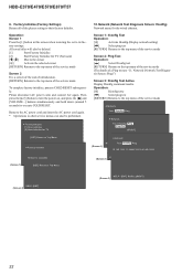
HBD-E370/E470/E570/E870/T57 9. Factory Initialize [1] Start Initialize [2] Start Initialize for the wired ethernet. Screen 1: Ifconfig Test Operation: [3] Activate Ifconfig (Display network setting) [,] Select ping test [RETURN] Returns to the top menu of the service mode To complete factory initialize, process COLD RESET...and insert the AC power cord again. * Operations in this screen when restoring the set to execute COLD RESET. Network (Network Test Diagnosis Screen: Ifconfig) Network menu for TV 10. Factory Initialize (Factory Settings) ...
HBD-E370/E470/E570/E870/T57 9. Factory Initialize [1] Start Initialize [2] Start Initialize for the wired ethernet. Screen 1: Ifconfig Test Operation: [3] Activate Ifconfig (Display network setting) [,] Select ping test [RETURN] Returns to the top menu of the service mode To complete factory initialize, process COLD RESET...and insert the AC power cord again. * Operations in this screen when restoring the set to execute COLD RESET. Network (Network Test Diagnosis Screen: Ifconfig) Network menu for TV 10. Factory Initialize (Factory Settings) ...
Service Manual
Page 33
...RECEIVER IC803 4 SIRCS_IN D506 S700 - 705, 750 3 D508 19 KEY_INT KEY0 - GR10 32 GR11 VEE T800 DC/DC CONVERTER TRANSFORMER DIN 7 CLK 8 STB 9 D803, 804 RECT OSC Q803 5 FL_DOUT 7 FL_CLK 3 FL_CS AC_CUT 20 RESET 12 RESET SWITCH Q504 VOLTAGE DETECTOR IC506 VOLTAGE DETECTOR IC507 RESET SIGNAL GENERATOR IC503 E +14V E +6V E -9V E +4V HBD-E370/E470/E570...POWER CONTROL IC921 3 Vcc/DVP 6 BD 5 FB/CLP 1D RECT D901 TH901 LINE F901 FILTER LF901, 902 (AC IN) HBD-E370/E470/E570/E870/T57 33 33 SG16 10 GRID DRIVE Q804 GR1 - 5-6. PANEL, POWER SUPPLY Section - KEY2 KEY0 KEY2 97, 95...
...RECEIVER IC803 4 SIRCS_IN D506 S700 - 705, 750 3 D508 19 KEY_INT KEY0 - GR10 32 GR11 VEE T800 DC/DC CONVERTER TRANSFORMER DIN 7 CLK 8 STB 9 D803, 804 RECT OSC Q803 5 FL_DOUT 7 FL_CLK 3 FL_CS AC_CUT 20 RESET 12 RESET SWITCH Q504 VOLTAGE DETECTOR IC506 VOLTAGE DETECTOR IC507 RESET SIGNAL GENERATOR IC503 E +14V E +6V E -9V E +4V HBD-E370/E470/E570...POWER CONTROL IC921 3 Vcc/DVP 6 BD 5 FB/CLP 1D RECT D901 TH901 LINE F901 FILTER LF901, 902 (AC IN) HBD-E370/E470/E570/E870/T57 33 33 SG16 10 GRID DRIVE Q804 GR1 - 5-6. PANEL, POWER SUPPLY Section - KEY2 KEY0 KEY2 97, 95...

Service Manual
Page 54
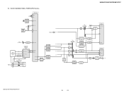
...R589 100 RB504 100 CN510 9P JL578 JL591 JL592 JL594 JL596 JL597 JL599 JL601 1 D-GND 2 TXD1 3 RTS1 4 3.3V 5 CLK1 6 RXD1 7 CNVSS 8 RESET 9 D-GND (NC) DIAG JL623 EN FAN_CONT FAN_ON DC-DET OVF2 OVF1 LAT3 LAT2 LAT1 SHIFT_DIR_CL SCDT_DIR_DI SOFT_MUTE NS_INIT NSP_MUTE A.CAL_OUT D3070 MA2J1110GLS0 R651 1k JL624...(Page 56) 56 MAIN BOARD (4/5) (Page 57) 57 MAIN BOARD (5/5) (Page 58) 10 9 8 7 51 (Page 55) 6 5 MAIN BOARD 4 (2/5) 3 2 1 C528 0.1 BD_IF_REQ BD_IF_START RESET CNVSS HBD-E370/E470/E570/E870/T57 54 54 HBD-E370/E470/E570/E870/T57 5-26. SCHEMATIC DIAGRAM -
...R589 100 RB504 100 CN510 9P JL578 JL591 JL592 JL594 JL596 JL597 JL599 JL601 1 D-GND 2 TXD1 3 RTS1 4 3.3V 5 CLK1 6 RXD1 7 CNVSS 8 RESET 9 D-GND (NC) DIAG JL623 EN FAN_CONT FAN_ON DC-DET OVF2 OVF1 LAT3 LAT2 LAT1 SHIFT_DIR_CL SCDT_DIR_DI SOFT_MUTE NS_INIT NSP_MUTE A.CAL_OUT D3070 MA2J1110GLS0 R651 1k JL624...(Page 56) 56 MAIN BOARD (4/5) (Page 57) 57 MAIN BOARD (5/5) (Page 58) 10 9 8 7 51 (Page 55) 6 5 MAIN BOARD 4 (2/5) 3 2 1 C528 0.1 BD_IF_REQ BD_IF_START RESET CNVSS HBD-E370/E470/E570/E870/T57 54 54 HBD-E370/E470/E570/E870/T57 5-26. SCHEMATIC DIAGRAM -

Service Manual
Page 59
...CL301 3 CL302 2 CL303 1 Q300, 301 B+ SWITCH R303 47k Q301 2SB1690KT146 4.2 0 R302 470 4.2 R301 470 Q300 RT1N441M-TP-1 0 3.3 GPIO2 I2C-SDA ADC-SEL I2C-SCL RESET SD3 P_CONT_S-AIR SD2 CN300 15P CL305 1 CL307 2 CL306 3 CL309 4 CL308 5 CL311 6 CL304 7 CL312 8 GND 9 SD1 10 CL313 GND 11 LRCK 12 GND 13 BCK... 14 CL315 CL318 CL317 GND 15 R300 470 HBD-E370/E470/E570/E870/T57 4 5 6 R311 10k R320 0 R307 10k R308 10k R309 10k CL355 CL352 CN303 30P EZW-T100 (CHASSIS) CL325 CL326 CL328 CL329 CL334 ...
...CL301 3 CL302 2 CL303 1 Q300, 301 B+ SWITCH R303 47k Q301 2SB1690KT146 4.2 0 R302 470 4.2 R301 470 Q300 RT1N441M-TP-1 0 3.3 GPIO2 I2C-SDA ADC-SEL I2C-SCL RESET SD3 P_CONT_S-AIR SD2 CN300 15P CL305 1 CL307 2 CL306 3 CL309 4 CL308 5 CL311 6 CL304 7 CL312 8 GND 9 SD1 10 CL313 GND 11 LRCK 12 GND 13 BCK... 14 CL315 CL318 CL317 GND 15 R300 470 HBD-E370/E470/E570/E870/T57 4 5 6 R311 10k R320 0 R307 10k R308 10k R309 10k CL355 CL352 CN303 30P EZW-T100 (CHASSIS) CL325 CL326 CL328 CL329 CL334 ...

Service Manual
Page 69
... SWITCH LED CONTROL CIRCUIT LATCH CIRCUIT CURRENT SWITCH CONTROL CIRCUIT CURRENT SWITCH SWITCHIG REGURATOR INTERNAL CONTROL SWITCHING REGULATOR SWITCHIG REGURATOR VOLTAGE RESET CONTROL STP1 CONTROL CIRCUIT STP2 CONTROL CIRCUIT SWITCHING REGULATOR PRE-DRIVER A5V POWER MOS FET 30 LATCH_RSOUT 29 LATCH_XRSOUT 28 CSWI...P5V_SW 20 FB1PXV 19 STP218 STP2+ COLLIMATOR END DETECTION POWER MONITOR VCO TSD REFERENCE PRE-DRIVER A5V POWER MOS FET 17 STP116 STP1+ 69 HBD-E370/E470/E570/E870/T57 IC1003 MM1797CVBE V IN 1 110k: BIAS 4dB VCC1 2 PR IN 3 110k: BIAS 4dB BIAS 4 VREF PB IN 5...
... SWITCH LED CONTROL CIRCUIT LATCH CIRCUIT CURRENT SWITCH CONTROL CIRCUIT CURRENT SWITCH SWITCHIG REGURATOR INTERNAL CONTROL SWITCHING REGULATOR SWITCHIG REGURATOR VOLTAGE RESET CONTROL STP1 CONTROL CIRCUIT STP2 CONTROL CIRCUIT SWITCHING REGULATOR PRE-DRIVER A5V POWER MOS FET 30 LATCH_RSOUT 29 LATCH_XRSOUT 28 CSWI...P5V_SW 20 FB1PXV 19 STP218 STP2+ COLLIMATOR END DETECTION POWER MONITOR VCO TSD REFERENCE PRE-DRIVER A5V POWER MOS FET 17 STP116 STP1+ 69 HBD-E370/E470/E570/E870/T57 IC1003 MM1797CVBE V IN 1 110k: BIAS 4dB VCC1 2 PR IN 3 110k: BIAS 4dB BIAS 4 VREF PB IN 5...

Service Manual
Page 73
...GND_C 29 GND_D BTL/P BTL-CONFIGURATION PULLDOWN RESISTORS 28 OUT_D 27 PVDD_D 26 PVDD_D 25 NC 24 BST_D 23 GVDD_D 73 HBD-E370/E470/E570/E870/T57 IC3011 SI-3010KM-TLS VC 1 VIN 2 GND 3 VOUT 4 ADJ 5 TSD - + REF IC3050 ...MM3404A18URE CE 1 GND 2 BIAS VOLTAGE REFERENCE - + CURRENT LIMIT 4 VDD 3 VOUT IC3100, 3200, 3400 CXD9981TN GVDD_B 1 /OTW 2 NC 3 NC 4 /SD 5 PWM_A 6 /RESET_AB 7 PWM_B 8 INTERNAL PULLUP RESISTORS TO VREG PROATNEDCTION I/O LOGIC UNDER VOLTAGE PROTECTION 4 4 POWER ON RESET...
...GND_C 29 GND_D BTL/P BTL-CONFIGURATION PULLDOWN RESISTORS 28 OUT_D 27 PVDD_D 26 PVDD_D 25 NC 24 BST_D 23 GVDD_D 73 HBD-E370/E470/E570/E870/T57 IC3011 SI-3010KM-TLS VC 1 VIN 2 GND 3 VOUT 4 ADJ 5 TSD - + REF IC3050 ...MM3404A18URE CE 1 GND 2 BIAS VOLTAGE REFERENCE - + CURRENT LIMIT 4 VDD 3 VOUT IC3100, 3200, 3400 CXD9981TN GVDD_B 1 /OTW 2 NC 3 NC 4 /SD 5 PWM_A 6 /RESET_AB 7 PWM_B 8 INTERNAL PULLUP RESISTORS TO VREG PROATNEDCTION I/O LOGIC UNDER VOLTAGE PROTECTION 4 4 POWER ON RESET...
Service Manual
Page 76
... - Not used O Reset signal output to the HDMI ARC OUT connector - Not used - Not used - Not used I Receive data input from the ethernet interface I Receive data input from the ethernet interface I Receive clock signal input from the digital audio interface receiver O Digital audio data output to the audio section - Not used - HBD-E370/E470/E570/E870/T57...
... - Not used O Reset signal output to the HDMI ARC OUT connector - Not used - Not used - Not used I Receive data input from the ethernet interface I Receive data input from the ethernet interface I Receive clock signal input from the digital audio interface receiver O Digital audio data output to the audio section - Not used - HBD-E370/E470/E570/E870/T57...

Service Manual
Page 77
HBD-E370/E470/E570/E870/T57 Pin No. Not used I Interrupt signal input from the digital audio interface receiver - Not used O Clock signal output terminal for the front-end serial flash - Not used I Serial data transfer clock signal input terminal for...TMDS data (positive) output to the HDMI ARC OUT connector O TMDS clock signal (positive) output to the HDMI ARC OUT connector O Not used I System reset signal input from the system controller O Transmit error signal output to the ethernet interface O Transmit data output to the HDMI ARC OUT connector O Video signal...
HBD-E370/E470/E570/E870/T57 Pin No. Not used I Interrupt signal input from the digital audio interface receiver - Not used O Clock signal output terminal for the front-end serial flash - Not used I Serial data transfer clock signal input terminal for...TMDS data (positive) output to the HDMI ARC OUT connector O TMDS clock signal (positive) output to the HDMI ARC OUT connector O Not used I System reset signal input from the system controller O Transmit error signal output to the ethernet interface O Transmit data output to the HDMI ARC OUT connector O Video signal...

Service Manual
Page 79
HBD-E370/E470/E570/E870/T57 Pin No. Power supply terminal (+3.3V) - Not used - Power supply terminal (+3.3V) O Read enable signal output to the NAND flash O Chip enable ... FE_VWDC2O FE_AUX1 FE_RSTI FE_MVDDO FE_MVDDO NFREN NFCEN NFD7 B_REXTDN FE_INB FE_TRINC FE_VFVREF FE_DVDD33O FE_DVDD33O FE_DVDD33O VCC3IO_2 DVSS DVSS B_RCLK1 B_RCLK1B FE_INA FE_TRINA FE_VWDC1O FE_AVDD12_1 FE_DVDD33O I Reset signal input terminal for the front-end serial flash I /O Two-way data bus with the NAND flash - Ground terminal - Power supply terminal (+3.3V...
HBD-E370/E470/E570/E870/T57 Pin No. Power supply terminal (+3.3V) - Not used - Power supply terminal (+3.3V) O Read enable signal output to the NAND flash O Chip enable ... FE_VWDC2O FE_AUX1 FE_RSTI FE_MVDDO FE_MVDDO NFREN NFCEN NFD7 B_REXTDN FE_INB FE_TRINC FE_VFVREF FE_DVDD33O FE_DVDD33O FE_DVDD33O VCC3IO_2 DVSS DVSS B_RCLK1 B_RCLK1B FE_INA FE_TRINA FE_VWDC1O FE_AVDD12_1 FE_DVDD33O I Reset signal input terminal for the front-end serial flash I /O Two-way data bus with the NAND flash - Ground terminal - Power supply terminal (+3.3V...

Service Manual
Page 84
HBD-E370/E470/E570/E870/T57 Pin No. Power supply terminal (+3.3V) - Power supply terminal (+1.1V) - Not used - Not used - Ground terminal - Ground terminal - Power supply terminal (+1.... to the SD-RAM - Power supply terminal (+1.2V) - Ground terminal - Power supply terminal (+1.1V) - Power supply terminal (+1.2V) - Power supply terminal (+1.2V) I System reset signal input from the system controller - Power supply terminal (+1.2V) - Power supply terminal (+1.1V) - Power supply terminal (+3.3V) - Power supply terminal (+1.8V) I SATA channel...
HBD-E370/E470/E570/E870/T57 Pin No. Power supply terminal (+3.3V) - Power supply terminal (+1.1V) - Not used - Not used - Ground terminal - Ground terminal - Power supply terminal (+1.... to the SD-RAM - Power supply terminal (+1.2V) - Ground terminal - Power supply terminal (+1.1V) - Power supply terminal (+1.2V) - Power supply terminal (+1.2V) I System reset signal input from the system controller - Power supply terminal (+1.2V) - Power supply terminal (+1.1V) - Power supply terminal (+3.3V) - Power supply terminal (+1.8V) I SATA channel...

Service Manual
Page 88
... (25 MHz) O Receive data output to the BD decoder O Receive data valid signal output to the BD decoder O Receive clock signal output to the BD decoder O Receive error signal output to the... - Power supply terminal (+3.3V) (analog system) O Collision detect signal output to the BD decoder 88 HBD-E370/E470/E570/E870/T57 MB-134 BOARD IC1201 LAN8700C-AEZG-CTI (ETHERNET INTERFACE) Pin No. 1 2 3 4 ...sense signal output to the BD decoder I/O Two-way data bus with the BD decoder I Reset signal input from the system controller I Reference resistor connection terminal - Not used - Power ...
... (25 MHz) O Receive data output to the BD decoder O Receive data valid signal output to the BD decoder O Receive clock signal output to the BD decoder O Receive error signal output to the... - Power supply terminal (+3.3V) (analog system) O Collision detect signal output to the BD decoder 88 HBD-E370/E470/E570/E870/T57 MB-134 BOARD IC1201 LAN8700C-AEZG-CTI (ETHERNET INTERFACE) Pin No. 1 2 3 4 ...sense signal output to the BD decoder I/O Two-way data bus with the BD decoder I Reset signal input from the system controller I Reference resistor connection terminal - Not used - Power ...

Service Manual
Page 89
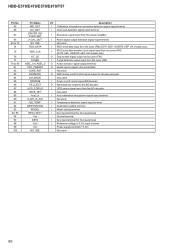
... - Not used S-AIR_GPIO2 I Interrupt signal input from the remote control receiver FL_DOUT O Serial data output to the fluorescent indicator tube driver CEC_RX_IN - Ground terminal Xin I System reset signal input from the reset signal generator Xout O Main system clock output terminal (6 MHz) Vss... input terminal Xcin I Sub system clock input terminal Not used Xcout O Sub system clock output terminal Not used RESET I Main system clock input terminal (6 MHz) Vcc - HBD-E370/E470/E570/E870/T57 MAIN BOARD IC501 R5F364AMDFA (SYSTEM CONTROLLER) Pin No. 1 2 3 4 5 6 7 8 9...
... - Not used S-AIR_GPIO2 I Interrupt signal input from the remote control receiver FL_DOUT O Serial data output to the fluorescent indicator tube driver CEC_RX_IN - Ground terminal Xin I System reset signal input from the reset signal generator Xout O Main system clock output terminal (6 MHz) Vss... input terminal Xcin I Sub system clock input terminal Not used Xcout O Sub system clock output terminal Not used RESET I Main system clock input terminal (6 MHz) Vcc - HBD-E370/E470/E570/E870/T57 MAIN BOARD IC501 R5F364AMDFA (SYSTEM CONTROLLER) Pin No. 1 2 3 4 5 6 7 8 9...
Service Manual
Page 90
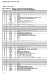
Ground terminal I Key input terminal for front panel keys - HBD-E370/E470/E570/E870/T57 Pin No. 65 66 67 68 69 to 73 74 75 76 77 78 to 80 81 82 83 84 85 86 87 ... input terminal I Shut down signal input from the power amplifier I UPG status signal input from the tuner (FM) O Audio selection signal output terminal O Reset signal output to the BD decoder I AUdio signal output detection signal input terminal - Power supply terminal (+3.3V) - Not used I Temperature detection signal input terminal I Destination...
Ground terminal I Key input terminal for front panel keys - HBD-E370/E470/E570/E870/T57 Pin No. 65 66 67 68 69 to 73 74 75 76 77 78 to 80 81 82 83 84 85 86 87 ... input terminal I Shut down signal input from the power amplifier I UPG status signal input from the tuner (FM) O Audio selection signal output terminal O Reset signal output to the BD decoder I AUdio signal output detection signal input terminal - Power supply terminal (+3.3V) - Not used I Temperature detection signal input terminal I Destination...


