Service Manual
Page 1
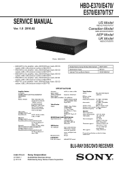
..., USB, LAN and tuner section in ) (w/h/d) incl. BLU-RAY DISC/DVD RECEIVER 9-889-770-01 2010B05-1 © 2010.02 Sony Corporation Audio&Video Business Group Published by Sony Techno Create Corporation models: POWER OUTPUT AND TOTAL HARMONIC DISTORTION: (FTC) Front L + Front R: With 3 ohms loads, both channels driven, from 250 milli watts to rated output. projecting parts 4.8 kg (10 lb 10 oz) Design and specifications are subject to 48 kHz), Dolby Digital...
..., USB, LAN and tuner section in ) (w/h/d) incl. BLU-RAY DISC/DVD RECEIVER 9-889-770-01 2010B05-1 © 2010.02 Sony Corporation Audio&Video Business Group Published by Sony Techno Create Corporation models: POWER OUTPUT AND TOTAL HARMONIC DISTORTION: (FTC) Front L + Front R: With 3 ohms loads, both channels driven, from 250 milli watts to rated output. projecting parts 4.8 kg (10 lb 10 oz) Design and specifications are subject to 48 kHz), Dolby Digital...
Service Manual
Page 2
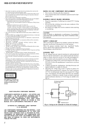
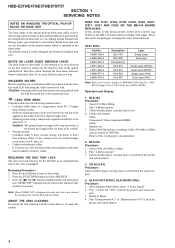
... of HDMI Licensing LLC. • Java and all battery operated digital multimeters that have an accurate low-voltage scale. Gracenote is the industry standard in hazardous radiation exposure. LEAKAGE TEST The AC leakage from Dolby Laboratories. Follow the manufacturers' instructions to check AC leakage. HBD-E370/E470/E570/E870/T57 • This product incorporates copyright protection technology that is protected by...
... of HDMI Licensing LLC. • Java and all battery operated digital multimeters that have an accurate low-voltage scale. Gracenote is the industry standard in hazardous radiation exposure. LEAKAGE TEST The AC leakage from Dolby Laboratories. Follow the manufacturers' instructions to check AC leakage. HBD-E370/E470/E570/E870/T57 • This product incorporates copyright protection technology that is protected by...
Service Manual
Page 3
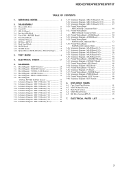
... 60 5-34. Schematic Diagram - KEY Section 66 5-40. Printed Wiring Board - Printed Wiring Board - CONNECT Board 59 5-32. POWER Board 64 5-38. KEY Section 66 6. MB-134 Board (7/13 41 5-14. TEST MODE 18 4. Printed Wiring Board - MEMORY Section 29 5-3. SERVICING NOTES 4 2. Block Diagram - DISASSEMBLY 2-1. CONNECT Board 14 2-8. BD Drive (BPX-5 15 2-9. AUDIO Board 16 2-12. DIAGRAMS 5-1. Block Diagram - PANEL, POWER SUPPLY Section 33 5-7. Schematic Diagram - Schematic Diagram - AUDIO Board 51 5-24...
... 60 5-34. Schematic Diagram - KEY Section 66 5-40. Printed Wiring Board - Printed Wiring Board - CONNECT Board 59 5-32. POWER Board 64 5-38. KEY Section 66 6. MB-134 Board (7/13 41 5-14. TEST MODE 18 4. Printed Wiring Board - MEMORY Section 29 5-3. SERVICING NOTES 4 2. Block Diagram - DISASSEMBLY 2-1. CONNECT Board 14 2-8. BD Drive (BPX-5 15 2-9. AUDIO Board 16 2-12. DIAGRAMS 5-1. Block Diagram - PANEL, POWER SUPPLY Section 33 5-7. Schematic Diagram - Schematic Diagram - AUDIO Board 51 5-24...
Service Manual
Page 4
... generated by the objective lens in the repair parts. Play "4.Motion picture". 3. Audio: Speaker out. * When 1080/24p monitor is equipped. put). 3. Return to select "BD/DVD". 3. Play "Demonstration 4:3" or "Demonstration 16:9" (Check the picture and sound output). 4 Note: When "DEMO ON" is displayed, the disc tray lock is more than 30 cm away from the objective lens. TEST DISC Part No. Select 1080i (59.94Hz or 50Hz). 2. Ordinary...
... generated by the objective lens in the repair parts. Play "4.Motion picture". 3. Audio: Speaker out. * When 1080/24p monitor is equipped. put). 3. Return to select "BD/DVD". 3. Play "Demonstration 4:3" or "Demonstration 16:9" (Check the picture and sound output). 4 Note: When "DEMO ON" is displayed, the disc tray lock is more than 30 cm away from the objective lens. TEST DISC Part No. Select 1080i (59.94Hz or 50Hz). 2. Ordinary...
Service Manual
Page 5
... by service headquarters. The manual adjustment is necessary for the electric shock prevention. Preparation 1-1. Check the taken barcode photo click & drop onto "BDBUDec. When the barcode decoder is used for more than that of "3. Optical device (KEM-460AAA) replacement" other than the replacement of CN3001. - ESD Countermeasure It is started. Jig • Digital camera (Recommend with macro mode) • USB...
... by service headquarters. The manual adjustment is necessary for the electric shock prevention. Preparation 1-1. Check the taken barcode photo click & drop onto "BDBUDec. When the barcode decoder is used for more than that of "3. Optical device (KEM-460AAA) replacement" other than the replacement of CN3001. - ESD Countermeasure It is started. Jig • Digital camera (Recommend with macro mode) • USB...

Service Manual
Page 6
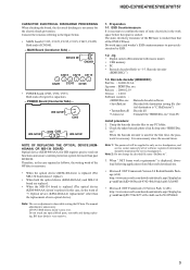
... this set operates normally YES Confirm PS301 to remove the FFC HOLDER (REAR). 2-2. Optical device (KEM-460AAA) replacement") OK Confirm whether DVD (HLX-513)/ NO CD (HLX-A1) can be reproduced Note: Refer to "3. Pass-fail judgment of the optical device (KEM-460AAA) Perform pass-fail judgment to judge whether the repair of [RETURN], [0], [2], [1] [SUBTITLE], and enter the service mode Specification value...
... this set operates normally YES Confirm PS301 to remove the FFC HOLDER (REAR). 2-2. Optical device (KEM-460AAA) replacement") OK Confirm whether DVD (HLX-513)/ NO CD (HLX-A1) can be reproduced Note: Refer to "3. Pass-fail judgment of the optical device (KEM-460AAA) Perform pass-fail judgment to judge whether the repair of [RETURN], [0], [2], [1] [SUBTITLE], and enter the service mode Specification value...
Service Manual
Page 7
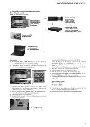
... barcode on the remote commander in flow is an image. Turn the power off . Press the buttons on new optical device (KEM- 460AAA) bottom side by digital camera Change photo into the text data with rear USB connector on , and enter the service mode again. 12. vice (KEM-460AAA) from LOADING ASSY. 2. Completely assemble this set , and complete the repair. Take photo of...
... barcode on the remote commander in flow is an image. Turn the power off . Press the buttons on new optical device (KEM- 460AAA) bottom side by digital camera Change photo into the text data with rear USB connector on , and enter the service mode again. 12. vice (KEM-460AAA) from LOADING ASSY. 2. Completely assemble this set , and complete the repair. Take photo of...
Service Manual
Page 18
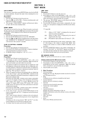
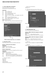
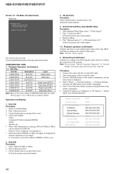
... reset clears data except BD/DVD data stored in an USB memory device. • Diag Performs unit test of devices installed on the board. • Factory Initialize Restores the set to its factory settings. • Network Checks the wired network connection. • Version Up (version update) Not used . • Drive Write drive OP data and check drive. 18 S-AIR ID SETTING CHANGE Procedure: 1. Press the [?/1] button to turn the power...
... reset clears data except BD/DVD data stored in an USB memory device. • Diag Performs unit test of devices installed on the board. • Factory Initialize Restores the set to its factory settings. • Network Checks the wired network connection. • Version Up (version update) Not used . • Drive Write drive OP data and check drive. 18 S-AIR ID SETTING CHANGE Procedure: 1. Press the [?/1] button to turn the power...
Service Manual
Page 20
... Factory Initialize screen [4] Moves to Network screen [5] Moves to Version Up (DISC version update) screen (Not used) [6] Moves to System Information screen [7] Moves to EMC test mode screen (Not used to the screen of service mode. Service Mode Menu [[11]]DDiaiagg [2] Log [3] Factory Initialize [4] Network [5] Version Up [6] System Information [7] EMC Test Mode [8] Drive HELP : [DOWN] [ENT] [(NUM)] HELP (currently available keys, etc.) is first displayed. Screen 1: Selects the test category Operation: [ Diag (Device Test) This screen is accessed from this screen. Each function...
... Factory Initialize screen [4] Moves to Network screen [5] Moves to Version Up (DISC version update) screen (Not used) [6] Moves to System Information screen [7] Moves to EMC test mode screen (Not used to the screen of service mode. Service Mode Menu [[11]]DDiaiagg [2] Log [3] Factory Initialize [4] Network [5] Version Up [6] System Information [7] EMC Test Mode [8] Drive HELP : [DOWN] [ENT] [(NUM)] HELP (currently available keys, etc.) is first displayed. Screen 1: Selects the test category Operation: [ Diag (Device Test) This screen is accessed from this screen. Each function...
Service Manual
Page 21
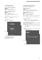
Screen 1: Selects the test category Operation: [ 6. Diag (Audio Input Test) This screen performs audio input test.
Screen 1: Selects the test category Operation: [ 6. Diag (Audio Input Test) This screen performs audio input test.
Service Manual
Page 22
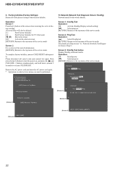
HBD-E370/E470/E570/E870/T57 9. Then press the [?/1] button to turn the power on, and press the [x] and [VOLUME -] buttons simultaneously and hold down (around 5 seconds) to its fac- Screen 1: Ifconfig Test Operation: [3] Activate Ifconfig (Display network setting) [,] Select ping test [RETURN] Returns to the top menu of the service mode To complete factory initialize, process COLD RESET subsequently. Operation: Screen 1 Press the [1] button in other service menus can also be deleted...
HBD-E370/E470/E570/E870/T57 9. Then press the [?/1] button to turn the power on, and press the [x] and [VOLUME -] buttons simultaneously and hold down (around 5 seconds) to its fac- Screen 1: Ifconfig Test Operation: [3] Activate Ifconfig (Display network setting) [,] Select ping test [RETURN] Returns to the top menu of the service mode To complete factory initialize, process COLD RESET subsequently. Operation: Screen 1 Press the [1] button in other service menus can also be deleted...
Service Manual
Page 23
Network (Network Test Diagnosis Screen: Ping) Ping test for the wired ethernet. Screen 1: Ping Test Operation: [ HBD-E370/E470/E570/E870/T57 11.
Network (Network Test Diagnosis Screen: Ping) Ping test for the wired ethernet. Screen 1: Ping Test Operation: [ HBD-E370/E470/E570/E870/T57 11.
Service Manual
Page 26
.../S Video/Component are displayed in each outputs. Note: "AV Sync." Check whether player can play back or not. 4. Select "Setup" → "Network Settings" → "Internet Settings", and press the [3] button on the remote commander, and the home menu is 1080p, the signal of the network. BLX-104 Procedure: 1. Select 1080i (59.94Hz or 50Hz). 2. HLX-513/514 (NTSC), HLX-506/507 (PAL) Procedure: 1. Play "Demonstration 4:3" or "Demonstration 16:9". (Check the picture and sound output) 1-2. Select "View Networks...
.../S Video/Component are displayed in each outputs. Note: "AV Sync." Check whether player can play back or not. 4. Select "Setup" → "Network Settings" → "Internet Settings", and press the [3] button on the remote commander, and the home menu is 1080p, the signal of the network. BLX-104 Procedure: 1. Select 1080i (59.94Hz or 50Hz). 2. HLX-513/514 (NTSC), HLX-506/507 (PAL) Procedure: 1. Play "Demonstration 4:3" or "Demonstration 16:9". (Check the picture and sound output) 1-2. Select "View Networks...
Service Manual
Page 27
... the selected station signal is received in good condition, "TUNED" is 75 ohm. 3. FM TUNER LEVEL CHECK signal generator set . HBD-E370/E470/E570/E870/T57 HBD-E370/E470/E570/E870/T57 27 27 Confirm "TUNED" is lit on the set. 2. Input the following signal from Signal Generator to FM tuner function and tune A, B and C signals. 4. Use signal generator whose output impedance is displayed. Set to FM antenna input directly. You cannot use video cable for A, B and C signals. Turn on the display for checking...
... the selected station signal is received in good condition, "TUNED" is 75 ohm. 3. FM TUNER LEVEL CHECK signal generator set . HBD-E370/E470/E570/E870/T57 HBD-E370/E470/E570/E870/T57 27 27 Confirm "TUNED" is lit on the set. 2. Input the following signal from Signal Generator to FM tuner function and tune A, B and C signals. 4. Use signal generator whose output impedance is displayed. Set to FM antenna input directly. You cannot use video cable for A, B and C signals. Turn on the display for checking...
Service Manual
Page 33
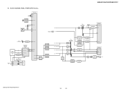
... Xin REMOTE CONTROL RECEIVER IC803 4 SIRCS_IN D506 S700 - 705, 750 3 D508 19 KEY_INT KEY0 - GR10 32 GR11 VEE T800 DC/DC CONVERTER TRANSFORMER DIN 7 CLK 8 STB 9 D803, 804 RECT OSC Q803 5 FL_DOUT 7 FL_CLK 3 FL_CS AC_CUT 20 RESET 12 RESET SWITCH Q504 VOLTAGE DETECTOR IC506 VOLTAGE DETECTOR IC507 RESET SIGNAL GENERATOR IC503 E +14V E +6V E -9V E +4V HBD-E370/E470/E570/E870...
... Xin REMOTE CONTROL RECEIVER IC803 4 SIRCS_IN D506 S700 - 705, 750 3 D508 19 KEY_INT KEY0 - GR10 32 GR11 VEE T800 DC/DC CONVERTER TRANSFORMER DIN 7 CLK 8 STB 9 D803, 804 RECT OSC Q803 5 FL_DOUT 7 FL_CLK 3 FL_CS AC_CUT 20 RESET 12 RESET SWITCH Q504 VOLTAGE DETECTOR IC506 VOLTAGE DETECTOR IC507 RESET SIGNAL GENERATOR IC503 E +14V E +6V E -9V E +4V HBD-E370/E470/E570/E870...
Service Manual
Page 34
... "NOTE OF REPLACING THE IC3100, IC3200 AND IC3400 ON THE MAIN BOARD AND THE COMPLETE MAIN BOARD" on the parts face side seen from (Component Side) the parts face are indicated. • MAIN and MB-134 boards are omitted. • Abbreviation CND : Canadian model • Lead layouts surface Lead layout of conventional IC. F : AUDIO E : VIDEO J : DISC PLAY L : USB d : LAN f : TUNER N : MIC •...
... "NOTE OF REPLACING THE IC3100, IC3200 AND IC3400 ON THE MAIN BOARD AND THE COMPLETE MAIN BOARD" on the parts face side seen from (Component Side) the parts face are indicated. • MAIN and MB-134 boards are omitted. • Abbreviation CND : Canadian model • Lead layouts surface Lead layout of conventional IC. F : AUDIO E : VIDEO J : DISC PLAY L : USB d : LAN f : TUNER N : MIC •...
Service Manual
Page 76
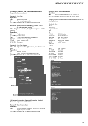
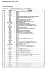
... clock signal input terminal (27 MHz) 76 Not used O Request signal output to the system controller I Chip select signal input from the system controller I Master clock signal input from the digital audio interface receiver O Digital audio data output to the audio section - Not used - Not used O Power on/off control signal output terminal for the front-end serial flash - Not used - Not used - Not used - Not used O Reset signal output to the HDMI ARC OUT connector - HBD-E370/E470/E570/E870/T57 • IC Pin Function Description...
... clock signal input terminal (27 MHz) 76 Not used O Request signal output to the system controller I Chip select signal input from the system controller I Master clock signal input from the digital audio interface receiver O Digital audio data output to the audio section - Not used - Not used O Power on/off control signal output terminal for the front-end serial flash - Not used - Not used - Not used - Not used O Reset signal output to the HDMI ARC OUT connector - HBD-E370/E470/E570/E870/T57 • IC Pin Function Description...
Service Manual
Page 90
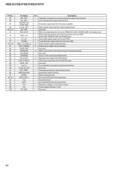
... panel keys - Not used I Power on /off control signal BD decoder O Eject/stop key output to the BD decoder I Reference voltage (+3.3V) input terminal - Not used I Temperature detection signal input terminal I Destination setting terminal I Model setting terminal I Tuned detection signal input from the tuner (FM) O Audio selection signal output terminal O Reset signal output to the serial flash - Not used I AUdio signal output detection signal input terminal - Not used O NSP muting on /off control signal output to stream processor - Noy used 90 HBD...
... panel keys - Not used I Power on /off control signal BD decoder O Eject/stop key output to the BD decoder I Reference voltage (+3.3V) input terminal - Not used I Temperature detection signal input terminal I Destination setting terminal I Model setting terminal I Tuned detection signal input from the tuner (FM) O Audio selection signal output terminal O Reset signal output to the serial flash - Not used I AUdio signal output detection signal input terminal - Not used O NSP muting on /off control signal output to stream processor - Noy used 90 HBD...
Service Manual
Page 91
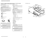
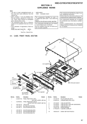
...parts with part number specified. Strictly follow the instructions whenever the components are repaired and/or replaced. Suivre scrupuleusement les instructions chaque fois qu'un composant est remplacé et / ou réparé. 6-1. No. 4 5 Part No. 4-161-647-81 X-2546-720-1 Description ESCUTCHEON (EZ) (E470) LOADING PANEL ASSY (10EZ) Remark 8 4-161-688-01 CASE (EZ) (E570... 91 vice. Replace only with no reference number in the exploded views are not sup- HBD-E370/E470/E570/E870/T57 SECTION 6 EXPLODED VIEWS Note: • -XX and -X mean standardized parts, so they ...
...parts with part number specified. Strictly follow the instructions whenever the components are repaired and/or replaced. Suivre scrupuleusement les instructions chaque fois qu'un composant est remplacé et / ou réparé. 6-1. No. 4 5 Part No. 4-161-647-81 X-2546-720-1 Description ESCUTCHEON (EZ) (E470) LOADING PANEL ASSY (10EZ) Remark 8 4-161-688-01 CASE (EZ) (E570... 91 vice. Replace only with no reference number in the exploded views are not sup- HBD-E370/E470/E570/E870/T57 SECTION 6 EXPLODED VIEWS Note: • -XX and -X mean standardized parts, so they ...
Service Manual
Page 96
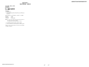
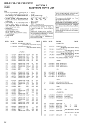
... in the diagrams or the components used on the set. • -XX and -X mean standardized parts, so they are repaired and/or replaced. Part No. METAL OXIDE: Metal oxide-film resistor. Ne les remplacer que par une pièce portant le numéro spécifié. HBD-E370/E470/E570/E870/T57 AUDIO SECTION 7 ELECTRICAL PARTS LIST...
... in the diagrams or the components used on the set. • -XX and -X mean standardized parts, so they are repaired and/or replaced. Part No. METAL OXIDE: Metal oxide-film resistor. Ne les remplacer que par une pièce portant le numéro spécifié. HBD-E370/E470/E570/E870/T57 AUDIO SECTION 7 ELECTRICAL PARTS LIST...


