
Operating Instructions
Page 1
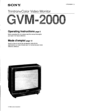
sornt © 1989 by Sony Corporation Mode d'emploi page 12 Avant la mise en service de cet appareil, priere de lire attentivement ce mode d'emploi que Ion conservera pour toute reference ulterieure. SONY® Trinitron®Color Video Monitor 3-750-099-21 (1) Operating Instructions page 2 Before operating the unit, please read this manual thoroughly and retain it for future reference.
sornt © 1989 by Sony Corporation Mode d'emploi page 12 Avant la mise en service de cet appareil, priere de lire attentivement ce mode d'emploi que Ion conservera pour toute reference ulterieure. SONY® Trinitron®Color Video Monitor 3-750-099-21 (1) Operating Instructions page 2 Before operating the unit, please read this manual thoroughly and retain it for future reference.

Operating Instructions
Page 2
... Identify and Resolve Radio-TV Interference Problems". If necessary, the user should consult the dealer or an experienced radio/television technician for a computing device pursuant to provide reasonable protection against such interference in a particular installation. Model No. GVM-2000 Serial No. INFORMATION This equipment generates and uses radio frequency energy and if not installed and used with this equipment does cause...
... Identify and Resolve Radio-TV Interference Problems". If necessary, the user should consult the dealer or an experienced radio/television technician for a computing device pursuant to provide reasonable protection against such interference in a particular installation. Model No. GVM-2000 Serial No. INFORMATION This equipment generates and uses radio frequency energy and if not installed and used with this equipment does cause...
Operating Instructions
Page 3
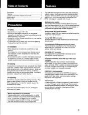
... selected with a wide range of video equipment. Monitoring RGB signals of 15 kHz to 36 kHz horizontal scanning freqencies and 50 Hz to 100 Hz vertical scanning frequencies, and NTSC video signals is output from the wall outlet if it is a high-resolution color video monitor for several days or more. • To disconnect the AC power cord, pull it out by sync polarity. Analog RGB BNC connector Analog RGB signal of video equipment can be...
... selected with a wide range of video equipment. Monitoring RGB signals of 15 kHz to 36 kHz horizontal scanning freqencies and 50 Hz to 100 Hz vertical scanning frequencies, and NTSC video signals is output from the wall outlet if it is a high-resolution color video monitor for several days or more. • To disconnect the AC power cord, pull it out by sync polarity. Analog RGB BNC connector Analog RGB signal of video equipment can be...
Operating Instructions
Page 4
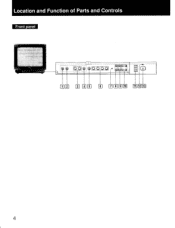
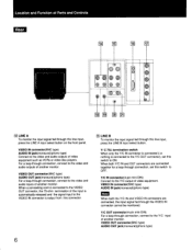
Location and Function of Parts and Controls Front panel ¶ OO 0 0000 as a O 3 r El LEI 111 9 10 Tf 12 13 4
Location and Function of Parts and Controls Front panel ¶ OO 0 0000 as a O 3 r El LEI 111 9 10 Tf 12 13 4
Operating Instructions
Page 5
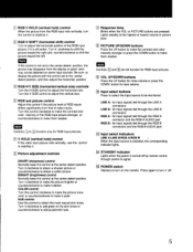
... purple/red hues. to Input select buttons Press to select the input source to adjust the horizontal position of the RGB input picture stronger, or counterclockwise to make them weaker. W RGB H SHIFT (horizontal shift) control Turn to be obtained on the monitor. Turn the V-SIZE control to stabilize it. LINE A: for input signals fed through the LINE A connectors LINE B: for input signals fed through the LINE B connectors RGB A: for input signals fed through control S signal. • RGB V HOLD (vertical hold ) control If the video input picture rolls vertically, use...
... purple/red hues. to Input select buttons Press to select the input source to adjust the horizontal position of the RGB input picture stronger, or counterclockwise to make them weaker. W RGB H SHIFT (horizontal shift) control Turn to be obtained on the monitor. Turn the V-SIZE control to stabilize it. LINE A: for input signals fed through the LINE A connectors LINE B: for input signals fed through the LINE B connectors RGB A: for input signals fed through control S signal. • RGB V HOLD (vertical hold ) control If the video input picture rolls vertically, use...
Operating Instructions
Page 6
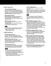
... from this connector. 6 LINE B To monitor the input signal fed through this switch to OFF. When a connecting cord is connected to the VIDEO OUT connector, the 75-ohm termination of the input is automatically released and the signal input to the VIDEO IN connector is connected to the Y/C OUT connector), set this line input, press the LINE B input select button. Y/ C 750 termination switch When only the Y/C IN connector is connected (i.e. VIDEO OUT connector(BNC type) AUDIO OUT...
... from this connector. 6 LINE B To monitor the input signal fed through this switch to OFF. When a connecting cord is connected to the VIDEO OUT connector, the 75-ohm termination of the input is automatically released and the signal input to the VIDEO IN connector is connected to the Y/C OUT connector), set this line input, press the LINE B input select button. Y/ C 750 termination switch When only the Y/C IN connector is connected (i.e. VIDEO OUT connector(BNC type) AUDIO OUT...
Operating Instructions
Page 7
.... Input the horizontal sync signal without serration pulses. *A pulse occurring at the factory, but there may appear on G-signal. The power on/off, * pi TCP volume and picture settings can be remotely controlled through this selector to operate the monitor on the sync signal on the top of video equipment. is connected to the RGB A connector. or 64-color mode is RGB A interface unit 16, 64 COLOR/8 COLOR selector Depress this switch to ON. Keep the...
.... Input the horizontal sync signal without serration pulses. *A pulse occurring at the factory, but there may appear on G-signal. The power on/off, * pi TCP volume and picture settings can be remotely controlled through this selector to operate the monitor on the sync signal on the top of video equipment. is connected to the RGB A connector. or 64-color mode is RGB A interface unit 16, 64 COLOR/8 COLOR selector Depress this switch to ON. Keep the...
Operating Instructions
Page 8
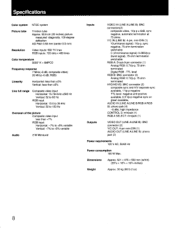
... picture Composite video input less than +7% RGB input Horizontal: -7% to +5% variable Vertical: -7% to +5% variable Audio 2 W Monaural Inputs VIDEO IN (LINE A/LINE B): BNC connectors(2) composite video, 1Vp-p ± 6dB, sync negative, automatic termination at 75 ohms Y/C IN (LINE B): 4-pin, mini-DIN (1) Y(luminance signal): 1Vp-p, sync negative, 75-ohm termination switchable C (chrominance signal): 0.286Vp-p (burst signal), 75-ohm termination switchable RGB A: D-sub 9-pin connector (1) Analog RGB: 0.7Vp-p, 75 ohm terminated Digital RGB : TTL level RGB B: BNC connector (3) Analog RGB...
... picture Composite video input less than +7% RGB input Horizontal: -7% to +5% variable Vertical: -7% to +5% variable Audio 2 W Monaural Inputs VIDEO IN (LINE A/LINE B): BNC connectors(2) composite video, 1Vp-p ± 6dB, sync negative, automatic termination at 75 ohms Y/C IN (LINE B): 4-pin, mini-DIN (1) Y(luminance signal): 1Vp-p, sync negative, 75-ohm termination switchable C (chrominance signal): 0.286Vp-p (burst signal), 75-ohm termination switchable RGB A: D-sub 9-pin connector (1) Analog RGB: 0.7Vp-p, 75 ohm terminated Digital RGB : TTL level RGB B: BNC connector (3) Analog RGB...
Operating Instructions
Page 9
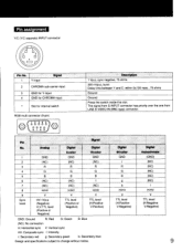
.... 1 2 3 4 5 6 7 8 9 Sync level Analog GND (NC) R G B (NC) (NC) H/HV V HV:1Vp-p (Negative) H,V:TTL level (Positive or Negative) Digital 8-color GND (NC) R G B (NC) (NC) H/HV V TTL level (Positive or Negative) Digital 16-color GND (NC) R G B I (NC) H/HV V TTL level (H:Positive V:Positive) GND: Ground R: Red G: Green B: Blue (NC): No connection H: Horizontal sync V: Vertical sync HV: Composite sync I H/HV V TTL level (H:Negative V:Negative) 9 The signal from S-INPUT connector has priority over the one from LINE B VIDEO IN...
.... 1 2 3 4 5 6 7 8 9 Sync level Analog GND (NC) R G B (NC) (NC) H/HV V HV:1Vp-p (Negative) H,V:TTL level (Positive or Negative) Digital 8-color GND (NC) R G B (NC) (NC) H/HV V TTL level (Positive or Negative) Digital 16-color GND (NC) R G B I (NC) H/HV V TTL level (H:Positive V:Positive) GND: Ground R: Red G: Green B: Blue (NC): No connection H: Horizontal sync V: Vertical sync HV: Composite sync I H/HV V TTL level (H:Negative V:Negative) 9 The signal from S-INPUT connector has priority over the one from LINE B VIDEO IN...

Warranty Card
Page 2
... Gateway Blvd. Ft. CIC 115 Gordon Baker Road Toronto, ON M2H 3R6 or call 1-800-222-7669 any time. For service in the United States: For your convenience, Sony of Canada Ltd. has established a group to supply you with technical support: Sony Technical Support URL: www.sony.com/displays/support EMAIL: [email protected] or write to...
... Gateway Blvd. Ft. CIC 115 Gordon Baker Road Toronto, ON M2H 3R6 or call 1-800-222-7669 any time. For service in the United States: For your convenience, Sony of Canada Ltd. has established a group to supply you with technical support: Sony Technical Support URL: www.sony.com/displays/support EMAIL: [email protected] or write to...


