
Operating Instructions (Flat Panel Display)
Page 7
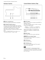
...Function of Parts and Controls 1 Indicator section For details on the Indicator section, see "Indicator Section" on page 8 (GB). 2 Control button section For details on the control button section, see "Connector Panel" on page 9 (GB). 45 6 Side 6 7 (GB) For more details on the power cord, see "...Connecting the AC Power Cord" on page 14 (GB). 6 Connector panel For details on the connector panel, see "Control Button Section (Top)" on page 8 (GB). 3 Stand installation hooks Use these hooks to install the stand (not supplied). 4 SPEAKER ...
...Function of Parts and Controls 1 Indicator section For details on the Indicator section, see "Indicator Section" on page 8 (GB). 2 Control button section For details on the control button section, see "Connector Panel" on page 9 (GB). 45 6 Side 6 7 (GB) For more details on the power cord, see "...Connecting the AC Power Cord" on page 14 (GB). 6 Connector panel For details on the connector panel, see "Control Button Section (Top)" on page 8 (GB). 3 Stand installation hooks Use these hooks to install the stand (not supplied). 4 SPEAKER ...
Operating Instructions (Flat Panel Display)
Page 8
...move the cursor (yellow), set a value, or control speaker volume. 5 ENTER button Press to set your choice. 6 1POWER switch Press to power on page 39 (GB). 1 INPUT button Press to select a signal to be input switches as follows each time you press the INPUT button. Lights up in red... The signal to show menus. Wait about 5 seconds after one of time is input from a computer. INPUT1 INPUT2 OPTION1 OPTION2 (only for the FWD-42LX1) When an option adaptor is not installed in green when the display unit is switched, the indicator blinks green. Lights up in the standby mode...
...move the cursor (yellow), set a value, or control speaker volume. 5 ENTER button Press to set your choice. 6 1POWER switch Press to power on page 39 (GB). 1 INPUT button Press to select a signal to be input switches as follows each time you press the INPUT button. Lights up in red... The signal to show menus. Wait about 5 seconds after one of time is input from a computer. INPUT1 INPUT2 OPTION1 OPTION2 (only for the FWD-42LX1) When an option adaptor is not installed in green when the display unit is switched, the indicator blinks green. Lights up in the standby mode...
Operating Instructions (Flat Panel Display)
Page 10
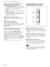
For details on page 42 (GB). Connects to the component signal input or analog RGB signal input... the standby mode, no signal is preinstalled only in the FWD-42LX1.) Y/G PB/CB/B PR/CR/R IN (BNC) : Connects to the connector, see "Pin assignment" on installation, consult your Sony dealers. RGB/COMPONENT ACTIVE THROUGH ADAPTOR BKM-FW12 (Not supplied...VIDEO/COM port) This slot supports video signals and communication function. 9 OPTION2 slot (VIDEO port) (Only for the FWD-42LX1/42LX1E) This slot supports video signals. HD VD IN : Connects to the audio signal output of a piece of ...
For details on page 42 (GB). Connects to the component signal input or analog RGB signal input... the standby mode, no signal is preinstalled only in the FWD-42LX1.) Y/G PB/CB/B PR/CR/R IN (BNC) : Connects to the connector, see "Pin assignment" on installation, consult your Sony dealers. RGB/COMPONENT ACTIVE THROUGH ADAPTOR BKM-FW12 (Not supplied...VIDEO/COM port) This slot supports video signals and communication function. 9 OPTION2 slot (VIDEO port) (Only for the FWD-42LX1/42LX1E) This slot supports video signals. HD VD IN : Connects to the audio signal output of a piece of ...
Operating Instructions (Flat Panel Display)
Page 11
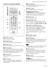
If this displayed information is left undisturbed for a short time, it will disappear automatically. 5 INPUT1 button Press to select the signal input to the INPUT1 connectors. 6 INPUT2 button Press to select the signal input to hide them. Remote Commander RM-980 1 2 MUTING DISPLAY STBY ON 3 4 5 qf 6 qg 7 qh 8 qj 9 ENTER 123 0 456 789 qa 0 qk qs ON SET qd ql MONITOR RM-980 1 POWER ON switch Press to power on the screen. Press again to the INPUT2 connectors. Each press toggles between RGB and COMPONENT. Location and Function of Parts and Controls 7 ...
If this displayed information is left undisturbed for a short time, it will disappear automatically. 5 INPUT1 button Press to select the signal input to the INPUT1 connectors. 6 INPUT2 button Press to select the signal input to hide them. Remote Commander RM-980 1 2 MUTING DISPLAY STBY ON 3 4 5 qf 6 qg 7 qh 8 qj 9 ENTER 123 0 456 789 qa 0 qk qs ON SET qd ql MONITOR RM-980 1 POWER ON switch Press to power on the screen. Press again to the INPUT2 connectors. Each press toggles between RGB and COMPONENT. Location and Function of Parts and Controls 7 ...

Operating Instructions (Flat Panel Display)
Page 12
Press this button and adjust the chroma with the M/m or Location and Function of Parts and Controls qk CHROMA button Adjusts the chroma when the picture mode is set to any of "User1" to "User3."
Press this button and adjust the chroma with the M/m or Location and Function of Parts and Controls qk CHROMA button Adjusts the chroma when the picture mode is set to any of "User1" to "User3."

Operating Instructions (Flat Panel Display)
Page 14
... hum and other noise. • To disconnect the cable, pull it , grasp the plug and pull out the AC power cord. For more details on page 15 (GB).
... hum and other noise. • To disconnect the cable, pull it , grasp the plug and pull out the AC power cord. For more details on page 15 (GB).

Operating Instructions (Flat Panel Display)
Page 16
Using On-screen Menus Using On-screen Menus Operating Through Menus Menu operating buttons Use the buttons on the display. Remote Commander MENU Control button section ENTER Operation of operation using the Remote Commander. Note Operation may differ in some cases since there is explained in these operating instructions for menu operations. The M/m and ENTER buttons on the Remote Commander have the same functions as the M/m and ENTER buttons on the display unit or the Remote Commander for the case of the unit is no
Using On-screen Menus Using On-screen Menus Operating Through Menus Menu operating buttons Use the buttons on the display. Remote Commander MENU Control button section ENTER Operation of operation using the Remote Commander. Note Operation may differ in some cases since there is explained in these operating instructions for menu operations. The M/m and ENTER buttons on the Remote Commander have the same functions as the M/m and ENTER buttons on the display unit or the Remote Commander for the case of the unit is no

Operating Instructions (Flat Panel Display)
Page 17
... Setup You can also adjust the number of the picture. Wide Setup Sets the Auto Wide function. For details, see "Setting Auto Wide" on page 30 (GB). 17 (GB) Aspect Switches the wide screen display to "User3" first. You can make fine adjustment of "User1" to match... the size and type of picture pixels using this menu. For details, see "Resizing and Positioning the Picture" on page 28 (GB). Adjust Screen This menu is used for connecting multiple display units and forming a video wall in a 2 × 2, 3 × 3 or 4 × ...
... Setup You can also adjust the number of the picture. Wide Setup Sets the Auto Wide function. For details, see "Setting Auto Wide" on page 30 (GB). 17 (GB) Aspect Switches the wide screen display to "User3" first. You can make fine adjustment of "User1" to match... the size and type of picture pixels using this menu. For details, see "Resizing and Positioning the Picture" on page 28 (GB). Adjust Screen This menu is used for connecting multiple display units and forming a video wall in a 2 × 2, 3 × 3 or 4 × ...
Operating Instructions (Flat Panel Display)
Page 18
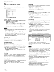
... outputs RGB signals is not set various kinds of the composite synchronous signal, the image may lose the energy saving effects if you turn on page 36 (GB). Notes • "Power Saving: Reduce" will be resumed when you can be carried out for input signals from the speakers ... mode setting 480/60I, 575/50I Composite Video Composite Sync H Sync/V Sync Sync On Green Video signal Synchronizing signal See "Pin assignment" on page 42 (GB) for about five seconds on the screen when you increase Contrast or Brightness. Display Select On to display the input signal information and...
... outputs RGB signals is not set various kinds of the composite synchronous signal, the image may lose the energy saving effects if you turn on page 36 (GB). Notes • "Power Saving: Reduce" will be resumed when you can be carried out for input signals from the speakers ... mode setting 480/60I, 575/50I Composite Video Composite Sync H Sync/V Sync Sync On Green Video signal Synchronizing signal See "Pin assignment" on page 42 (GB) for about five seconds on the screen when you increase Contrast or Brightness. Display Select On to display the input signal information and...
Operating Instructions (Flat Panel Display)
Page 19
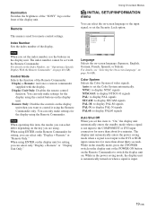
... SETUP/INFORMATION Language: Color System: Auto Shut Off: Security Lock: Information English Auto Off Off Select Set ENTER Exit MENU Language Selects the on page 40 (GB). For details, see "Operating a Specific Display With the Remote Commander" on -screen language (Japanese, English, German, French, Spanish...can only make settings for more than about thirty seconds. Auto: to control it using . Illumination Switches the brightness of the "SONY" logo on the front of video signals. Color System Selects the Color System of the display unit. Remote Only: Disables the controls...
... SETUP/INFORMATION Language: Color System: Auto Shut Off: Security Lock: Information English Auto Off Off Select Set ENTER Exit MENU Language Selects the on page 40 (GB). For details, see "Operating a Specific Display With the Remote Commander" on -screen language (Japanese, English, German, French, Spanish...can only make settings for more than about thirty seconds. Auto: to control it using . Illumination Switches the brightness of the "SONY" logo on the front of video signals. Color System Selects the Color System of the display unit. Remote Only: Disables the controls...
Operating Instructions (Flat Panel Display)
Page 20
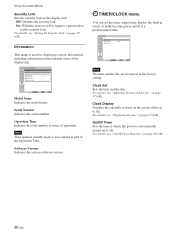
...part of the Operation Time. For details, see "Adjusting the time and the day" on page 37 (GB). Software Version Indicates the system software version. For details, see "Setting the Security Lock" on page 37 (GB). Operation Time Indicates the total number of hours of the display unit. For details..., see "Displaying the time" on page 38 (GB). Information This menu is automatically turned on /off . Clock Set Sets the time and the day. Clock Display Displays the ...
...part of the Operation Time. For details, see "Adjusting the time and the day" on page 37 (GB). Software Version Indicates the system software version. For details, see "Setting the Security Lock" on page 37 (GB). Operation Time Indicates the total number of hours of the display unit. For details..., see "Displaying the time" on page 38 (GB). Information This menu is automatically turned on /off . Clock Set Sets the time and the day. Clock Display Displays the ...
Operating Instructions (Flat Panel Display)
Page 21
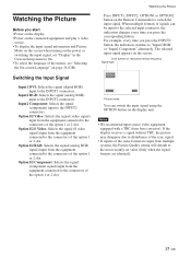
... Input1 DVI: Selects the signal (digital RGB) input to On. • To select the language of the menus, see "Selecting the On-screen Language" on page 36 (GB). Watching the Picture Before you start • Power on the display. • Power on the connected equipment and play a video source. • To...
... Input1 DVI: Selects the signal (digital RGB) input to On. • To select the language of the menus, see "Selecting the On-screen Language" on page 36 (GB). Watching the Picture Before you start • Power on the display. • Power on the connected equipment and play a video source. • To...

Operating Instructions (Flat Panel Display)
Page 40
... Remote Index Number: Control Mode: 1 Display + Remote Select Set ENTER Exit MENU 4 Select the index number with M/m and press ENTER. The main menu appears on page 40 (GB). Monitor index numbers appear in black characters on the lower left menu on the screen. (Every display is allocated an individual preset index...
... Remote Index Number: Control Mode: 1 Display + Remote Select Set ENTER Exit MENU 4 Select the index number with M/m and press ENTER. The main menu appears on page 40 (GB). Monitor index numbers appear in black characters on the lower left menu on the screen. (Every display is allocated an individual preset index...
Operating Instructions (Flat Panel Display)
Page 41
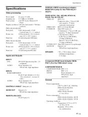
...page 42 (GB).) AUDIO Stereo minijack (×1) 500 mVrms, high impedance CONTROL S IN/OUT Minijack (×2) AUDIO OUT Pinjack (×2) 500 mVrms, high impedance REMOTE (RS-232C) D-sub 9-pin (×1) Specifications VIDEO/S VIDEO input/output adaptor BKM-FW10 (only for the FWD-42LX1... (×1) 500 mVrms, high impedance General Power requirements 100 V to 240 V AC, 50/60 Hz, FWD-42LX1/42LX1E: 2.8 A to 1.1 A FWD-32LX1/32LX1E: 1.7 A to 0.8 A Power consumption FWD-42LX1/42LX1E: 240 W FWD-32LX1/32LX1E: 170 W Operating conditions Temperature: 0 °C to +35 °C (32 °F to...
...page 42 (GB).) AUDIO Stereo minijack (×1) 500 mVrms, high impedance CONTROL S IN/OUT Minijack (×2) AUDIO OUT Pinjack (×2) 500 mVrms, high impedance REMOTE (RS-232C) D-sub 9-pin (×1) Specifications VIDEO/S VIDEO input/output adaptor BKM-FW10 (only for the FWD-42LX1... (×1) 500 mVrms, high impedance General Power requirements 100 V to 240 V AC, 50/60 Hz, FWD-42LX1/42LX1E: 2.8 A to 1.1 A FWD-32LX1/32LX1E: 1.7 A to 0.8 A Power consumption FWD-42LX1/42LX1E: 240 W FWD-32LX1/32LX1E: 170 W Operating conditions Temperature: 0 °C to +35 °C (32 °F to...