
Operating Instructions
Page 2
...injury. You are cautioned that any questions about this equipment. For customers in accordance with Canadian ICES-003. Model No. If you carry the display unit, hold the unit itself, not the speakers. Telephone Number: 858-942-2230 This device complies with the limits for help. Operation is ... interference in the spaces provided below. This equipment has been tested and found to qualified personnel only. Refer servicing to comply with Part 15 of Conformity Trade Name: SONY Model: FWD-40LX1/32LX1R Responsible Party: Sony Electronics Inc. Address: 16450 W.
...injury. You are cautioned that any questions about this equipment. For customers in accordance with Canadian ICES-003. Model No. If you carry the display unit, hold the unit itself, not the speakers. Telephone Number: 858-942-2230 This device complies with the limits for help. Operation is ... interference in the spaces provided below. This equipment has been tested and found to qualified personnel only. Refer servicing to comply with Part 15 of Conformity Trade Name: SONY Model: FWD-40LX1/32LX1R Responsible Party: Sony Electronics Inc. Address: 16450 W.
Operating Instructions
Page 3
Table of Contents Precautions 5 (GB) Location and Function of Parts and Controls ....... 7 (GB) Front / Rear / Side 7 (GB) Indicator Section 8 (GB) Control Button Section (Top 8 (GB) Connector Panel 9 (GB) Remote Commander RM-980 11 (GB) Caution 13 (GB) Connections 14 (GB) Connecting the Speakers 14 (GB) ...(GB) Menu Guide 16 (GB) GB Watching the Picture 21 (GB) Switching the Input Signal 21 (GB) Input Signal, Picture Mode and Display Status Information 22 (GB) Selecting Image Quality 24 (GB) Adjusting the Picture 24 (GB) Adjusting the Contrast, Brightness, Chroma, and Phase, ...
Table of Contents Precautions 5 (GB) Location and Function of Parts and Controls ....... 7 (GB) Front / Rear / Side 7 (GB) Indicator Section 8 (GB) Control Button Section (Top 8 (GB) Connector Panel 9 (GB) Remote Commander RM-980 11 (GB) Caution 13 (GB) Connections 14 (GB) Connecting the Speakers 14 (GB) ...(GB) Menu Guide 16 (GB) GB Watching the Picture 21 (GB) Switching the Input Signal 21 (GB) Input Signal, Picture Mode and Display Status Information 22 (GB) Selecting Image Quality 24 (GB) Adjusting the Picture 24 (GB) Adjusting the Contrast, Brightness, Chroma, and Phase, ...
Operating Instructions
Page 7
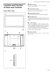
For more details on the power cord, see "Connecting the AC Power Cord" on page 14 (GB). 6 Connector panel For details on the connector panel, see "Control Button Section (Top)" on page 8 (GB). 3 Stand installation hooks Use these hooks to install the stand (not supplied). 4 SPEAKER Socket Connects ... the AC power cord, the POWER/STANDBY indicator lights up in red and the display goes into the standby mode. AC IN socket Connect the supplied AC power cord to this socket to a wall outlet. Location and Function of Parts and Controls Front / Rear / Side Front Rear 2 1 3 Location and Function...
For more details on the power cord, see "Connecting the AC Power Cord" on page 14 (GB). 6 Connector panel For details on the connector panel, see "Control Button Section (Top)" on page 8 (GB). 3 Stand installation hooks Use these hooks to install the stand (not supplied). 4 SPEAKER Socket Connects ... the AC power cord, the POWER/STANDBY indicator lights up in red and the display goes into the standby mode. AC IN socket Connect the supplied AC power cord to this socket to a wall outlet. Location and Function of Parts and Controls Front / Rear / Side Front Rear 2 1 3 Location and Function...
Operating Instructions
Page 8
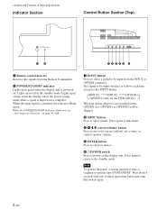
INPUT1 INPUT2 OPTION1 OPTION2 (only for the FWD-40LX1) When an option adaptor is not installed in green when the display unit is required to the standby mode. Press again to return to turn the unit ON/STANDBY. The signal to be skipped. 2 MENU ... signal is switched, the indicator blinks green. Wait about 5 seconds after one of Parts and Controls Indicator Section Control Button Section (Top) 12 12345 6 1 Remote control detector Receives the signals from a computer. Note To protect the panel, a certain amount of time is powered on. Lights up in the standby mode. ...
INPUT1 INPUT2 OPTION1 OPTION2 (only for the FWD-40LX1) When an option adaptor is not installed in green when the display unit is required to the standby mode. Press again to return to turn the unit ON/STANDBY. The signal to be skipped. 2 MENU ... signal is switched, the indicator blinks green. Wait about 5 seconds after one of Parts and Controls Indicator Section Control Button Section (Top) 12 12345 6 1 Remote control detector Receives the signals from a computer. Note To protect the panel, a certain amount of time is powered on. Lights up in the standby mode. ...
Operating Instructions
Page 9
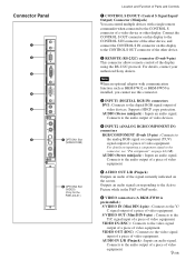
For details, contact your authorized Sony dealers. Supports HDCP copy protection. Connects to the .... S VIDEO OUT (Mini DIN 4-pin) : Connects to the CONTROL S connector of a video device or other display. AUDIO IN L/R (Pinjack) : Inputs an audio signal. Note When an optional adaptor with a single remote commander ...Panel 1 2 3 4 5 DVI-HDCP INPUT 1 AUDIO RGB/COMPONENT INPUT 2 AUDIO L AUDIO OUT R S VIDEO IN OUT VIDEO IN 6 7 OPTION1 Slot (VIDEO/COM ) VIDEO INPUT ADAPTOR OUT AUDIO IN L R 8 OPTION2 Slot (VIDEO) (Only for the FWD-40LX1) Location and Function of Parts...
For details, contact your authorized Sony dealers. Supports HDCP copy protection. Connects to the .... S VIDEO OUT (Mini DIN 4-pin) : Connects to the CONTROL S connector of a video device or other display. AUDIO IN L/R (Pinjack) : Inputs an audio signal. Note When an optional adaptor with a single remote commander ...Panel 1 2 3 4 5 DVI-HDCP INPUT 1 AUDIO RGB/COMPONENT INPUT 2 AUDIO L AUDIO OUT R S VIDEO IN OUT VIDEO IN 6 7 OPTION1 Slot (VIDEO/COM ) VIDEO INPUT ADAPTOR OUT AUDIO IN L R 8 OPTION2 Slot (VIDEO) (Only for the FWD-40LX1) Location and Function of Parts...
Operating Instructions
Page 10
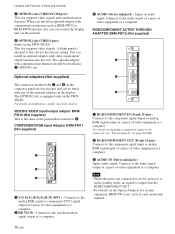
...the RGB/COMPONENT OUT. • For details on the connector panel are slot-in types and can be installed in 7 OPTION1... RGB/COMPONENT ACTIVE THROUGH 10 (GB) You can control the display unit via the network. 8 OPTION2 slot (VIDEO port) (Only.../output adaptor BKMFW10 (Not supplied) This is attached to the synchronization signal output of Parts and Controls 7 OPTION1 slot (VIDEO/COM port) This slot supports video signals and ... connectors marked with 7 and 8 on the Option Adaptors for the FWD-40LX1) This slot supports video signals. When you can install an optional ...Sony dealers.
...the RGB/COMPONENT OUT. • For details on the connector panel are slot-in types and can be installed in 7 OPTION1... RGB/COMPONENT ACTIVE THROUGH 10 (GB) You can control the display unit via the network. 8 OPTION2 slot (VIDEO port) (Only.../output adaptor BKMFW10 (Not supplied) This is attached to the synchronization signal output of Parts and Controls 7 OPTION1 slot (VIDEO/COM port) This slot supports video signals and ... connectors marked with 7 and 8 on the Option Adaptors for the FWD-40LX1) This slot supports video signals. When you can install an optional ...Sony dealers.
Operating Instructions
Page 11
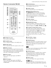
...Standard, and User 1 to 3. 8 ASPECT button Press to change the display to the standby mode. 3 MUTING button Press to display the input signal information and the picture mode on the screen. Location and Function of Parts and Controls 7 PICTURE button Selects Picture mode. Remote Commander RM-980 ...1 2 MUTING DISPLAY STBY ON 3 4 5 qf 6 qg 7 qh 8 qj 9 ENTER 123 0 456 789 qa 0 qk qs ON SET ...
...Standard, and User 1 to 3. 8 ASPECT button Press to change the display to the standby mode. 3 MUTING button Press to display the input signal information and the picture mode on the screen. Location and Function of Parts and Controls 7 PICTURE button Selects Picture mode. Remote Commander RM-980 ...1 2 MUTING DISPLAY STBY ON 3 4 5 qf 6 qg 7 qh 8 qj 9 ENTER 123 0 456 789 qa 0 qk qs ON SET ...
Operating Instructions
Page 12
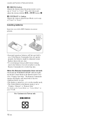
Press this button and adjust the chroma with the M/m or Location and Function of Parts and Controls qk CHROMA button Adjusts the chroma when the picture mode is set to any of "User1" to "User3."
Press this button and adjust the chroma with the M/m or Location and Function of Parts and Controls qk CHROMA button Adjusts the chroma when the picture mode is set to any of "User1" to "User3."
Operating Instructions
Page 15
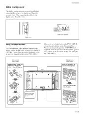
...the hooking nails. 2 Speaker cord holder (Only for the FWD-40LX1) FWD-32LX1R Cable holder Inset the cable holder into the slits. 1 2 15 (GB) Choose three successive blank parts of the air vents for the FWD32LX1R). Choose six out of the display unit. (Only for the FWD40LX1) 3 Insert the cable ...can bundle the cables with the supplied cable holders (×6 for the FWD-40LX1 and ×4 for the cable holder on the unit and rotate it about 90 degrees. 1 Rear FWD-40LX1 Cable holder Press the hinge part to the display, close the cable covers. When you connect the speakers SS-SP40FW ...
...the hooking nails. 2 Speaker cord holder (Only for the FWD-40LX1) FWD-32LX1R Cable holder Inset the cable holder into the slits. 1 2 15 (GB) Choose three successive blank parts of the air vents for the FWD32LX1R). Choose six out of the display unit. (Only for the FWD40LX1) 3 Insert the cable ...can bundle the cables with the supplied cable holders (×6 for the FWD-40LX1 and ×4 for the cable holder on the unit and rotate it about 90 degrees. 1 Rear FWD-40LX1 Cable holder Press the hinge part to the display, close the cable covers. When you connect the speakers SS-SP40FW ...

Operating Instructions
Page 20
...display unit and an optional adaptor with communication function such as BKM-FW32 or BKM-FW50. For details, see "Displaying... On. TIMER/CLOCK Clock Set Clock Display: Off On/Off Timer Select Set ENTER... at which the power is used for displaying various information, including information on page 39...Display Displays the currently set time on the screen when set the timer, adjust time, display ...MENU Note "IP Address" appears on the display unit. All Reset Resets all the adjustments and... status of the display unit. Serial Number Indicates the serial number. Manual...
...display unit and an optional adaptor with communication function such as BKM-FW32 or BKM-FW50. For details, see "Displaying... On. TIMER/CLOCK Clock Set Clock Display: Off On/Off Timer Select Set ENTER... at which the power is used for displaying various information, including information on page 39...Display Displays the currently set time on the screen when set the timer, adjust time, display ...MENU Note "IP Address" appears on the display unit. All Reset Resets all the adjustments and... status of the display unit. Serial Number Indicates the serial number. Manual...


