
Service Manual
Page 2
... WHENEVER CRITICAL COMPONENTS ARE REPLACED OR IMPROPER OPERATION IS SUSPECTED. - 2 - C 4 WARNING 4 2. CIRCUIT ADJUSTMENTS 7 4. AN ISOLATION TRANSFORMER SHOULD BE USED DURING ANY SERVICE TO AVOID POSSIBLE SHOCK HAZARD, BECAUSE OF LIVE CHASSIS. ON THE SCHEMATIC DIAGRAMS, EXPLODED VIEWS AND IN THE PARTS LIST ARE CRITICAL TO SAFE OPERATION. Block Diagram (1 9 4-2. REPLACE THESECOMPONENTS WITH SONY PARTS WHOSE PART NUMBERS APPEAR AS SHOWN IN THIS MANUAL OR IN SUPPLEMENTS PUBLISHED BY SONY. FDL-PT222 SPECIFICATIONS TABLE...
... WHENEVER CRITICAL COMPONENTS ARE REPLACED OR IMPROPER OPERATION IS SUSPECTED. - 2 - C 4 WARNING 4 2. CIRCUIT ADJUSTMENTS 7 4. AN ISOLATION TRANSFORMER SHOULD BE USED DURING ANY SERVICE TO AVOID POSSIBLE SHOCK HAZARD, BECAUSE OF LIVE CHASSIS. ON THE SCHEMATIC DIAGRAMS, EXPLODED VIEWS AND IN THE PARTS LIST ARE CRITICAL TO SAFE OPERATION. Block Diagram (1 9 4-2. REPLACE THESECOMPONENTS WITH SONY PARTS WHOSE PART NUMBERS APPEAR AS SHOWN IN THIS MANUAL OR IN SUPPLEMENTS PUBLISHED BY SONY. FDL-PT222 SPECIFICATIONS TABLE...
Service Manual
Page 3
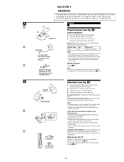
The page numbers of the Operating Instruction Manual remain as in the manual. (Part no : 4-083-376-11) - 3 - SECTION 1 GENERAL The operating instructions mentioned here are partial abstracts from the Operating Instructions Manual.
The page numbers of the Operating Instruction Manual remain as in the manual. (Part no : 4-083-376-11) - 3 - SECTION 1 GENERAL The operating instructions mentioned here are partial abstracts from the Operating Instructions Manual.
Service Manual
Page 5
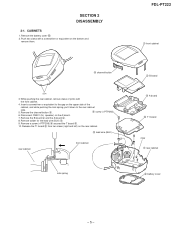
... gap on the bottom and remove them. Remove the channel button 2. 6 screw (+PTP2X6) 6. Push two claws with the front cabinet. 4. FDL-PT222 1 front cabinet 2 channel button claw 3. Insert a screwdriver or equivalent to the rear cabinet side. 5. Remove solder for speaker) on the rear cabinet. 9 lead wire (BLK) rear cabinet front cabinet lock spring 3 B board 4 A board 5 T1 board claw 7 rear cabinet 8 battery cover - 5 - Remove the battery cover 8. 2. Release...
... gap on the bottom and remove them. Remove the channel button 2. 6 screw (+PTP2X6) 6. Push two claws with the front cabinet. 4. FDL-PT222 1 front cabinet 2 channel button claw 3. Insert a screwdriver or equivalent to the rear cabinet side. 5. Remove solder for speaker) on the rear cabinet. 9 lead wire (BLK) rear cabinet front cabinet lock spring 3 B board 4 A board 5 T1 board claw 7 rear cabinet 8 battery cover - 5 - Remove the battery cover 8. 2. Release...

Service Manual
Page 7
... zero at 45.75 MHz is close to obtain the value shown below. Connect a 1 kΩ resistor between JL32 (+4.5V) and JL33 (GND). T1 board - (Component side) RV201 T201 T202 RV002 RV004 RV001 TU101 [ADJUSTMNT] 1. Make sure that waveform is the lowest point. FDL-PT222 SECTION 3 CIRCUIT ADJUSTMENTS 3-1.A BOARD ADJUSTMENT [+4.5V ALIGNMENT (RV601)] Using a digital voltmeter measuring the voltage between...
... zero at 45.75 MHz is close to obtain the value shown below. Connect a 1 kΩ resistor between JL32 (+4.5V) and JL33 (GND). T1 board - (Component side) RV201 T201 T202 RV002 RV004 RV001 TU101 [ADJUSTMNT] 1. Make sure that waveform is the lowest point. FDL-PT222 SECTION 3 CIRCUIT ADJUSTMENTS 3-1.A BOARD ADJUSTMENT [+4.5V ALIGNMENT (RV601)] Using a digital voltmeter measuring the voltage between...

Service Manual
Page 8
... the standards. 6. Receive channel 2 and align the channel display positions with RV001(UP). 8. Remove the potentiometer (47kΩ+15kΩ) you connected between JL84 (AUTO CB) and JL67 (D. Also remove the short you connected be - Set S601 to VHF position and receive a VHF color bar signal issued from the signal generator. 2. Set S601 to shift. 9. Receive channel 14 and align the display position with RV002...
... the standards. 6. Receive channel 2 and align the channel display positions with RV001(UP). 8. Remove the potentiometer (47kΩ+15kΩ) you connected between JL84 (AUTO CB) and JL67 (D. Also remove the short you connected be - Set S601 to VHF position and receive a VHF color bar signal issued from the signal generator. 2. Set S601 to shift. 9. Receive channel 14 and align the display position with RV002...

Service Manual
Page 9
... CH13 UP 18 UA 22 CHANNEL DISPLAY RV002 POSITION CH1 V LOW CHANNEL DISPLAY RV004 POSITION CH12 V HI 20 VLP 19 VHP 23 VHA 24 VLA INITIAL SET CHARGE/ DISCHARGE CIRCUIT BAR DISPLAY POSITION ADJUST HP 3 DEFEAT OUTPUT FILTER SWF201 DEF 14 IF IF RV201 ...OUTPUT V 30 U 31 11 UP DOWN SW T1 (TUNER, VIF/SIF DET) - 9 - - 10 - 4-1. BLOCK DIAGRAM (1) SECTION 4 DIAGRAMS STRAP ANTENNA J101 EXT ANT BALUN T101 ANT IF IF UB TU101 TUNER AGC IF AMP Q201 HB SWITCH LB Q010-012 +4.5V MB IF IC001 TUNER CONTROOL BS 28 BS COMPOSITION U/V 27 BAND SELECT TUNING CONTROL BAND SELECT AUTO...
... CH13 UP 18 UA 22 CHANNEL DISPLAY RV002 POSITION CH1 V LOW CHANNEL DISPLAY RV004 POSITION CH12 V HI 20 VLP 19 VHP 23 VHA 24 VLA INITIAL SET CHARGE/ DISCHARGE CIRCUIT BAR DISPLAY POSITION ADJUST HP 3 DEFEAT OUTPUT FILTER SWF201 DEF 14 IF IF RV201 ...OUTPUT V 30 U 31 11 UP DOWN SW T1 (TUNER, VIF/SIF DET) - 9 - - 10 - 4-1. BLOCK DIAGRAM (1) SECTION 4 DIAGRAMS STRAP ANTENNA J101 EXT ANT BALUN T101 ANT IF IF UB TU101 TUNER AGC IF AMP Q201 HB SWITCH LB Q010-012 +4.5V MB IF IC001 TUNER CONTROOL BS 28 BS COMPOSITION U/V 27 BAND SELECT TUNING CONTROL BAND SELECT AUTO...

Service Manual
Page 10
...CN201 IC501 HEADPHONE AMP 3 AUDIO AUDIO 5 2 RV501 VOL VCC 6 V+ 7 VIDEO VIDEO 9 AUDIO AUDIO CN601 2 3 CN301 VHF 2 H.P 3 J501 2 SPEAKER VIDEO 9 VIDEO 9 BUFFER Q403 VIDEO SYNC. Q302 BRT 11 FR701 LCD BACK LIGHT B (Y/C JUNGLE, MONITOR CONTROL) 35 H IN 38 INB 40 R 23 AUTO CB 28...PORT SWITCH Q601-603 8 RV601 +4.5V 4 6 +4.5V 7 3 BATTERY S001 S002 - 4-2. SEP. CH + BUFFER Q401 +30V 11 RV450 BRT T701 3 DRIVE Q701 2 J701 DC IN 4.5V D701 8 DRIVE Q702 4 1 6 5 A (POWER SUPPLY, LCD BACK LIGHT, HEADPHONE AMP) H SYNC 7 IND 8 IC301 Y/C JUNGLE 1 VIDEO...
...CN201 IC501 HEADPHONE AMP 3 AUDIO AUDIO 5 2 RV501 VOL VCC 6 V+ 7 VIDEO VIDEO 9 AUDIO AUDIO CN601 2 3 CN301 VHF 2 H.P 3 J501 2 SPEAKER VIDEO 9 VIDEO 9 BUFFER Q403 VIDEO SYNC. Q302 BRT 11 FR701 LCD BACK LIGHT B (Y/C JUNGLE, MONITOR CONTROL) 35 H IN 38 INB 40 R 23 AUTO CB 28...PORT SWITCH Q601-603 8 RV601 +4.5V 4 6 +4.5V 7 3 BATTERY S001 S002 - 4-2. SEP. CH + BUFFER Q401 +30V 11 RV450 BRT T701 3 DRIVE Q701 2 J701 DC IN 4.5V D701 8 DRIVE Q702 4 1 6 5 A (POWER SUPPLY, LCD BACK LIGHT, HEADPHONE AMP) H SYNC 7 IND 8 IC301 Y/C JUNGLE 1 VIDEO...
Service Manual
Page 11
... power, is on the Shematic Diagram, see the another list • Readings are taken with a color-bar signal input. • Readings are taken with a 10MΩ digital multimeter. • Voltages are waveform references. • : B+ bus. • : B- MEMO - 13 - 4-3. The components identified by the semiconductors on the component slde. Replace only with fuse of semiconductors in V. • Circled numbers are dc with part number...
... power, is on the Shematic Diagram, see the another list • Readings are taken with a color-bar signal input. • Readings are taken with a 10MΩ digital multimeter. • Voltages are waveform references. • : B+ bus. • : B- MEMO - 13 - 4-3. The components identified by the semiconductors on the component slde. Replace only with fuse of semiconductors in V. • Circled numbers are dc with part number...

Service Manual
Page 14
... NJM2070M NC 1 8 NC +INPUT 2 -INPUT 3 GND 4 BIAS 300Ω + - 50kΩ 100kΩ 7 V+ 6 OUTPUT 5 POWER GND A B C D E F G 1 2 3 4 5 6 7 8 9 2 SP.GND J501 2 SP TO SPEAKER CN501 2P 1 CN602 12P TO T1 BOARD CN201 D.GND 1 VHF 2 H.P 3 4.5V 4 AUDIO 5 30V 6 H.SYNC 7 IND 8 VIDEO 9 A.GND 10 UP DOWN SW 11 UB 12 DRY BATTERY 3PCS. 4.5V A POWER SUPPLY, LCD BACK LIGHT, R513 2.2 :CHIP HEADPHONE AMP C506 0.1 25V F:CHIP...
... NJM2070M NC 1 8 NC +INPUT 2 -INPUT 3 GND 4 BIAS 300Ω + - 50kΩ 100kΩ 7 V+ 6 OUTPUT 5 POWER GND A B C D E F G 1 2 3 4 5 6 7 8 9 2 SP.GND J501 2 SP TO SPEAKER CN501 2P 1 CN602 12P TO T1 BOARD CN201 D.GND 1 VHF 2 H.P 3 4.5V 4 AUDIO 5 30V 6 H.SYNC 7 IND 8 VIDEO 9 A.GND 10 UP DOWN SW 11 UB 12 DRY BATTERY 3PCS. 4.5V A POWER SUPPLY, LCD BACK LIGHT, R513 2.2 :CHIP HEADPHONE AMP C506 0.1 25V F:CHIP...

Service Manual
Page 15
... C-4 2 Q602 D-4 2 Q603 F-4 2 Q610 C-5 2 Q701 G-3 2 Q702 G-3 2 VARIABLE RESISTOR RV450 C-6 RV501 D-5 RV601 C-5 A BOARD IC VOLTAGE LIST Pin Volt IC501 1 - 20 3 0.6 4 GND 5 GND 6 1.3 7 3.4 8- A [AUDIO AMP, PC IN, BACK LIGHT ] - A BOARD DIODE * D406 G-5 6 D601 G-4 3 D602 D-4 5 D603 G-4 4 D604 C-5 3 D605 C-4 3 D701 D-3 - A Board - 1 2 3 4 A B C D < Component Side > E F A BOARD TRANSISTOR VOLTAGE LIST G BCE Q401 13.9 30.5 13.4 Q601 0.5 1.2 GND Q602 0.7 3.1 0.2 Q603 0.2 3.0 GND Q610 30.7 0.5 30...
... C-4 2 Q602 D-4 2 Q603 F-4 2 Q610 C-5 2 Q701 G-3 2 Q702 G-3 2 VARIABLE RESISTOR RV450 C-6 RV501 D-5 RV601 C-5 A BOARD IC VOLTAGE LIST Pin Volt IC501 1 - 20 3 0.6 4 GND 5 GND 6 1.3 7 3.4 8- A [AUDIO AMP, PC IN, BACK LIGHT ] - A BOARD DIODE * D406 G-5 6 D601 G-4 3 D602 D-4 5 D603 G-4 4 D604 C-5 3 D605 C-4 3 D701 D-3 - A Board - 1 2 3 4 A B C D < Component Side > E F A BOARD TRANSISTOR VOLTAGE LIST G BCE Q401 13.9 30.5 13.4 Q601 0.5 1.2 GND Q602 0.7 3.1 0.2 Q603 0.2 3.0 GND Q610 30.7 0.5 30...

Service Manual
Page 18
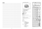
...-104-19 +P 2x6 1 2 The components identified by shading and mark ! R--E-F-.-N--O-. -P-A-R--T-N--O-. -D-E-S-C--R-I-P-T-I -O-N- -R-E-M--A-R--K- NOTE: • Items with part number specified. 3 4 5 6 12 13 9 15 14 17 18 19 16 A 20 19 7 8 21 22 A 23 11 24 25 R--E-F-.-N--O-. -P-A-R--T-N--O-. -D-E-S-C--R-I-P-T-I -O-N- 1 4-561-075-51 CABINET, FRONT 2 4-561-076-01 SWITCH, POWER 3 4-561-093-03 BUTTON, CHANNEL 4 4-561-090-01 SHIELD, PANEL 5 1-803-293-11 MODULE, INDICATOR...
...-104-19 +P 2x6 1 2 The components identified by shading and mark ! R--E-F-.-N--O-. -P-A-R--T-N--O-. -D-E-S-C--R-I-P-T-I -O-N- -R-E-M--A-R--K- NOTE: • Items with part number specified. 3 4 5 6 12 13 9 15 14 17 18 19 16 A 20 19 7 8 21 22 A 23 11 24 25 R--E-F-.-N--O-. -P-A-R--T-N--O-. -D-E-S-C--R-I-P-T-I -O-N- 1 4-561-075-51 CABINET, FRONT 2 4-561-076-01 SWITCH, POWER 3 4-561-093-03 BUTTON, CHANNEL 4 4-561-090-01 SHIELD, PANEL 5 1-803-293-11 MODULE, INDICATOR...

Service Manual
Page 19
...-21 JACK, SMALL TYPE (EXT...service. Therefore, when ordering parts by reference number, please include the board name. When indicating parts by the reference number, please include the board name. RESISTORS • All resistors are in ohms • F : nonflammable • CAPACITORS PF : µµ F • There are seldom required for safety. Replace only with part number specified. The components identified by shading and mark ! FDL-PT222... SECTION 6 ELECTRICAL PARTS LIST...
...-21 JACK, SMALL TYPE (EXT...service. Therefore, when ordering parts by reference number, please include the board name. When indicating parts by the reference number, please include the board name. RESISTORS • All resistors are in ohms • F : nonflammable • CAPACITORS PF : µµ F • There are seldom required for safety. Replace only with part number specified. The components identified by shading and mark ! FDL-PT222... SECTION 6 ELECTRICAL PARTS LIST...
Service Manual
Page 20
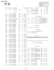
...RES, ADJ, CARBON 47K (CHANNEL DISPLAY POSITION 13ch) 1-223-588-11 RES, ADJ, CARBON 47K (CHANNEL DISPLAY POSITION 1ch) 1-223-589-11 RES, ADJ, CARBON 100K (CHANNEL DISPLAY POSITION 12ch) 1-223-583-11...411-278-11 COIL 1-411-278-11 COIL TU101! 1-693-467-11 TUNER UNIT R201 R202 R205 R206 R208 R209 R210 R212 R213 R214 R215 R216 ... -P-A-R--T-N--O-. -D-E-S-C--R-I-P-T-I -O-N- -R-E-M--A-R--K- R--E-F-.-N--O-. -P-A-R--T-N--O-. -D-E-S-C--R-I-P-T-I -O-N- -R-E-M--A-R--K- FDL-PT222 T1 B The components identified by shading and mark ! are critical for safety. Replace only with part number specified.
...RES, ADJ, CARBON 47K (CHANNEL DISPLAY POSITION 13ch) 1-223-588-11 RES, ADJ, CARBON 47K (CHANNEL DISPLAY POSITION 1ch) 1-223-589-11 RES, ADJ, CARBON 100K (CHANNEL DISPLAY POSITION 12ch) 1-223-583-11...411-278-11 COIL 1-411-278-11 COIL TU101! 1-693-467-11 TUNER UNIT R201 R202 R205 R206 R208 R209 R210 R212 R213 R214 R215 R216 ... -P-A-R--T-N--O-. -D-E-S-C--R-I-P-T-I -O-N- -R-E-M--A-R--K- R--E-F-.-N--O-. -P-A-R--T-N--O-. -D-E-S-C--R-I-P-T-I -O-N- -R-E-M--A-R--K- FDL-PT222 T1 B The components identified by shading and mark ! are critical for safety. Replace only with part number specified.
Service Manual
Page 22
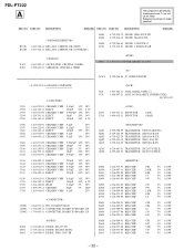
... -P-A-R--T-N--O-. -D-E-S-C--R-I-P-T-I -O-N- FDL-PT222 A The components identified by shading and...-61 DIODE 1SS355TE-17 8-719-210-21 DIODE 11EQS04-TA1B -R-E-M--A-R--K- Replace only with part number specified. X301 X401 1-567-505-11 OSCILLATOR, CRYSTAL 3.58MHz ...1-760-601-21 VIBRATOR, CRYSTAL 4.5MHZ F601 ! 1-533-631-31 FUSE, MICRO 1A 125V IC501 8-759-046-84 IC NJM2070M-TE2 * A-1299-522-A A BOARD, COMPLETE J501 1-563-282-11 JACK, SMALL TYPE (2) J701 1-568-907-21 JACK, DC(POLARITY UNIFIED TYPE...
... -P-A-R--T-N--O-. -D-E-S-C--R-I-P-T-I -O-N- FDL-PT222 A The components identified by shading and...-61 DIODE 1SS355TE-17 8-719-210-21 DIODE 11EQS04-TA1B -R-E-M--A-R--K- Replace only with part number specified. X301 X401 1-567-505-11 OSCILLATOR, CRYSTAL 3.58MHz ...1-760-601-21 VIBRATOR, CRYSTAL 4.5MHZ F601 ! 1-533-631-31 FUSE, MICRO 1A 125V IC501 8-759-046-84 IC NJM2070M-TE2 * A-1299-522-A A BOARD, COMPLETE J501 1-563-282-11 JACK, SMALL TYPE (2) J701 1-568-907-21 JACK, DC(POLARITY UNIFIED TYPE...

Service Manual
Page 23
...-368-11 SWITCH, SLIDE (OFF/VHF/UHF) T601 ! 1-431-580-11 TRANSFORMER, DC-DC CONVERTER T701 1-427-918-11 TRANSFORMER, CONVERTER MISCELLANEOUS 1-504-847-11 SPEAKER (2.8cm) 1-517-702-11 LIGHT, BACK 1-754-205-11 ANTENNA, STRAP 1-803-293-11 MODULE, INDICATOR (NTSC) ACCESSORIES 4-083-376-11 MANUAL, INSTRUCTION FDL-PT222 A - 33 - Replace only with part number specified. The components identified by...
...-368-11 SWITCH, SLIDE (OFF/VHF/UHF) T601 ! 1-431-580-11 TRANSFORMER, DC-DC CONVERTER T701 1-427-918-11 TRANSFORMER, CONVERTER MISCELLANEOUS 1-504-847-11 SPEAKER (2.8cm) 1-517-702-11 LIGHT, BACK 1-754-205-11 ANTENNA, STRAP 1-803-293-11 MODULE, INDICATOR (NTSC) ACCESSORIES 4-083-376-11 MANUAL, INSTRUCTION FDL-PT222 A - 33 - Replace only with part number specified. The components identified by...


