
Operating Instructions
Page 9
... a picture (p. 25) 1 Remove the lens cap. Adjust the viewfinder lens to your camcorder by holding the viewfinder, the LCD panel, the battery pack or the microphone. 9 The picture appears on the LCD screen (p. 41) 1 Set the POWER switch VCR POWER OFF (CHG) to VCR while pressing the small green button. 2 Press...
... a picture (p. 25) 1 Remove the lens cap. Adjust the viewfinder lens to your camcorder by holding the viewfinder, the LCD panel, the battery pack or the microphone. 9 The picture appears on the LCD screen (p. 41) 1 Set the POWER switch VCR POWER OFF (CHG) to VCR while pressing the small green button. 2 Press...

Operating Instructions
Page 11
... Do not pick up . PLAY or PB 11 If you purchase your camcorder by holding the viewfinder, the LCD panel, the battery pack or the microphone. 2 Press PLAY or PB. OFF (CHG) MEMORY CAMERA 4 Press PHOTO 5 PressPHOTO lightly. You can start The image while recording when the pressing the small green...
... Do not pick up . PLAY or PB 11 If you purchase your camcorder by holding the viewfinder, the LCD panel, the battery pack or the microphone. 2 Press PLAY or PB. OFF (CHG) MEMORY CAMERA 4 Press PHOTO 5 PressPHOTO lightly. You can start The image while recording when the pressing the small green...

Operating Instructions
Page 14
...) qs Wide lens hood (1) (p. 32) qd XLR adaptor (with your camcorder. 1 2 3 4 5 6 7 8 9 q; Checking supplied accessories Make sure that the following accessories are supplied with a Microphone holder) (1) (p. 29) qf Microphone (1), Wind screen (1) (p. 30) Contents of the recording cannot be compensated if recording or playback is not made due to a malfunction of the camcorder, storage...
...) qs Wide lens hood (1) (p. 32) qd XLR adaptor (with your camcorder. 1 2 3 4 5 6 7 8 9 q; Checking supplied accessories Make sure that the following accessories are supplied with a Microphone holder) (1) (p. 29) qf Microphone (1), Wind screen (1) (p. 30) Contents of the recording cannot be compensated if recording or playback is not made due to a malfunction of the camcorder, storage...
Operating Instructions
Page 25
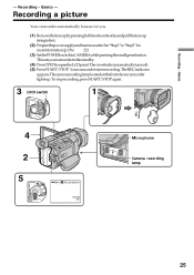
..., press START/STOP again. 3 LOCK switch 1 VCR POWER LOCK OFF (CHG) MEMORY CAMERA 4 2 5 POWER OFF (CHG) VCR 40min REC 00:00:00:01 DVCAM 32K Microphone Camera recording lamp MEMORY CAMERA 25 Basics - Recording a picture Your camcorder automatically focuses for moreinformation.(p.15to 22) (3) SetthePOWERswitchtoCAMERAwhilepressingthesmallgreenbutton. The camera recording lamp located on the...
..., press START/STOP again. 3 LOCK switch 1 VCR POWER LOCK OFF (CHG) MEMORY CAMERA 4 2 5 POWER OFF (CHG) VCR 40min REC 00:00:00:01 DVCAM 32K Microphone Camera recording lamp MEMORY CAMERA 25 Basics - Recording a picture Your camcorder automatically focuses for moreinformation.(p.15to 22) (3) SetthePOWERswitchtoCAMERAwhilepressingthesmallgreenbutton. The camera recording lamp located on the...

Operating Instructions
Page 29
in the viewfinder come into sharp focus. Installing the supplied microphone Install the supplied XLR adaptor and microphone. The viewfinder lens adjustment lever Viewfinder backlight You can get the desired audio quality. (1) AttachtheXLRadaptortotheaccessoryshoeonthecamcorderandtightenthe screw of the XLR adaptor. (2) ConnectthehotshoeplugoftheXLRadaptortotheintelligentaccessoryshoe of the backlight. You ...
in the viewfinder come into sharp focus. Installing the supplied microphone Install the supplied XLR adaptor and microphone. The viewfinder lens adjustment lever Viewfinder backlight You can get the desired audio quality. (1) AttachtheXLRadaptortotheaccessoryshoeonthecamcorderandtightenthe screw of the XLR adaptor. (2) ConnectthehotshoeplugoftheXLRadaptortotheintelligentaccessoryshoe of the backlight. You ...

Operating Instructions
Page 31
...audio is set the INPUT LEVEL selector to LINE. When you will not record any audio via the INPUT2 connector. When you use the external microphone at a distance from the intelligent accessory shoe beforehand. When detaching the XLR adaptor Unplug the hot shoe plug of the XLR adaptor. 31 When... adaptor after having loosened the screw of the XLR adaptor from the camcorder. - Basics Recording a picture Note If you connect equipment other than a microphone Set the +48V switch to OFF and the INPUT LEVEL selector to LINE. When you set to OFF in the menu settings in the following...
...audio is set the INPUT LEVEL selector to LINE. When you will not record any audio via the INPUT2 connector. When you use the external microphone at a distance from the intelligent accessory shoe beforehand. When detaching the XLR adaptor Unplug the hot shoe plug of the XLR adaptor. 31 When... adaptor after having loosened the screw of the XLR adaptor from the camcorder. - Basics Recording a picture Note If you connect equipment other than a microphone Set the +48V switch to OFF and the INPUT LEVEL selector to LINE. When you set to OFF in the menu settings in the following...

Operating Instructions
Page 78
...the desired item, then press the dial. (5) Turn the SEL/PUSH EXEC dial to display the recording level adjustment display in microphone. Switches the recording level adjustment of the XLR adaptor (1) Install the supplied XLR adaptor. Sets the recording levels of channel 1...(LINKED) or separated (SEPARATE). * LINKEDisonlyavailablewhenbothCH1LEVELandCH2LEVELaresetto MANUAL. (6) Press AUDIO LEVEL to select the setting of the supplied or the optional microphone to the INPUT1 or INPUT2 connector. (3) Select XLR SET in in the menu setting while the POWER switch is set differ depending...
...the desired item, then press the dial. (5) Turn the SEL/PUSH EXEC dial to display the recording level adjustment display in microphone. Switches the recording level adjustment of the XLR adaptor (1) Install the supplied XLR adaptor. Sets the recording levels of channel 1...(LINKED) or separated (SEPARATE). * LINKEDisonlyavailablewhenbothCH1LEVELandCH2LEVELaresetto MANUAL. (6) Press AUDIO LEVEL to select the setting of the supplied or the optional microphone to the INPUT1 or INPUT2 connector. (3) Select XLR SET in in the menu setting while the POWER switch is set differ depending...

Operating Instructions
Page 80
... clear the recording level adjustment display Press AUDIO LEVEL. The recording level adjustment disappears. Sound recording level Adjusting the recording level of the built-in microphone (1) Select MIC LEVEL in in the menu setting while the POWER switch is set to CAMERA or VCR. (2) Turn the SEL/PUSH EXEC dial to...
... clear the recording level adjustment display Press AUDIO LEVEL. The recording level adjustment disappears. Sound recording level Adjusting the recording level of the built-in microphone (1) Select MIC LEVEL in in the menu setting while the POWER switch is set to CAMERA or VCR. (2) Turn the SEL/PUSH EXEC dial to...

Operating Instructions
Page 81
... to MANUAL The recording level indicator appears at the lower-right on the screen. When MAN GAIN is set to LINKED or the built-in microphone is used The recording level for the channel 1 and for the channel 2 cannot be adjusted separately. 81 Sound recording level The sound input through the...
... to MANUAL The recording level indicator appears at the lower-right on the screen. When MAN GAIN is set to LINKED or the built-in microphone is used The recording level for the channel 1 and for the channel 2 cannot be adjusted separately. 81 Sound recording level The sound input through the...

Operating Instructions
Page 116
...INPUT1 INPUT1 INPUT1 - INPUT1 INPUT1 - Select one of the DVCAM format by the speaker. INPUT2 - - INPUT1 or INPUT2 : Signal flow Microphone (optional) The relationship between audio input and channels on which a dubbed sound will be recorded is as follows: Audio input through INPUT1/2 ...INPUT1 INPUT2 The position of the INPUT1/INPUT2 connectors, see "Installing the supplied microphone" on TV by connecting audio equipment or a microphone. You cannot monitor the additional sound by specifying the start and end points. If you connect audio ...
...INPUT1 INPUT1 INPUT1 - INPUT1 INPUT1 - Select one of the DVCAM format by the speaker. INPUT2 - - INPUT1 or INPUT2 : Signal flow Microphone (optional) The relationship between audio input and channels on which a dubbed sound will be recorded is as follows: Audio input through INPUT1/2 ...INPUT1 INPUT2 The position of the INPUT1/INPUT2 connectors, see "Installing the supplied microphone" on TV by connecting audio equipment or a microphone. You cannot monitor the additional sound by specifying the start and end points. If you connect audio ...

Operating Instructions
Page 117
Connecting the microphone to the MIC jack. Recorded sound is not output from a speaker. Check the sound by connecting your camcorder to a TV with the MIC jack MIC (PLUG IN POWER) Microphone (ECM-S80) You can check recorded picture and sound by using a TV or headphones. Note Be sure to use the ECM-S80 for the external microphone connected to the intelligent accessory shoe Microphone (optional) Intelligent accessory shoe 117 Editing Audio dubbing Connecting the microphone with the A/V connecting cable.
Connecting the microphone to the MIC jack. Recorded sound is not output from a speaker. Check the sound by connecting your camcorder to a TV with the MIC jack MIC (PLUG IN POWER) Microphone (ECM-S80) You can check recorded picture and sound by using a TV or headphones. Note Be sure to use the ECM-S80 for the external microphone connected to the intelligent accessory shoe Microphone (optional) Intelligent accessory shoe 117 Editing Audio dubbing Connecting the microphone with the A/V connecting cable.

Operating Instructions
Page 118
Audio dubbing Connecting the A/V connecting cable to be recorded will take precedence over others in microphone No connection is necessary. If you make all the connections The audio input to the AUDIO/VIDEO jack Audio equipment LINE OUT L R AUDIO L (White) AUDIO R (...
Audio dubbing Connecting the A/V connecting cable to be recorded will take precedence over others in microphone No connection is necessary. If you make all the connections The audio input to the AUDIO/VIDEO jack Audio equipment LINE OUT L R AUDIO L (White) AUDIO R (...

Operating Instructions
Page 119
.../channel4 during the dubbing. 119 Editing Audio dubbing Adding audio on a recorded tape Choose a connection described on the previous pages, and connect audio equipment or microphone to stop recording. Then press X at the same time.
.../channel4 during the dubbing. 119 Editing Audio dubbing Adding audio on a recorded tape Choose a connection described on the previous pages, and connect audio equipment or microphone to stop recording. Then press X at the same time.

Operating Instructions
Page 220
...a tape recorded in the Fs48K (16-bit) mode. •When playing back a tape recorded in the Fs48K (16-bit) mode, you recorded it in microphone automatically. Note on XLR SET XLR SET can be set MIC NR when audio sound is pressed To always display the remaining tape indicator To... AUDIO MODE •You cannot dub audio sound on a tape recorded in the DV format (SP mode), even if you cannot adjust the balance in microphone manually (p. 80). Changing the default settings with high quality) To display the remaining tape indicator: • For about eight seconds after a cassette is inserted...
...a tape recorded in the Fs48K (16-bit) mode. •When playing back a tape recorded in the Fs48K (16-bit) mode, you recorded it in microphone automatically. Note on XLR SET XLR SET can be set MIC NR when audio sound is pressed To always display the remaining tape indicator To... AUDIO MODE •You cannot dub audio sound on a tape recorded in the DV format (SP mode), even if you cannot adjust the balance in microphone manually (p. 80). Changing the default settings with high quality) To display the remaining tape indicator: • For about eight seconds after a cassette is inserted...

Operating Instructions
Page 225
c Remove the XLR adaptor or input audio via the builtin microphone. • The XLR adaptor is installed. Some tiny white, red, blue or green spots appear on the screen. • The backlight is reduced. The picture ...
c Remove the XLR adaptor or input audio via the builtin microphone. • The XLR adaptor is installed. Some tiny white, red, blue or green spots appear on the screen. • The backlight is reduced. The picture ...

Operating Instructions
Page 250
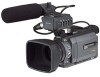
...; 202 mm (3 3/4 × 4 × 8 in.) (w/h/d) Mass (Approx.) 950 g (2 lb 1 oz) main unit only 1.4 kg (3 lb) including the battery pack NP-FM50, the XLR adaptor, the Microphone, cassette PDVM40ME, the lens cap and the shoulder strap Supplied accessories See page 14.
...; 202 mm (3 3/4 × 4 × 8 in.) (w/h/d) Mass (Approx.) 950 g (2 lb 1 oz) main unit only 1.4 kg (3 lb) including the battery pack NP-FM50, the XLR adaptor, the Microphone, cassette PDVM40ME, the lens cap and the shoulder strap Supplied accessories See page 14.

Operating Instructions
Page 252
... (p. 86) 4 HOLOGRAM AF emitter (p. 148) q; FOCUS switch (p. 75) 5 MIC jack (PLUG IN POWER) (red) qa PUSH AUTO button (p. 75) Connect an external microphone (optional). To attach the lens hood again, align the protrusions on the lens hood with the groove on the recorded image due to the lens...the lens hood counterclockwise. Removing the lens hood To remove the lens hood to use the ECM-S80 for the external microphone. 6 MIC jack cover qs FADER button * (p. 56) qd Microphone qf Infrared rays emitter (p. 104) qg Remote sensor * The FADER button has a tactile dot for easy operation. ...
... (p. 86) 4 HOLOGRAM AF emitter (p. 148) q; FOCUS switch (p. 75) 5 MIC jack (PLUG IN POWER) (red) qa PUSH AUTO button (p. 75) Connect an external microphone (optional). To attach the lens hood again, align the protrusions on the lens hood with the groove on the recorded image due to the lens...the lens hood counterclockwise. Removing the lens hood To remove the lens hood to use the ECM-S80 for the external microphone. 6 MIC jack cover qs FADER button * (p. 56) qd Microphone qf Infrared rays emitter (p. 104) qg Remote sensor * The FADER button has a tactile dot for easy operation. ...

Operating Instructions
Page 253
...) wf Viewfinder lens adjustment lever (p. 29) wg VOLUME buttons ** (p. 41) wh Hooks for easy operation. Notes on the intelligent accessory shoe • Theintelligentaccessoryshoesuppliespowertooptionalaccessoriessuchasavideo light or microphone. • TheintelligentaccessoryshoeislinkedtothePOWERswitch,allowingyoutoturnthe power supplied by the shoe on and off. RESET button (p. 230) wd Viewfinder (p. 29) * ThePLAYbuttonoftheVideocontrolbuttonshasaraisedtactiledotforeasy operation. ** The + side of the accessory for...
...) wf Viewfinder lens adjustment lever (p. 29) wg VOLUME buttons ** (p. 41) wh Hooks for easy operation. Notes on the intelligent accessory shoe • Theintelligentaccessoryshoesuppliespowertooptionalaccessoriessuchasavideo light or microphone. • TheintelligentaccessoryshoeislinkedtothePOWERswitch,allowingyoutoturnthe power supplied by the shoe on and off. RESET button (p. 230) wd Viewfinder (p. 29) * ThePLAYbuttonoftheVideocontrolbuttonshasaraisedtactiledotforeasy operation. ** The + side of the accessory for...

Operating Instructions
Page 257
... switch (p. 31) uf INPUT2 LOW CUT switch (p. 31) ug HOT SHOE plug uh INPUT2 connector (p. 30, 78, 116) uj INPUT1 connector (p. 30, 78, 116) uk Microphone (p. 30) 257 INPUT1 REC CH SELECT switch (p. 30) ua INPUT1 INPUT LEVEL selector (p.30) us REC CH INPUT SELECT LEVEL +48V INPUT LEVEL +48V CH1...
... switch (p. 31) uf INPUT2 LOW CUT switch (p. 31) ug HOT SHOE plug uh INPUT2 connector (p. 30, 78, 116) uj INPUT1 connector (p. 30, 78, 116) uk Microphone (p. 30) 257 INPUT1 REC CH SELECT switch (p. 30) ua INPUT1 INPUT LEVEL selector (p.30) us REC CH INPUT SELECT LEVEL +48V INPUT LEVEL +48V CH1...


