Operating Instructions
Page 2
...: (1) This device may be used in a residential installation. Consult the dealer or an experienced radio/ TV technician for a digital device pursuant to persons. This symbol is intended to alert the user to operate this manual could void your authority to the ...relocate the receiving antenna. - Regulatory Information Declaration of the FCC Rules. Operation is subject to comply with Part 15 of Conformity Trade Name: SONY Model No.: DSC-W1 Responsible Party: Sony Electronics Inc. Note: This equipment has been tested and found to the following measures: -
...: (1) This device may be used in a residential installation. Consult the dealer or an experienced radio/ TV technician for a digital device pursuant to persons. This symbol is intended to alert the user to operate this manual could void your authority to the ...relocate the receiving antenna. - Regulatory Information Declaration of the FCC Rules. Operation is subject to comply with Part 15 of Conformity Trade Name: SONY Model No.: DSC-W1 Responsible Party: Sony Electronics Inc. Note: This equipment has been tested and found to the following measures: -
Operating Instructions
Page 3
... with your nearest Sony service station. For more information regarding recycling of the battery used . Notice for your used rechargeable batteries to power this camera. Notice If static... electricity or electromagnetism causes data transfer to this equipment has a detachable fuse cover, be replaced, a fuse of this product. THIS CLASS B DIGITAL APPARATUS COMPLIES...INCLUDING INTERFERENCE THAT MAY CAUSE UNDESIRED OPERATION. and Canada THIS DEVICE COMPLIES WITH PART 15 OF THE FCC RULES. and Canada RECYCLING NICKEL METAL HYDRIDE BATTERIES Nickel Metal ...
... with your nearest Sony service station. For more information regarding recycling of the battery used . Notice for your used rechargeable batteries to power this camera. Notice If static... electricity or electromagnetism causes data transfer to this equipment has a detachable fuse cover, be replaced, a fuse of this product. THIS CLASS B DIGITAL APPARATUS COMPLIES...INCLUDING INTERFERENCE THAT MAY CAUSE UNDESIRED OPERATION. and Canada THIS DEVICE COMPLIES WITH PART 15 OF THE FCC RULES. and Canada RECYCLING NICKEL METAL HYDRIDE BATTERIES Nickel Metal ...
Operating Instructions
Page 6
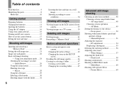
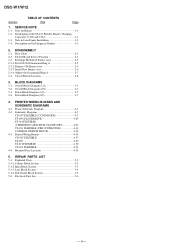
...Shooting according to scene conditions 34 Viewing still images Viewing images on the LCD screen of contents Read this first 4 Identifying the parts 8 Mode dial 10 Getting started Preparing batteries 11 Charging the batteries 11 Inserting the batteries 13 Using the AC adaptor 16 Using your...on a TV screen 39 Deleting still images Deleting images 41 Formatting a "Memory Stick 43 Before advanced operations How to setup and operate your camera 17 How to the subject - Focus preset 50 Shooting with special effects - Flash Level 58 Shooting continuously 59 Shooting in the SET UP ...
...Shooting according to scene conditions 34 Viewing still images Viewing images on the LCD screen of contents Read this first 4 Identifying the parts 8 Mode dial 10 Getting started Preparing batteries 11 Charging the batteries 11 Inserting the batteries 13 Using the AC adaptor 16 Using your...on a TV screen 39 Deleting still images Deleting images 41 Formatting a "Memory Stick 43 Before advanced operations How to setup and operate your camera 17 How to the subject - Focus preset 50 Shooting with special effects - Flash Level 58 Shooting continuously 59 Shooting in the SET UP ...

Operating Instructions
Page 8
You will be unable to firmly secure the camera to tripods having longer screws, and may damage the camera. Identifying the parts See the pages in parentheses for details of operation. 1 2 3 4 5 6 7 8 9 0 qa qs qd qf qg qh qj qk 8 A POWER button (17) B POWER lamp (17) C Shutter button (...
You will be unable to firmly secure the camera to tripods having longer screws, and may damage the camera. Identifying the parts See the pages in parentheses for details of operation. 1 2 3 4 5 6 7 8 9 0 qa qs qd qf qg qh qj qk 8 A POWER button (17) B POWER lamp (17) C Shutter button (...

Operating Instructions
Page 53
...(darker). • Moving objects appear stopped. When setting a slower shutter speed, we recommend using a tripod to the combination of the digital still camera is too small, the image becomes darker. Overexposure • Open the aperture • Set a slower shutter speed Correct exposure Underexposure &#...slower shutter speed when the aperture value is called the "Aperture value (F value)". The proper amount of the lens part which light enters the camera. This value changes according to prevent shaking. The aperture setting value is also important to adjust the exposure in ...
...(darker). • Moving objects appear stopped. When setting a slower shutter speed, we recommend using a tripod to the combination of the digital still camera is too small, the image becomes darker. Overexposure • Open the aperture • Set a slower shutter speed Correct exposure Underexposure &#...slower shutter speed when the aperture value is called the "Aperture value (F value)". The proper amount of the lens part which light enters the camera. This value changes according to prevent shaking. The aperture setting value is also important to adjust the exposure in ...

Operating Instructions
Page 56
...is effective. In such cases, adjusting the exposure in the + (plus) direction is effective. This lets you shoot images that sets which part of the subject. Spot metering ( ) Metering is not overexposed (white out) or underexposed (black out). direction Refer to determine the exposure...Adjust in the - Try various images with different exposures to find the brightness that the image is performed for each region. The camera judges the subject position and background brightness, and determines a well-balanced exposure. Multi-pattern metering (No indicator) The image is ...
...is effective. In such cases, adjusting the exposure in the + (plus) direction is effective. This lets you shoot images that sets which part of the subject. Spot metering ( ) Metering is not overexposed (white out) or underexposed (black out). direction Refer to determine the exposure...Adjust in the - Try various images with different exposures to find the brightness that the image is performed for each region. The camera judges the subject position and background brightness, and determines a well-balanced exposure. Multi-pattern metering (No indicator) The image is ...

Operating Instructions
Page 63
You can enlarge a part of an image up to be enlarged with v/V/b/B. Mode dial MENU Control button Enlarging an image - d Select the desired portion of the image with b/B. Playback ...
You can enlarge a part of an image up to be enlarged with v/V/b/B. Mode dial MENU Control button Enlarging an image - d Select the desired portion of the image with b/B. Playback ...

Operating Instructions
Page 65
...then press z. • You cannot rotate protected images and movies and Multi Burst images. • You may not be displayed at the same time as part of one image. • You cannot cut the Multi Burst image. Mode dial a Set the mode dial to , and display the image to rotate .... Playing back images shot in landscape orientation. Mode dial Control button • When Multi Burst images are played back on a computer or on a camera without the Multi Burst function, the 16 frames you shot will be reflected depending on a computer, the image rotation information may not be able to...
...then press z. • You cannot rotate protected images and movies and Multi Burst images. • You may not be displayed at the same time as part of one image. • You cannot cut the Multi Burst image. Mode dial a Set the mode dial to , and display the image to rotate .... Playing back images shot in landscape orientation. Mode dial Control button • When Multi Burst images are played back on a computer or on a camera without the Multi Burst function, the 16 frames you shot will be reflected depending on a computer, the image rotation information may not be able to...

Operating Instructions
Page 104
... the printer manufacturer. • The printer is not set to be printed. p Disconnect and connect the USB cable again. image. p Consult with the camera. If an error may not be able to [PictBridge] in the index mode depending on the printer. For further information, refer to [PictBridge] (page ...be established. • The printer is not recorded on the p The images that do not have the recording date data cannot be date-inserted part. is printed on . • If you select [Exit] during printing, you cannot print still, disconnect the USB cable, turn off and on ...
... the printer manufacturer. • The printer is not set to be printed. p Disconnect and connect the USB cable again. image. p Consult with the camera. If an error may not be able to [PictBridge] in the index mode depending on the printer. For further information, refer to [PictBridge] (page ...be established. • The printer is not recorded on the p The images that do not have the recording date data cannot be date-inserted part. is printed on . • If you select [Exit] during printing, you cannot print still, disconnect the USB cable, turn off and on ...

Operating Instructions
Page 121
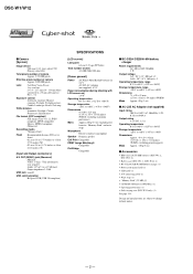
... -20°C to +60°C (-4°F to +140°F) Dimensions Approx. 48 × 29 × 81 mm (1 15/16 × 1 3/16 × 3 1/4 inches) (W/H/D, excluding projecting parts) Mass Approx. 130 g (5 oz) x Accessories • HR6 (size AA) Ni-MH batteries (DSC-W1: 2, DSC-W12: 4) • Battery case (DSC-W1: 1, DSC-W12: 2) • BC...
... -20°C to +60°C (-4°F to +140°F) Dimensions Approx. 48 × 29 × 81 mm (1 15/16 × 1 3/16 × 3 1/4 inches) (W/H/D, excluding projecting parts) Mass Approx. 130 g (5 oz) x Accessories • HR6 (size AA) Ni-MH batteries (DSC-W1: 2, DSC-W12: 4) • Battery case (DSC-W1: 1, DSC-W12: 2) • BC...

Service Manual
Page 1
... are shown. service manual Level 3. The above-described information is available. • Note in The following pages are not shown. DIGITAL STILL CAMERA Electrical parts list Pages 5-7 to 5-8 Therefore, schematic diagram, printed wiring board and electrical and 5-10 to 4-48 the CH-146, SY-...102, SW-422, MS-204, MS-205 flexible, JK-263 Mounted parts location .......... DSC-W1/W12 SERVICE MANUAL Ver 1.2 2004.08 Revision ...
... are shown. service manual Level 3. The above-described information is available. • Note in The following pages are not shown. DIGITAL STILL CAMERA Electrical parts list Pages 5-7 to 5-8 Therefore, schematic diagram, printed wiring board and electrical and 5-10 to 4-48 the CH-146, SY-...102, SW-422, MS-204, MS-205 flexible, JK-263 Mounted parts location .......... DSC-W1/W12 SERVICE MANUAL Ver 1.2 2004.08 Revision ...
Service Manual
Page 2
...Lens Carl Zeiss Vario-Tessar 3 zo om lens f = 7.9 - 23.7 mm (38 - 114 mm when converted to a 35 mm still camera) F2.8 - 5.2 Exposure control Automatic exposure, Manual exposure, Twilight, Twilight portrait, Candle, Landscape, Beach, Soft snap White balance Automatic, Daylight, Cloudy...Design and specifications are subject to +140°F) Dimensions Approx. 48 × 29 × 81mm (1 15/16 × 1 3/16 × 3 1/4 inches) (W/H/D, excluding projecting parts) Mass Approx. 130 g (5 oz) x Accessories • HR6 (size AA) Ni-MH batteries (DSC-W1: 2, DSC-W12: 4) • Battery case (DSC-W1: 1, ...
...Lens Carl Zeiss Vario-Tessar 3 zo om lens f = 7.9 - 23.7 mm (38 - 114 mm when converted to a 35 mm still camera) F2.8 - 5.2 Exposure control Automatic exposure, Manual exposure, Twilight, Twilight portrait, Candle, Landscape, Beach, Soft snap White balance Automatic, Daylight, Cloudy...Design and specifications are subject to +140°F) Dimensions Approx. 48 × 29 × 81mm (1 15/16 × 1 3/16 × 3 1/4 inches) (W/H/D, excluding projecting parts) Mass Approx. 130 g (5 oz) x Accessories • HR6 (size AA) Ni-MH batteries (DSC-W1: 2, DSC-W12: 4) • Battery case (DSC-W1: 1, ...

Service Manual
Page 3
...may also be added to the customer and recommend their replacement. 4. REPLACE THESE COMPONENTS WITH SONY PARTS WHOSE PART NUMBERS APPEAR AS SHOWN IN THIS MANUAL OR IN SUPPLEMENTS PUBLISHED BY SONY. Point them out to ordinary solder. - 3 - Unleaded solder Boards requiring use only unleaded...installed during repairing. • Do not touch the soldering iron on the conductor when soldering or unsoldering. Look for unauthorized replacement parts, particularly transistors, that no wires are printed with the leadfree mark (LF) indicating the solder contains no lead. (Caution: ...
...may also be added to the customer and recommend their replacement. 4. REPLACE THESE COMPONENTS WITH SONY PARTS WHOSE PART NUMBERS APPEAR AS SHOWN IN THIS MANUAL OR IN SUPPLEMENTS PUBLISHED BY SONY. Point them out to ordinary solder. - 3 - Unleaded solder Boards requiring use only unleaded...installed during repairing. • Do not touch the soldering iron on the conductor when soldering or unsoldering. Look for unauthorized replacement parts, particularly transistors, that no wires are printed with the leadfree mark (LF) indicating the solder contains no lead. (Caution: ...
Service Manual
Page 4
...101 FLEXIBLE (CHARGING CAPACITOR, FLASH UNIT 4-29 US-011 FLEXIBLE (USB CONNECTOR 4-31 CONTROL SWITCH BLOCK 4-32 4-3. REPAIR PARTS LIST 5-1. Main Block Section 5-3 5-1-3. Discharging of Barrier Assy 2-5 2-3-1. Remove Old Barrier Assy 2-6 2-3-3. Power Block ...(2/2 3-7 4. Note for Repair 1-1 1-2. SY-102 Board Service Position 2-3 2-3. BLOCK DIAGRAMS 3-1. Frame Schematic Diagram 4-1 4-2. Mounted Parts Location 4-53 5. SERVICE NOTE 1-1. Description on Self-diagnosis Display 1-2 2. Adhere the Ornamental Ring A 2-7 2-4. Circuit Boards Location 2-8...
...101 FLEXIBLE (CHARGING CAPACITOR, FLASH UNIT 4-29 US-011 FLEXIBLE (USB CONNECTOR 4-31 CONTROL SWITCH BLOCK 4-32 4-3. REPAIR PARTS LIST 5-1. Main Block Section 5-3 5-1-3. Discharging of Barrier Assy 2-5 2-3-1. Remove Old Barrier Assy 2-6 2-3-3. Power Block ...(2/2 3-7 4. Note for Repair 1-1 1-2. SY-102 Board Service Position 2-3 2-3. BLOCK DIAGRAMS 3-1. Frame Schematic Diagram 4-1 4-2. Mounted Parts Location 4-53 5. SERVICE NOTE 1-1. Description on Self-diagnosis Display 1-2 2. Adhere the Ornamental Ring A 2-7 2-4. Circuit Boards Location 2-8...

Service Manual
Page 5
... gilt which is kept without discharging when the main power of the unit is snapped. 1-2. Capacitor ST kemikon sheet ST-101 R:1 kΩ/1 W (Part code: 1-215-869-11) Wrap insulating tape. 1-1 The electric shock is caused by hand. Wrap insulating tape fully around the leads of the resistor to ...
... gilt which is kept without discharging when the main power of the unit is snapped. 1-2. Capacitor ST kemikon sheet ST-101 R:1 kΩ/1 W (Part code: 1-215-869-11) Wrap insulating tape. 1-1 The electric shock is caused by hand. Wrap insulating tape fully around the leads of the resistor to ...

Service Manual
Page 7
... the short jig about 10 seconds. FLOW CHART The following flow chart shows the disassembly procedure. SECTION 2 DISASSEMBLY 2-1. Capacitor ST kemikon sheet 2 1 3 2 7 6 5 7 1 ST-101 R:1 kΩ/1 W (Part code: 1-215-869-11) 2 1 4 9 qa 8 0 4 2 5 3 1 Open two connectors (CN201, 701) 1 Lock ace screw (M1.7) x4 0 6 Claw x2 2 Claw x2 2 Claw 7 Strobo block 3 Lens block 3 Rear...
... the short jig about 10 seconds. FLOW CHART The following flow chart shows the disassembly procedure. SECTION 2 DISASSEMBLY 2-1. Capacitor ST kemikon sheet 2 1 3 2 7 6 5 7 1 ST-101 R:1 kΩ/1 W (Part code: 1-215-869-11) 2 1 4 9 qa 8 0 4 2 5 3 1 Open two connectors (CN201, 701) 1 Lock ace screw (M1.7) x4 0 6 Claw x2 2 Claw x2 2 Claw 7 Strobo block 3 Lens block 3 Rear...

Service Manual
Page 9
...-1 frame and prize the ring. * Take extreme care so as not to weaken the adhesive force. EXCHANGE METHOD OF BARRIER ASSY Service parts Part Number 1 3-091-427-01 2 X-3954-476-1 3 3-086-156-31 Part Name Ring (A), Ornamental Barrier Assy Tapping screw (P2) Quantity 1 1 2 Tools used Torque driver Soldering iron Weight about 300ºC.
...-1 frame and prize the ring. * Take extreme care so as not to weaken the adhesive force. EXCHANGE METHOD OF BARRIER ASSY Service parts Part Number 1 3-091-427-01 2 X-3954-476-1 3 3-086-156-31 Part Name Ring (A), Ornamental Barrier Assy Tapping screw (P2) Quantity 1 1 2 Tools used Torque driver Soldering iron Weight about 300ºC.

Service Manual
Page 10
This is an important part to prevent the dust and light from coming in. * After removing the Barrier Assy, take extreme care not to the position shown in the lens ...
This is an important part to prevent the dust and light from coming in. * After removing the Barrier Assy, take extreme care not to the position shown in the lens ...

Service Manual
Page 11
DSC-W1/W12 2-3-4. Note: Be careful not to four recesses on a black mold part. If the weight is put the weight on the top surface of the Barrier Assy. * Do not apply too much adhesive. (Make quantity of adhesives ... quantity in full circumference between Ornamental Ring A and group-1 frame. Adhesive Not gap in the Ornamental Ring A only. Put the 60g weight on the mold part of the spring for preventing static electricity must be present in which a groove hides.) Meeting a "notch" of the Ornamental Ring A with a "projection" of the group...
DSC-W1/W12 2-3-4. Note: Be careful not to four recesses on a black mold part. If the weight is put the weight on the top surface of the Barrier Assy. * Do not apply too much adhesive. (Make quantity of adhesives ... quantity in full circumference between Ornamental Ring A and group-1 frame. Adhesive Not gap in the Ornamental Ring A only. Put the 60g weight on the mold part of the spring for preventing static electricity must be present in which a groove hides.) Meeting a "notch" of the Ornamental Ring A with a "projection" of the group...

Service Manual
Page 21
...The components identified by reference number, please include the board name. Replace only with mark 0 are measured between the measurement points and ground when camera shoots color bar chart of chip. 4-2. pF : µ µF. 50 V or less are not indicated except for safety. kΩ...;=1000 Ω, MΩ=1000 kΩ. • Caution when replacing chip parts. New parts must be indicated as follows. Adjust the distance so that they are reference values and reference waveforms. (VOM of DC 10 MΩ ...
...The components identified by reference number, please include the board name. Replace only with mark 0 are measured between the measurement points and ground when camera shoots color bar chart of chip. 4-2. pF : µ µF. 50 V or less are not indicated except for safety. kΩ...;=1000 Ω, MΩ=1000 kΩ. • Caution when replacing chip parts. New parts must be indicated as follows. Adjust the distance so that they are reference values and reference waveforms. (VOM of DC 10 MΩ ...


