Operating Instructions
Page 1
...Model No. Refer to these numbers whenever you call upon your computer_________ Troubleshooting Additional information Index Digital Still Camera Operating Instructions Before operating the unit, please read this product. DSC-W1/W12 © 2004 Sony Corporation 3-091-535-11(1) Getting started Shooting still images Viewing still images Deleting still images Before...PictBridge printer) Enjoying movies Enjoying images on the bottom. Owner's Record The model and serial numbers are located on your Sony dealer regarding this manual thoroughly, and retain it for future reference.
...Model No. Refer to these numbers whenever you call upon your computer_________ Troubleshooting Additional information Index Digital Still Camera Operating Instructions Before operating the unit, please read this product. DSC-W1/W12 © 2004 Sony Corporation 3-091-535-11(1) Getting started Shooting still images Viewing still images Deleting still images Before...PictBridge printer) Enjoying movies Enjoying images on the bottom. Owner's Record The model and serial numbers are located on your Sony dealer regarding this manual thoroughly, and retain it for future reference.

Operating Instructions
Page 121
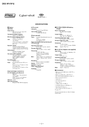
... mm (1 15/16 × 1 3/16 × 3 1/4 inches) (W/H/D, excluding projecting parts) Mass Approx. 130 g (5 oz) x Accessories • HR6 (size AA) Ni-MH batteries (DSC-W1: 2, DSC-W12: 4) • Battery case (DSC-W1: 1, DSC-W12: 2) • BC-CS2A/CS2B Ni-MH Battery charger (1) • Power cord (mains lead) (1) • USB cable (1) • A/V connecting cable (1) • Wrist strap (1) •...
... mm (1 15/16 × 1 3/16 × 3 1/4 inches) (W/H/D, excluding projecting parts) Mass Approx. 130 g (5 oz) x Accessories • HR6 (size AA) Ni-MH batteries (DSC-W1: 2, DSC-W12: 4) • Battery case (DSC-W1: 1, DSC-W12: 2) • BC-CS2A/CS2B Ni-MH Battery charger (1) • Power cord (mains lead) (1) • USB cable (1) • A/V connecting cable (1) • Wrist strap (1) •...

Service Manual
Page 1
...flexible, JK-263 and SP-045 flexible boards are not shown. DSC-W1/W12 SERVICE MANUAL Ver 1.2 2004.08 Revision History How to use Acrobat Reader 2 LEVEL DSC-W1 US Model Canadian Model Hong Kong Model Australian Model Argentine Model... Brazilian Model Tourist Model Japanese Model DSC-W1/W12 AEP Model UK Model E Model Chinese Model Korea Model SPECIFICATIONS SERVICE NOTE DISASSEMBLY ... SW-422, MS-204, MS-205 flexible, JK-263 Mounted parts location .......... DIGITAL STILL CAMERA Pages 4-54 and 4-55 and SP-045 flexible boards.
...flexible, JK-263 and SP-045 flexible boards are not shown. DSC-W1/W12 SERVICE MANUAL Ver 1.2 2004.08 Revision History How to use Acrobat Reader 2 LEVEL DSC-W1 US Model Canadian Model Hong Kong Model Australian Model Argentine Model... Brazilian Model Tourist Model Japanese Model DSC-W1/W12 AEP Model UK Model E Model Chinese Model Korea Model SPECIFICATIONS SERVICE NOTE DISASSEMBLY ... SW-422, MS-204, MS-205 flexible, JK-263 Mounted parts location .......... DIGITAL STILL CAMERA Pages 4-54 and 4-55 and SP-045 flexible boards.
Service Manual
Page 2
... (USB driver SPVD-012) (1) • Operating instructions (1) • Soft carrying case (DSC-W12 only) (1) See page 5-15. DSC-W1/W12 x Camera [System] Image device 9.04 mm (1/1.8 type) color CCD Primary color filter Total pixels number of camera Approx. 5 255 000 pixels Effective pixels number of camera Approx. 5 090 000 pixels Lens Carl Zeiss Vario-Tessar 3 zo om...
... (USB driver SPVD-012) (1) • Operating instructions (1) • Soft carrying case (DSC-W12 only) (1) See page 5-15. DSC-W1/W12 x Camera [System] Image device 9.04 mm (1/1.8 type) color CCD Primary color filter Total pixels number of camera Approx. 5 255 000 pixels Effective pixels number of camera Approx. 5 090 000 pixels Lens Carl Zeiss Vario-Tessar 3 zo om...

Service Manual
Page 3
DSC-W1/W12 SAFETY-RELATED COMPONENT WARNING!! LES COMPOSANTS IDENTIFÉS PAR UNE MARQUE 0 SUR LES ... them out to flow) than ordinary solder. NE REMPLACER CES COMPOSANTS QUE PAR DES PIÈSES SONY DONT LES NUMÉROS SONT DONNÉS DANS CE MANUEL OU DANS LES SUPPÉMENTS PUBLIÉS PAR...solder are "pinched" or contact high-wattage resistors. 3. REPLACE THESE COMPONENTS WITH SONY PARTS WHOSE PART NUMBERS APPEAR AS SHOWN IN THIS MANUAL OR IN SUPPLEMENTS PUBLISHED BY SONY. Look for unauthorized replacement parts, particularly transistors, that no wires are printed ...
DSC-W1/W12 SAFETY-RELATED COMPONENT WARNING!! LES COMPOSANTS IDENTIFÉS PAR UNE MARQUE 0 SUR LES ... them out to flow) than ordinary solder. NE REMPLACER CES COMPOSANTS QUE PAR DES PIÈSES SONY DONT LES NUMÉROS SONT DONNÉS DANS CE MANUEL OU DANS LES SUPPÉMENTS PUBLIÉS PAR...solder are "pinched" or contact high-wattage resistors. 3. REPLACE THESE COMPONENTS WITH SONY PARTS WHOSE PART NUMBERS APPEAR AS SHOWN IN THIS MANUAL OR IN SUPPLEMENTS PUBLISHED BY SONY. Look for unauthorized replacement parts, particularly transistors, that no wires are printed ...
Service Manual
Page 4
Discharging of Barrier Assy 2-5 2-3-1. Flow Chart 2-1 2-2. Overall Block Diagram (1/2 3-1 3-2. PRINTED WIRING BOARDS AND SCHEMATIC DIAGRAMS 4-1. Lens Block Section 5-4 5-1-4. DSC-W1/W12 Section TABLE OF CONTENTS Title Page 1. SERVICE NOTE 1-1. Description on Self-diagnosis Display 1-2 2. Install New Barrier Assy 2-6 2-3-4. Schematic Diagrams 4-5 CD-507 FLEXIBLE (CCD IMAGER 4-7 ST-...
Discharging of Barrier Assy 2-5 2-3-1. Flow Chart 2-1 2-2. Overall Block Diagram (1/2 3-1 3-2. PRINTED WIRING BOARDS AND SCHEMATIC DIAGRAMS 4-1. Lens Block Section 5-4 5-1-4. DSC-W1/W12 Section TABLE OF CONTENTS Title Page 1. SERVICE NOTE 1-1. Description on Self-diagnosis Display 1-2 2. Install New Barrier Assy 2-6 2-3-4. Schematic Diagrams 4-5 CD-507 FLEXIBLE (CCD IMAGER 4-7 ST-...

Service Manual
Page 5
... terminal. The electric shock is snapped. Capacitor ST kemikon sheet ST-101 R:1 kΩ/1 W (Part code: 1-215-869-11) Wrap insulating tape. 1-1 SECTION 1 SERVICE NOTE DSC-W1/W12 1-1. Wrap insulating tape fully around the leads of the resistor to each end of a resistor of connector. When remove a connector, don't pull at wire of...
... terminal. The electric shock is snapped. Capacitor ST kemikon sheet ST-101 R:1 kΩ/1 W (Part code: 1-215-869-11) Wrap insulating tape. 1-1 SECTION 1 SERVICE NOTE DSC-W1/W12 1-1. Wrap insulating tape fully around the leads of the resistor to each end of a resistor of connector. When remove a connector, don't pull at wire of...

Service Manual
Page 6
DSC-W1/W12 1-3. DESCRIPTION ON SELF-DIAGNOSIS DISPLAY Self-diagnosis display • C: ss: ss You can reverse the camera malfunction yourself. (However, contact your Sony dealer or local authorized Sony service facility when you cannot recover from the camera malfunction.) • E: ss: ss Contact your Sony dealer or local authorized Sony service facility. Cause Trouble with hardware. E:91:ss...
DSC-W1/W12 1-3. DESCRIPTION ON SELF-DIAGNOSIS DISPLAY Self-diagnosis display • C: ss: ss You can reverse the camera malfunction yourself. (However, contact your Sony dealer or local authorized Sony service facility when you cannot recover from the camera malfunction.) • E: ss: ss Contact your Sony dealer or local authorized Sony service facility. Cause Trouble with hardware. E:91:ss...

Service Manual
Page 7
... 2 SW-422 8 Claw x2 3 US-011 flexible: CN101 9 LCD block 4 Lock ace screw 0 LCD flexible: CN801 (M1.7) x1 qa Back light 5 Claw x4 flexible: CN802 2-1 2-2 DSC-W1/W12 HELP 1 8 1 3 4 6 5 Note: High-voltage cautions Discharging the Capacitor Short-circuit between the two points with the short jig about 10 seconds. SECTION 2 DISASSEMBLY 2-1.
... 2 SW-422 8 Claw x2 3 US-011 flexible: CN101 9 LCD block 4 Lock ace screw 0 LCD flexible: CN801 (M1.7) x1 qa Back light 5 Claw x4 flexible: CN802 2-1 2-2 DSC-W1/W12 HELP 1 8 1 3 4 6 5 Note: High-voltage cautions Discharging the Capacitor Short-circuit between the two points with the short jig about 10 seconds. SECTION 2 DISASSEMBLY 2-1.

Service Manual
Page 9
... of Ornamental Ring A is about 60g Adhesive (Super X) (Note) Note: Use adhesive (Super X) or an equivalent article. Heat four circled portions with the soldering iron. DSC-W1/W12 1 2 3 2-3-1. Beware of a burn since the entire Ornamental Ring becomes hot. * As the adhesive force of the group-1 frame and prize the ring. * Take extreme...
... of Ornamental Ring A is about 60g Adhesive (Super X) (Note) Note: Use adhesive (Super X) or an equivalent article. Heat four circled portions with the soldering iron. DSC-W1/W12 1 2 3 2-3-1. Beware of a burn since the entire Ornamental Ring becomes hot. * As the adhesive force of the group-1 frame and prize the ring. * Take extreme...

Service Manual
Page 10
... figure. 2 Tighten two screws. * Tightening torque = 0.5 kgf Projection 1 2 2 2-6 This is an important part to prevent the dust and light from coming in the lens barrel. 2-3-3. DSC-W1/W12 2-3-2. REMOVE OLD BARRIER ASSY 1 Remove two screws. * Discard the removed screws. 2 Remove the Barrier Assy. * Discard the removed Barrier Assy. 2 1 1 * After removing the Barrier...
... figure. 2 Tighten two screws. * Tightening torque = 0.5 kgf Projection 1 2 2 2-6 This is an important part to prevent the dust and light from coming in the lens barrel. 2-3-3. DSC-W1/W12 2-3-2. REMOVE OLD BARRIER ASSY 1 Remove two screws. * Discard the removed screws. 2 Remove the Barrier Assy. * Discard the removed Barrier Assy. 2 1 1 * After removing the Barrier...

Service Manual
Page 11
..., if present, causes the crackle sound NG. * The weight must be tilted. Adhesive Not gap in full circumference between Ornamental Ring A and group-1 frame. DSC-W1/W12 2-3-4. Note: Be careful not to four recesses on the mold part of the group-1 frame, push the Ornamental Ring A into the quantity in the Ornamental...
..., if present, causes the crackle sound NG. * The weight must be tilted. Adhesive Not gap in full circumference between Ornamental Ring A and group-1 frame. DSC-W1/W12 2-3-4. Note: Be careful not to four recesses on the mold part of the group-1 frame, push the Ornamental Ring A into the quantity in the Ornamental...

Service Manual
Page 12
DSC-W1/W12 2-4. CIRCUIT BOARDS LOCATION US-011 flexible SY-102 (including CH-146) SW-422 ST-100 CH-146 (included in SY-102) ST-101 flexible MS-... LCD DRIVE, MS CONNECTOR MS-205 flexible CONNECTOR SP-045 flexible SPEAKER ST-100 FLASH DRIVE ST-101 flexible CHARGING CAPACITOR, FLASH UNIT SY-102 CAMERA MODULE, CAMERA DSP, LENS DRIVE, (Including CH-146) SH DSP, FRONT CONTROL, DC/DC CONVERTER SW-422 AUDIO, CONTROL SWITCH US-011 flexible USB CONNECTOR 2-8E...
DSC-W1/W12 2-4. CIRCUIT BOARDS LOCATION US-011 flexible SY-102 (including CH-146) SW-422 ST-100 CH-146 (included in SY-102) ST-101 flexible MS-... LCD DRIVE, MS CONNECTOR MS-205 flexible CONNECTOR SP-045 flexible SPEAKER ST-100 FLASH DRIVE ST-101 flexible CHARGING CAPACITOR, FLASH UNIT SY-102 CAMERA MODULE, CAMERA DSP, LENS DRIVE, (Including CH-146) SH DSP, FRONT CONTROL, DC/DC CONVERTER SW-422 AUDIO, CONTROL SWITCH US-011 flexible USB CONNECTOR 2-8E...

Service Manual
Page 13
Mic harness Front side Sheet (S) US-011 flexible board HELP DSC-W1/W12 HELP Sheet attachment positions and procedures of processing the flexible boards/harnesses are shown.
Mic harness Front side Sheet (S) US-011 flexible board HELP DSC-W1/W12 HELP Sheet attachment positions and procedures of processing the flexible boards/harnesses are shown.

Service Manual
Page 15
..., XCAM RST Y11 AB11 Y10 AA11 AB10 Y9 F1 AB9 AA10 AA9 D1 Y8 AB8 AA8 E1 AB7 AA7 Y7 C6 AB6 D7 AC8 IC301 CAMERA DSP, SDRAM (KWF BOARD) (2/6) G1 AC22 AC12 AC15 N3 K3 M4 K4 J3 T4 P4 U2 T3 D8 T2 AA12 U3 J23 AA19 J22 U20... 7 19 11 21 19 132 124 3 123 126-129 84 Q105 36 135 27 VSUB CONT 20 Q701 CP101 CAMERA MODULE (1/6) 22 ı 35 45 46 48 CA AD00 - D15 MC A1 - DSC-W1/W12 SECTION 3 3. A25 MC CKIO CAM F XFE CS XTG CS LENS TEMP VER EXT CLK XZM DC BR MSHUT...
..., XCAM RST Y11 AB11 Y10 AA11 AB10 Y9 F1 AB9 AA10 AA9 D1 Y8 AB8 AA8 E1 AB7 AA7 Y7 C6 AB6 D7 AC8 IC301 CAMERA DSP, SDRAM (KWF BOARD) (2/6) G1 AC22 AC12 AC15 N3 K3 M4 K4 J3 T4 P4 U2 T3 D8 T2 AA12 U3 J23 AA19 J22 U20... 7 19 11 21 19 132 124 3 123 126-129 84 Q105 36 135 27 VSUB CONT 20 Q701 CP101 CAMERA MODULE (1/6) 22 ı 35 45 46 48 CA AD00 - D15 MC A1 - DSC-W1/W12 SECTION 3 3. A25 MC CKIO CAM F XFE CS XTG CS LENS TEMP VER EXT CLK XZM DC BR MSHUT...

Service Manual
Page 16
... A : AUDIO SIGNAL A : VIDEO/AUDIO SIGNAL OVERALL BLOCK DIAGRAM (2/2) ( ) : Number in parenthesis ( ) indicates the division number of schematic diagram where the component is located. BLOCK DIAGRAMS 3-2. DSC-W1/W12 3.
... A : AUDIO SIGNAL A : VIDEO/AUDIO SIGNAL OVERALL BLOCK DIAGRAM (2/2) ( ) : Number in parenthesis ( ) indicates the division number of schematic diagram where the component is located. BLOCK DIAGRAMS 3-2. DSC-W1/W12 3.

Service Manual
Page 17
... SYSDDON D7 USB PWR ON VCH6 G1 D006 OUT6 F1 ICH6 G2 REF6 B1 VCC7 J4 VOS72 K4 VOS73 L3 VCH7 K3 L004 F004 05 3-5 DSC-W1/W12 CONTROL SWITCH BLOCK CN702 EVER 3.0V 14 D001 (POWER) D004 (FLASH CHARGE) D 2.8V 13 D002 SELF TIMER/ RECORDING D003 (AE/AF LOCK) D 2.8V 12...
... SYSDDON D7 USB PWR ON VCH6 G1 D006 OUT6 F1 ICH6 G2 REF6 B1 VCC7 J4 VOS72 K4 VOS73 L3 VCH7 K3 L004 F004 05 3-5 DSC-W1/W12 CONTROL SWITCH BLOCK CN702 EVER 3.0V 14 D001 (POWER) D004 (FLASH CHARGE) D 2.8V 13 D002 SELF TIMER/ RECORDING D003 (AE/AF LOCK) D 2.8V 12...

Service Manual
Page 18
...BACKLIGHT A 2.8V D 2.8V Q106, 107 CAM 3.3V CAM 15.5V CAM -7.5V/-8.0V M 5V D 2.8V CP101 CAMERA MODULE (1/6) L102 L103 L104 FB105 FB102 FB103 CH-146 BOARD 54 55 71 53 IC101 52 CCD SIGNAL 57 PROCESSOR, TIMING ...GENERATOR (2/6) A 3.1V CAM DD ON STRB CHRG A 2.8V D2.8V IC502 1.8V 4 REG 1 (4/6) D 1.2V L301 FB303 FB307 IC301 CAMERA DSP, SDRAM (KWF BOARD) (2/6) PI006 V4 PI007 V3 L502 AC20 PU[6] AD19 PU[0] IC501 MC CAM, SH DSP, FLASH (4/6) SDA(O/D) AD18 ... Number in parenthesis ( ) indicates the division number of schematic diagram where the component is located. DSC-W1/W12 3.
...BACKLIGHT A 2.8V D 2.8V Q106, 107 CAM 3.3V CAM 15.5V CAM -7.5V/-8.0V M 5V D 2.8V CP101 CAMERA MODULE (1/6) L102 L103 L104 FB105 FB102 FB103 CH-146 BOARD 54 55 71 53 IC101 52 CCD SIGNAL 57 PROCESSOR, TIMING ...GENERATOR (2/6) A 3.1V CAM DD ON STRB CHRG A 2.8V D2.8V IC502 1.8V 4 REG 1 (4/6) D 1.2V L301 FB303 FB307 IC301 CAMERA DSP, SDRAM (KWF BOARD) (2/6) PI006 V4 PI007 V3 L502 AC20 PU[6] AD19 PU[0] IC501 MC CAM, SH DSP, FLASH (4/6) SDA(O/D) AD18 ... Number in parenthesis ( ) indicates the division number of schematic diagram where the component is located. DSC-W1/W12 3.

Service Manual
Page 19
PRINTED WIRING BOARDS DSC-W1/W12 10 11 12 13 14 15 16 17 18 A SP901 B SP-045 FLEXIBLE BOARD JK-263 BOARD J102 DC IN J101 AV OUT (MONO) BT901 ...
PRINTED WIRING BOARDS DSC-W1/W12 10 11 12 13 14 15 16 17 18 A SP901 B SP-045 FLEXIBLE BOARD JK-263 BOARD J102 DC IN J101 AV OUT (MONO) BT901 ...
Service Manual
Page 49
DSC-W1/W12 9-876-736-84 Sony EMCS Co. 2004H0500-1 © 2004. 8 Published by DI Technical Support Section The differences with the service manual. (PV04-011) • Addition of Chinese Model (W12) 2 LEVEL DSC-W1 US Model Canadian Model Hong Kong Model Australian Model Argentine Model Brazilian Model Tourist Model Japanese Model DSC-W1/W12 AEP Model UK Model E Model Chinese Model Korea Model Chinese Model was added at DSC-W12. DSC-W1/W12 SERVICE MANUAL Ver 1.2 2004.08 SUPPLEMENT-2 File this supplement with AEP, UK, E and Korea Models are only accessories.
DSC-W1/W12 9-876-736-84 Sony EMCS Co. 2004H0500-1 © 2004. 8 Published by DI Technical Support Section The differences with the service manual. (PV04-011) • Addition of Chinese Model (W12) 2 LEVEL DSC-W1 US Model Canadian Model Hong Kong Model Australian Model Argentine Model Brazilian Model Tourist Model Japanese Model DSC-W1/W12 AEP Model UK Model E Model Chinese Model Korea Model Chinese Model was added at DSC-W12. DSC-W1/W12 SERVICE MANUAL Ver 1.2 2004.08 SUPPLEMENT-2 File this supplement with AEP, UK, E and Korea Models are only accessories.


