
Service Manual
Page 11
... recesses on the Ornamental Ring A so that the Ornamental Ring A does not float up . If the weight is put on a black mold part. Notch Adhesive Projection Adhesive Completion after 30 minutes. DSC-W1/W12 2-3-4. Adhesive Not gap in the Ornamental Ring A only. ADHERE THE ORNAMENTAL RING A Apply an adhesive to give a shock. * After...
... recesses on the Ornamental Ring A so that the Ornamental Ring A does not float up . If the weight is put on a black mold part. Notch Adhesive Projection Adhesive Completion after 30 minutes. DSC-W1/W12 2-3-4. Adhesive Not gap in the Ornamental Ring A only. ADHERE THE ORNAMENTAL RING A Apply an adhesive to give a shock. * After...

Service Manual
Page 37
... 3 8 9 10 Main block section 11 (See page 5-3.) 4 5 2 1 5 12 5 Ref. Description X-2021-017-1 CABINET (FRONT) ASSY (B) (W1: BLACK/W12) X-3954-542-1 CABINET (FRONT) ASSY (W1: SILVER) 3-092-059-01 RING, LENS 3-092-071-01 CUSHION, MICROPHONE 3-703-816-27 SCREW (M1.4X6.0), SPECIAL HEAD Ref. No. 1 1 2 3...-976-61 ACE, LOCK M1.7 (W1: BLACK/W12) 6 3-092-136-01 SHEET (S) 7 3-092-124-01 SHEET (MICROPHONE), ADHESIVE 10 11 12 MIC901 3-092-086-01 3-092-085-01 3-092-077-01 1-542-582-11 SHEET (STRAP), ADHESIVE STRAP METAL (L) CUSHION, LCD MICROPHONE 5-2 DSC-W1/W12 5-1. No. 8 8 9 ...
... 3 8 9 10 Main block section 11 (See page 5-3.) 4 5 2 1 5 12 5 Ref. Description X-2021-017-1 CABINET (FRONT) ASSY (B) (W1: BLACK/W12) X-3954-542-1 CABINET (FRONT) ASSY (W1: SILVER) 3-092-059-01 RING, LENS 3-092-071-01 CUSHION, MICROPHONE 3-703-816-27 SCREW (M1.4X6.0), SPECIAL HEAD Ref. No. 1 1 2 3...-976-61 ACE, LOCK M1.7 (W1: BLACK/W12) 6 3-092-136-01 SHEET (S) 7 3-092-124-01 SHEET (MICROPHONE), ADHESIVE 10 11 12 MIC901 3-092-086-01 3-092-085-01 3-092-077-01 1-542-582-11 SHEET (STRAP), ADHESIVE STRAP METAL (L) CUSHION, LCD MICROPHONE 5-2 DSC-W1/W12 5-1. No. 8 8 9 ...

Service Manual
Page 38
.... MAIN BLOCK SECTION 52 51 53 (including ST-100 board) C102 (Note) C103 (Note) 54 55 56 ST-101 Side frame block section (See page 5-5.) DSC-W1/W12 Lens block section (See page 5-4.) 57 58 59 60 61 (Note) If C102 or C103 was damaged, be sure to replace both C102 and... part number specified. Description 3-080-222-21 SCREW (M1.7), TAPPING, P2 3-092-126-01 PLATE (B), GROUND, DC X-2021-020-1 BOTTOM ASSY (B), CABINET (W1: BLACK/W12) X-3954-546-1 BOTTOM ASSY, CABINET (W1: SILVER) 3-092-098-01 SCREW, TRIPOD 3-078-889-11 SCREW (M1.7) 1-100-895-11 CAP, ELECT 43uF 315V (Note) 1-100-893-11...
.... MAIN BLOCK SECTION 52 51 53 (including ST-100 board) C102 (Note) C103 (Note) 54 55 56 ST-101 Side frame block section (See page 5-5.) DSC-W1/W12 Lens block section (See page 5-4.) 57 58 59 60 61 (Note) If C102 or C103 was damaged, be sure to replace both C102 and... part number specified. Description 3-080-222-21 SCREW (M1.7), TAPPING, P2 3-092-126-01 PLATE (B), GROUND, DC X-2021-020-1 BOTTOM ASSY (B), CABINET (W1: BLACK/W12) X-3954-546-1 BOTTOM ASSY, CABINET (W1: SILVER) 3-092-098-01 SCREW, TRIPOD 3-078-889-11 SCREW (M1.7) 1-100-895-11 CAP, ELECT 43uF 315V (Note) 1-100-893-11...

Service Manual
Page 40
...PROTECTION 1-528-999-32 BATTERY, LITHIUM SECONDARY BT901 BT901 0 D901 J101 0 J102 1-756-483-01 HOLDER, BATTERY (WITH TERMINAL) (W1: SILVER) 1-756-483-21 HOLDER, BATTERY (WITH TERMINAL) (W1: BLACK/W12) 1-478-463-11 BLOCK, LIGHT GUIDE PLATE 1-793-620-41 JACK (AV OUT (MONO)) 1-817-331-11 DC JACK ... TAPPING, P2 3-080-253-21 SCREW (M1.7), LOCK ACE, P2 3-090-976-11 ACE, LOCK M1.7 (W1: SILVER) 3-090-976-61 ACE, LOCK M1.7 (W1: BLACK/W12) X-2021-021-1 FRAME ASSY (B), SIDE (W1: BLACK/W12) X-3954-547-1 FRAME ASSY, SIDE (W1: SILVER) A-7079-042-A US-011 FLEXIBLE BOARD, COMPLETE Ref. 5. REPAIR PARTS LIST...
...PROTECTION 1-528-999-32 BATTERY, LITHIUM SECONDARY BT901 BT901 0 D901 J101 0 J102 1-756-483-01 HOLDER, BATTERY (WITH TERMINAL) (W1: SILVER) 1-756-483-21 HOLDER, BATTERY (WITH TERMINAL) (W1: BLACK/W12) 1-478-463-11 BLOCK, LIGHT GUIDE PLATE 1-793-620-41 JACK (AV OUT (MONO)) 1-817-331-11 DC JACK ... TAPPING, P2 3-080-253-21 SCREW (M1.7), LOCK ACE, P2 3-090-976-11 ACE, LOCK M1.7 (W1: SILVER) 3-090-976-61 ACE, LOCK M1.7 (W1: BLACK/W12) X-2021-021-1 FRAME ASSY (B), SIDE (W1: BLACK/W12) X-3954-547-1 FRAME ASSY, SIDE (W1: SILVER) A-7079-042-A US-011 FLEXIBLE BOARD, COMPLETE Ref. 5. REPAIR PARTS LIST...

Service Manual
Page 44
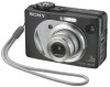
DSC-W1/W12 HR6 (size AA) Ni-MH batteries (W1: 2, W12: 4) (not supplied) Battery case (W1: 1, W12: 2) 3-074-757-01 Battery charger (BC-CS2) (1) 0 1-477-814-11 (US, CND, JE, J) 0 1-477-814-21 (AEP, UK, E, HK, AUS) 0 1-477-814-31 (CH, ...) 0 1-790-732-12 (JE, J) 0 1-827-945-11 (AUS) USB cable (1) 1-827-038-11 A/V connecting cable (1) 1-824-111-11 Wrist strap (1) 2-050-981-01 (W1: Silver) 2-050-981-11 (W1: Black/W12) "Memory Stick" (32MB) (1) (not supplied) Conversion Adaptor (1) 0 1-569-007-11 (E) 0 1-573-856-12 (JE) CD-ROM (SPVD-012 USB driver) (1) 3-091-338...
DSC-W1/W12 HR6 (size AA) Ni-MH batteries (W1: 2, W12: 4) (not supplied) Battery case (W1: 1, W12: 2) 3-074-757-01 Battery charger (BC-CS2) (1) 0 1-477-814-11 (US, CND, JE, J) 0 1-477-814-21 (AEP, UK, E, HK, AUS) 0 1-477-814-31 (CH, ...) 0 1-790-732-12 (JE, J) 0 1-827-945-11 (AUS) USB cable (1) 1-827-038-11 A/V connecting cable (1) 1-824-111-11 Wrist strap (1) 2-050-981-01 (W1: Silver) 2-050-981-11 (W1: Black/W12) "Memory Stick" (32MB) (1) (not supplied) Conversion Adaptor (1) 0 1-569-007-11 (E) 0 1-573-856-12 (JE) CD-ROM (SPVD-012 USB driver) (1) 3-091-338...

Service Manual
Page 48
... with mark 0 are critical for APPLICATION) (J) The components identified by mark 0 or dotted line with part number specified. DSC-W1/W12 - 3 - Les composants identifiés par une marque 0 sont critiques pour la sécurité. • Addition of Argentine Model...827-945-11 (AUS) 0 1-783-952-21 (AR) ) USB cable (1) 1-827-038-11 A/V connecting cable (1) 1-824-111-11 Wrist strap (1) 2-050-981-01 (W1: Silver) 2-050-981-11 (W1: Black/W12) "Memory Stick" (32MB) (1) (not supplied) Conversion Adaptor (1) 0 1-569-007-11 (E) 0 1-573-856-12 (JE) • Abbreviation AR : Argentine model ...
... with mark 0 are critical for APPLICATION) (J) The components identified by mark 0 or dotted line with part number specified. DSC-W1/W12 - 3 - Les composants identifiés par une marque 0 sont critiques pour la sécurité. • Addition of Argentine Model...827-945-11 (AUS) 0 1-783-952-21 (AR) ) USB cable (1) 1-827-038-11 A/V connecting cable (1) 1-824-111-11 Wrist strap (1) 2-050-981-01 (W1: Silver) 2-050-981-11 (W1: Black/W12) "Memory Stick" (32MB) (1) (not supplied) Conversion Adaptor (1) 0 1-569-007-11 (E) 0 1-573-856-12 (JE) • Abbreviation AR : Argentine model ...
Service Manual
Page 54
...) (J) The components identified by mark 0 or dotted line with part number specified. DSC-W1/W12 - 3 - Checking supplied accessories. (Service manual page 5-15) HR6 (size AA) Ni-MH batteries (W1: 2, W12: 4) (not supplied) Battery case (W1: 1, W12: 2) 3-074-757-01 Battery charger (BC-CS2) (1) 0 1-477... 0 1-783-952-21 (AR) ) USB cable (1) 1-827-038-11 A/V connecting cable (1) 1-824-111-11 Wrist strap (1) 2-050-981-01 (W1: Silver) 2-050-981-11 (W1: Black/W12) "Memory Stick" (32MB) (1) (not supplied) Conversion Adaptor (1) 0 1-569-007-11 (E) 0 1-573-856-12 (JE) • Abbreviation AR...
...) (J) The components identified by mark 0 or dotted line with part number specified. DSC-W1/W12 - 3 - Checking supplied accessories. (Service manual page 5-15) HR6 (size AA) Ni-MH batteries (W1: 2, W12: 4) (not supplied) Battery case (W1: 1, W12: 2) 3-074-757-01 Battery charger (BC-CS2) (1) 0 1-477... 0 1-783-952-21 (AR) ) USB cable (1) 1-827-038-11 A/V connecting cable (1) 1-824-111-11 Wrist strap (1) 2-050-981-01 (W1: Silver) 2-050-981-11 (W1: Black/W12) "Memory Stick" (32MB) (1) (not supplied) Conversion Adaptor (1) 0 1-569-007-11 (E) 0 1-573-856-12 (JE) • Abbreviation AR...

Service Manual
Page 58
... adj. CCD white defect compensation check CCD black defect compensation check Strobe adj. AWB 3200K standard data input AWB 5800K standard data input CAMERA adjustment 3 AWB 5800K check z zz zz... z z AWB 3200K check CCD linearity check Color reproduction adj. zz zz zz z V-COM adj. z zz zz z z F No. CAMERA adjustment 4 Auto focus illumination check zz zzz zz z z LCD initial data input VCO adj. Note 1: The automatic Adjustment Program does not support the "Initialization of Camera System Adjustment. DSC-W1...
... adj. CCD white defect compensation check CCD black defect compensation check Strobe adj. AWB 3200K standard data input AWB 5800K standard data input CAMERA adjustment 3 AWB 5800K check z zz zz... z z AWB 3200K check CCD linearity check Color reproduction adj. zz zz zz z V-COM adj. z zz zz z z F No. CAMERA adjustment 4 Auto focus illumination check zz zzz zz z z LCD initial data input VCO adj. Note 1: The automatic Adjustment Program does not support the "Initialization of Camera System Adjustment. DSC-W1...

Service Manual
Page 60
Color monitor Vectorscope Video (yellow) Terminated 75 Ω PC OS: Windows 98/98SE/Me/2000/XP Audio (Black) RAM: 256MB or more recommended USB: 2.0 recommended (also compatible with 1.1) Two connectors are required. To USB connector USB cable (1-827-038-11) To USB connector ... USB connector To A/V OUT jack Insert the Memory Stick. Preparations 1) Connect the equipment for adjustments according to Fig. 6-1-3. 2) Start up the application for adjustment (SEUS). DSC-W1/W12 1-1-2.
Color monitor Vectorscope Video (yellow) Terminated 75 Ω PC OS: Windows 98/98SE/Me/2000/XP Audio (Black) RAM: 256MB or more recommended USB: 2.0 recommended (also compatible with 1.1) Two connectors are required. To USB connector USB cable (1-827-038-11) To USB connector ... USB connector To A/V OUT jack Insert the Memory Stick. Preparations 1) Connect the equipment for adjustments according to Fig. 6-1-3. 2) Start up the application for adjustment (SEUS). DSC-W1/W12 1-1-2.

Service Manual
Page 62
... internal. (Fig. 6-1-6) woody board A woody board B woody board A woody board B woody board C Fig. 6-1-6 6-6 If it is required to woody board C. 4) Assemble so that the black sides and the background paper side of 15 mm thickness. woody board A (2) 400 mm woody board B (2) 370 mm woody board C (1) 700 mm 513 mm 513... mm 700 mm 730 mm 700 mm Fig. 6-1-5 2) Apply black mat paint to one side of woody board A and B. 3) Attach background paper (J-2501-130-A) to provide an accurate flash adjustment...
... internal. (Fig. 6-1-6) woody board A woody board B woody board A woody board B woody board C Fig. 6-1-6 6-6 If it is required to woody board C. 4) Assemble so that the black sides and the background paper side of 15 mm thickness. woody board A (2) 400 mm woody board B (2) 370 mm woody board C (1) 700 mm 513 mm 513... mm 700 mm 730 mm 700 mm Fig. 6-1-5 2) Apply black mat paint to one side of woody board A and B. 3) Attach background paper (J-2501-130-A) to provide an accurate flash adjustment...

Service Manual
Page 69
... Input AWB 5800K Standard Data Input AWB 5800K Check AWB 3200K Check CCD Linearity Check Color Reproduction Adj. Adjustment Items of Camera System Adjustment The adjustment items of Camera System Adjustment. CCD White Defect Compensation Check CCD Black Defect Compensation Check Strobe Adj. The Automatic Adjustment Program divides the adjustment items into four... chart (Standard picture frame) Clear chart (Standard picture frame) Clear chart (Standard picture frame) Filter C14 for the subject and filter as listed in Table 6-1-3. DSC-W1/W12 1-4-2.
... Input AWB 5800K Standard Data Input AWB 5800K Check AWB 3200K Check CCD Linearity Check Color Reproduction Adj. Adjustment Items of Camera System Adjustment The adjustment items of Camera System Adjustment. CCD White Defect Compensation Check CCD Black Defect Compensation Check Strobe Adj. The Automatic Adjustment Program divides the adjustment items into four... chart (Standard picture frame) Clear chart (Standard picture frame) Clear chart (Standard picture frame) Filter C14 for the subject and filter as listed in Table 6-1-3. DSC-W1/W12 1-4-2.

Service Manual
Page 70
... between it and the front of lens of camera is less than 3.5 A Fig. 6-1-17 Red (+) Black (-) Yellow (SENS +) White (SENS -) Black (GND) Need not connected Fig. 6-1-18 6-14 Data Setting during Camera Adj.", the following message is installed as shown... displayed. Adjusting Method 1. Data Setting during Camera Adj." ure. Flange Back Adj. 3. Release of Data Setting during Camera Adj.". 3) Upon successful completion of Flange Back Adj.". DSC-W1/W12 1-4-3. Data Setting during Camera Adj. [Adjusting method] 1) Click the [CAMERA Adjustment 1 Start] button. 2) The Automatic...
... between it and the front of lens of camera is less than 3.5 A Fig. 6-1-17 Red (+) Black (-) Yellow (SENS +) White (SENS -) Black (GND) Need not connected Fig. 6-1-18 6-14 Data Setting during Camera Adj.", the following message is installed as shown... displayed. Adjusting Method 1. Data Setting during Camera Adj." ure. Flange Back Adj. 3. Release of Data Setting during Camera Adj.". 3) Upon successful completion of Flange Back Adj.". DSC-W1/W12 1-4-3. Data Setting during Camera Adj. [Adjusting method] 1) Click the [CAMERA Adjustment 1 Start] button. 2) The Automatic...

Service Manual
Page 74
DSC-W1/W12 5. Picture Frame Setting 3. Light Value Adj. 6. AWB 3200K Check 10. CCD Black Defect Compensation Check 14. Data Set- Fig. 6-1-32 6) Click the [OK] button, and the "7. AWB 5800K Standard Data Input" and "8. CCD Linearity Check" will ... completion of the "AWB 5800K Check", the following message is displayed. Mechanical Shutter Adj. 5. AWB 3200K Standard Data Input 7. CCD Linearity Check 11. ting during Camera Adj. 2. AWB 5800K Check" will be executed. 7) Upon successful completion of the "AWB 3200K Check", the following message is displayed. F No. AWB 5800K ...
DSC-W1/W12 5. Picture Frame Setting 3. Light Value Adj. 6. AWB 3200K Check 10. CCD Black Defect Compensation Check 14. Data Set- Fig. 6-1-32 6) Click the [OK] button, and the "7. AWB 5800K Standard Data Input" and "8. CCD Linearity Check" will ... completion of the "AWB 5800K Check", the following message is displayed. Mechanical Shutter Adj. 5. AWB 3200K Standard Data Input 7. CCD Linearity Check 11. ting during Camera Adj. 2. AWB 5800K Check" will be executed. 7) Upon successful completion of the "AWB 3200K Check", the following message is displayed. F No. AWB 5800K ...

Service Manual
Page 75
... the message. Check on the vectorscope R-Y MG R YE W B-Y B G CY Fig. 6-1-35 11) Upon successful completion of Data Setting during Camera Adj." Change the chart in accordance with the message. Burst Position Fig. 6-1-38 Fig. 6-1-36 12) Click the [OK] button, and the ... of all items of the CAMERA Adjustment 3, the following message is displayed. pensation Check", "13. CCD Black Defect Compensation Check" and "14. Click the [OK] button. Color Reproduction Adj.", the following message is displayed. Fig. 6-1-37 6-19 Release of "11. DSC-W1/W12 10) Click the [OK...
... the message. Check on the vectorscope R-Y MG R YE W B-Y B G CY Fig. 6-1-35 11) Upon successful completion of Data Setting during Camera Adj." Change the chart in accordance with the message. Burst Position Fig. 6-1-38 Fig. 6-1-36 12) Click the [OK] button, and the ... of all items of the CAMERA Adjustment 3, the following message is displayed. pensation Check", "13. CCD Black Defect Compensation Check" and "14. Click the [OK] button. Color Reproduction Adj.", the following message is displayed. Fig. 6-1-37 6-19 Release of "11. DSC-W1/W12 10) Click the [OK...


