
Service Manual
Page 1
...Model Argentine Model Brazilian Model Tourist Model Japanese Model DSC-W1/W12 AEP Model UK Model E Model Chinese Model Korea Model SPECIFICATIONS SERVICE NOTE DISASSEMBLY BLOCK DIAGRAMS PRINTED WIRING BOARDS FRAME SCHEMATIC DIAGRAM REPAIR PARTS LIST SCHEMATIC DIAGRAMS • For ADJUSTMENTS (... 4-9 to 4-28 circuit board replacement service and not intended repair inside Printed wiring board Pages 4-39 to SERVICE MANUAL, LEVEL 1 (987673641.pdf). • Reference No. service manual Level 3. DIGITAL STILL CAMERA Electrical parts list Pages 5-7 to 5-8 Therefore, schematic diagram,...
...Model Argentine Model Brazilian Model Tourist Model Japanese Model DSC-W1/W12 AEP Model UK Model E Model Chinese Model Korea Model SPECIFICATIONS SERVICE NOTE DISASSEMBLY BLOCK DIAGRAMS PRINTED WIRING BOARDS FRAME SCHEMATIC DIAGRAM REPAIR PARTS LIST SCHEMATIC DIAGRAMS • For ADJUSTMENTS (... 4-9 to 4-28 circuit board replacement service and not intended repair inside Printed wiring board Pages 4-39 to SERVICE MANUAL, LEVEL 1 (987673641.pdf). • Reference No. service manual Level 3. DIGITAL STILL CAMERA Electrical parts list Pages 5-7 to 5-8 Therefore, schematic diagram,...

Service Manual
Page 3
...ROS SONT DONNÉS DANS CE MANUEL OU DANS LES SUPPÉMENTS PUBLIÉS PAR SONY. Point them out to use of the soldering iron around 270˚C during a previous repair. Check the B+ voltage to see it is best to the customer and recommend their particular ... problem, perform the following characteristics. • Unleaded solder melts at the values specified. 6. Look for unsoldered or poorly-soldered connections. DSC-W1/W12 SAFETY-RELATED COMPONENT WARNING!! Ordinary soldering irons can be used but unleaded solder may not come printed with the lead free mark due...
...ROS SONT DONNÉS DANS CE MANUEL OU DANS LES SUPPÉMENTS PUBLIÉS PAR SONY. Point them out to use of the soldering iron around 270˚C during a previous repair. Check the B+ voltage to see it is best to the customer and recommend their particular ... problem, perform the following characteristics. • Unleaded solder melts at the values specified. 6. Look for unsoldered or poorly-soldered connections. DSC-W1/W12 SAFETY-RELATED COMPONENT WARNING!! Ordinary soldering irons can be used but unleaded solder may not come printed with the lead free mark due...
Service Manual
Page 4
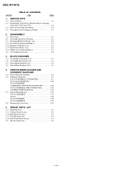
... Diagram (1/2 3-1 3-2. PRINTED WIRING BOARDS AND SCHEMATIC DIAGRAMS 4-1. Side Frame Block Section 5-5 5-2. DISASSEMBLY 2-1. Circuit Boards Location 2-8 3. Note for Repair 1-1 1-2. REPAIR PARTS LIST 5-1. Lens Block Section 5-4 5-1-4. Power Block Diagram (1/2 3-5 3-4. Peel Off Old Ornamental Ring A 2-5 2-3-2. Frame Schematic Diagram 4-1 ...35 CD-507 FLEXIBLE 4-37 ST-100 4-49 ST-101 FLEXIBLE 4-50 US-011 FLEXIBLE 4-51 4-4. DSC-W1/W12 Section TABLE OF CONTENTS Title Page 1. SERVICE NOTE 1-1. Note in Lens Frame Installation 1-2 1-4. Install New Barrier Assy 2-6...
... Diagram (1/2 3-1 3-2. PRINTED WIRING BOARDS AND SCHEMATIC DIAGRAMS 4-1. Side Frame Block Section 5-5 5-2. DISASSEMBLY 2-1. Circuit Boards Location 2-8 3. Note for Repair 1-1 1-2. REPAIR PARTS LIST 5-1. Lens Block Section 5-4 5-1-4. Power Block Diagram (1/2 3-5 3-4. Peel Off Old Ornamental Ring A 2-5 2-3-2. Frame Schematic Diagram 4-1 ...35 CD-507 FLEXIBLE 4-37 ST-100 4-49 ST-101 FLEXIBLE 4-50 US-011 FLEXIBLE 4-51 4-4. DSC-W1/W12 Section TABLE OF CONTENTS Title Page 1. SERVICE NOTE 1-1. Note in Lens Frame Installation 1-2 1-4. Install New Barrier Assy 2-6...

Service Manual
Page 5
... W (1-215-869-11). Therefore, the remaining voltage must be left inside) When installing a connector, don't press down at the terminal. SECTION 1 SERVICE NOTE DSC-W1/W12 1-1. Capacitor ST kemikon sheet ST-101 R:1 kΩ/1 W (Part code: 1-215-869-11) Wrap insulating tape. 1-1 Wrap insulating tape fully around the... the Capacitor Short-circuit between the positive and the negative terminals of connector. The electric shock is caused by hand. NOTE FOR REPAIR Make sure that a wire is simply turned off at the point. (Be careful or some pieces of gilt may be discharged as described...
... W (1-215-869-11). Therefore, the remaining voltage must be left inside) When installing a connector, don't press down at the terminal. SECTION 1 SERVICE NOTE DSC-W1/W12 1-1. Capacitor ST kemikon sheet ST-101 R:1 kΩ/1 W (Part code: 1-215-869-11) Wrap insulating tape. 1-1 Wrap insulating tape fully around the... the Capacitor Short-circuit between the positive and the negative terminals of connector. The electric shock is caused by hand. NOTE FOR REPAIR Make sure that a wire is simply turned off at the point. (Be careful or some pieces of gilt may be discharged as described...

Service Manual
Page 21
... Link • All capacitors are measured between the measurement points and ground when camera shoots color bar chart of chip. kΩ=1000 Ω, MΩ=1000 kΩ...Les composants identifiés par une marque 0 sont critiques pour la sécurité. SCHEMATIC DIAGRAMS DSC-W1/W12 4-2. They are 1/10 W unless otherwise noted. H Yellow Cyan Green White Magenta Red Blue ... a and the Fig. pF : µ µF. 50 V or less are not indicated except for repair. • A: VIDEO SIGNAL (ANALOG) • A: AUDIO SIGNAL (ANALOG) • A: VIDEO/AUDIO SIGNAL...
... Link • All capacitors are measured between the measurement points and ground when camera shoots color bar chart of chip. kΩ=1000 Ω, MΩ=1000 kΩ...Les composants identifiés par une marque 0 sont critiques pour la sécurité. SCHEMATIC DIAGRAMS DSC-W1/W12 4-2. They are 1/10 W unless otherwise noted. H Yellow Cyan Green White Magenta Red Blue ... a and the Fig. pF : µ µF. 50 V or less are not indicated except for repair. • A: VIDEO SIGNAL (ANALOG) • A: AUDIO SIGNAL (ANALOG) • A: VIDEO/AUDIO SIGNAL...

Service Manual
Page 35
REPAIR PARTS LIST NOTE: Characters A to Z of the electrical parts list indicate location of exploded views in which the desired part is shown. DSC-W1/W12 NOTE 5. Link EXPLODED VIEWS A CABINET BLOCK SECTION B MAIN BLOCK SECTION C LENS BLOCK SECTION D SIDE FRAME BLOCK SECTION Link ELECTRICAL PARTS LIST CD-507 FLEXIBLE BOARD C ST-101 FLEXIBLE BOARD B ST-100 BOARD B US-011 FLEXIBLE BOARD D ACCESSORIES
REPAIR PARTS LIST NOTE: Characters A to Z of the electrical parts list indicate location of exploded views in which the desired part is shown. DSC-W1/W12 NOTE 5. Link EXPLODED VIEWS A CABINET BLOCK SECTION B MAIN BLOCK SECTION C LENS BLOCK SECTION D SIDE FRAME BLOCK SECTION Link ELECTRICAL PARTS LIST CD-507 FLEXIBLE BOARD C ST-101 FLEXIBLE BOARD B ST-100 BOARD B US-011 FLEXIBLE BOARD D ACCESSORIES

Service Manual
Page 36
... 0 are seldom required for safety. Ne les remplacer que par une pièce portant le numéro spécifié. 5-1 REPAIR PARTS LIST SECTION 5 REPAIR PARTS LIST DSC-W1/W12 NOTE: • -XX, -X mean standardized parts, so they may be anticipated when ordering these items. • The mechanical parts with part...
... 0 are seldom required for safety. Ne les remplacer que par une pièce portant le numéro spécifié. 5-1 REPAIR PARTS LIST SECTION 5 REPAIR PARTS LIST DSC-W1/W12 NOTE: • -XX, -X mean standardized parts, so they may be anticipated when ordering these items. • The mechanical parts with part...

Service Manual
Page 37
REPAIR PARTS LIST ns 7 6 MIC901 5 3 8 9 10 Main block section 11 (See page 5-3.) 4 5 2 1 5 12 5 Ref. EXPLODED VIEWS 5-1-1. CABINET BLOCK SECTION ns: not supplied 5. Description 3-092-127-01 COVER (L), SIDE (W1: SILVER) 3-092-127-11 COVER (L), SIDE (W1: BLACK/W12) X-2021-015-1 CABINET (B), REAR ASSY (W12) X-2021-375-1 CABINET (B), REAR ASSY (W1...: BLACK) X-3954-544-1 CABINET, REAR ASSY (W1: SILVER) 5 3-090-976-11 ACE, LOCK M1.7 (W1: SILVER) 5 3-090-976-61 ACE, LOCK M1.7 (W1...CABINET (FRONT) ASSY (B) (W1: BLACK/W12) X-3954-542-1 CABINET (FRONT) ASSY (W1: SILVER) 3-092-059-...
REPAIR PARTS LIST ns 7 6 MIC901 5 3 8 9 10 Main block section 11 (See page 5-3.) 4 5 2 1 5 12 5 Ref. EXPLODED VIEWS 5-1-1. CABINET BLOCK SECTION ns: not supplied 5. Description 3-092-127-01 COVER (L), SIDE (W1: SILVER) 3-092-127-11 COVER (L), SIDE (W1: BLACK/W12) X-2021-015-1 CABINET (B), REAR ASSY (W12) X-2021-375-1 CABINET (B), REAR ASSY (W1...: BLACK) X-3954-544-1 CABINET, REAR ASSY (W1: SILVER) 5 3-090-976-11 ACE, LOCK M1.7 (W1: SILVER) 5 3-090-976-61 ACE, LOCK M1.7 (W1...CABINET (FRONT) ASSY (B) (W1: BLACK/W12) X-3954-542-1 CABINET (FRONT) ASSY (W1: SILVER) 3-092-059-...

Service Manual
Page 38
...) 1-478-645-21 CONTROL SWITCH BLOCK (W1: BLACK/W12) 3-092-129-01 SHEET, ST KEMIKONN A-7079-044-A ST-101 FLEXIBLE BOARD, COMPLETE (including ST-100 board) 1-478-621-11 FLASH UNIT 3-092-134-01 SHEET (F), ST KEMIKONN 3-092-123-01 HOLDER, CONDENSER Ref. REPAIR PARTS LIST 5-1-2. No. 51 51 52 53 0... 54 55 56 Part No. MAIN BLOCK SECTION 52 51 53 (including ST-100 board) C102 (Note) C103 (Note) 54 55 56 ST-101 Side frame block section (See page 5-5.) DSC-W1/W12 Lens block section (See page 5-4.)...
...) 1-478-645-21 CONTROL SWITCH BLOCK (W1: BLACK/W12) 3-092-129-01 SHEET, ST KEMIKONN A-7079-044-A ST-101 FLEXIBLE BOARD, COMPLETE (including ST-100 board) 1-478-621-11 FLASH UNIT 3-092-134-01 SHEET (F), ST KEMIKONN 3-092-123-01 HOLDER, CONDENSER Ref. REPAIR PARTS LIST 5-1-2. No. 51 51 52 53 0... 54 55 56 Part No. MAIN BLOCK SECTION 52 51 53 (including ST-100 board) C102 (Note) C103 (Note) 54 55 56 ST-101 Side frame block section (See page 5-5.) DSC-W1/W12 Lens block section (See page 5-4.)...

Service Manual
Page 39
LENS BLOCK SECTION ns: not supplied 5. REPAIR PARTS LIST 112 ns (including CD-507 flexible board and IC101) (Note 2) 111 110 109 108 CD-507 101 104 (Note 1) 103 (Note 1) 107 106 ... change Ref. No. 102, 103 and 104. (Note 2) Be sure to read "Precuations for Replacement of Barrier Assy" on page 4-8 when changing the CCD imager. DSC-W1/W12 5-1-3. Ref. No. 101 102 103 104 105 Part No. No. 107 108 109 110 111 Part No. Description 8-848-772-01 LSV-890A 3-091...
LENS BLOCK SECTION ns: not supplied 5. REPAIR PARTS LIST 112 ns (including CD-507 flexible board and IC101) (Note 2) 111 110 109 108 CD-507 101 104 (Note 1) 103 (Note 1) 107 106 ... change Ref. No. 102, 103 and 104. (Note 2) Be sure to read "Precuations for Replacement of Barrier Assy" on page 4-8 when changing the CCD imager. DSC-W1/W12 5-1-3. Ref. No. 101 102 103 104 105 Part No. No. 107 108 109 110 111 Part No. Description 8-848-772-01 LSV-890A 3-091...

Service Manual
Page 40
... (W1: BLACK/W12) 1-478-463-11 BLOCK, LIGHT GUIDE PLATE 1-793-620-41 JACK (AV OUT (MONO)) 1-817-331-11 DC JACK 5P (DC IN) LCD901 8-753-217-37 ACX326CM-J SP901 1-825-219-21 SPEAKER (1.3CM) 5-5 5. Les composants identifiés par une marque 0 sont critiques pour la sécurité. REPAIR PARTS... LIST DSC-W1/W12 5-1-4. Ne les remplacer que par une pièce portant le numéro spécifié.
... (W1: BLACK/W12) 1-478-463-11 BLOCK, LIGHT GUIDE PLATE 1-793-620-41 JACK (AV OUT (MONO)) 1-817-331-11 DC JACK 5P (DC IN) LCD901 8-753-217-37 ACX326CM-J SP901 1-825-219-21 SPEAKER (1.3CM) 5-5 5. Les composants identifiés par une marque 0 sont critiques pour la sécurité. REPAIR PARTS... LIST DSC-W1/W12 5-1-4. Ne les remplacer que par une pièce portant le numéro spécifié.

Service Manual
Page 55
...REPAIR PARTS LIST EXPLODED VIEWS ELECTRICAL PARTS LEVEL 3 ✕ ✕ ✕ CH-146, SY-102, SW-422, MS-204, MS-205, FLEXIBLE, JK-263, SP-045 FLEXIBLE ✕ a (CH-146, SY-102, SW-422, MS-204, MS-205, FLEXIBLE, JK-263, SP-045 FLEXIBLE) 9-876-736-51 Sony... EMCS Co. 2004D0500-1 ©2004.4 Published by DI Technical Support Section DSC-W1/W12 Ver 1.0 2004. 04 Revision History SECTION 6 ADJUSTMENTS Link Before starting adjustments Adjusting items when replacing main parts and boards CAMERA SECTION ADJUSTMENTS PREPARATIONS BEFORE ADJUSTMENTS ...
...REPAIR PARTS LIST EXPLODED VIEWS ELECTRICAL PARTS LEVEL 3 ✕ ✕ ✕ CH-146, SY-102, SW-422, MS-204, MS-205, FLEXIBLE, JK-263, SP-045 FLEXIBLE ✕ a (CH-146, SY-102, SW-422, MS-204, MS-205, FLEXIBLE, JK-263, SP-045 FLEXIBLE) 9-876-736-51 Sony... EMCS Co. 2004D0500-1 ©2004.4 Published by DI Technical Support Section DSC-W1/W12 Ver 1.0 2004. 04 Revision History SECTION 6 ADJUSTMENTS Link Before starting adjustments Adjusting items when replacing main parts and boards CAMERA SECTION ADJUSTMENTS PREPARATIONS BEFORE ADJUSTMENTS ...

Service Manual
Page 57
...the respective items of the machine that is stored in which a board is going to a personal computer. SECTION 6 ADJUSTMENTS DSC-W1/W12 Before starting repair) PC PC (Machine after a board is replaced. (Machine before starting adjustment EVR Data Re-writing Procedure When Replacing Board The... data that is replaced) Save the EVR data to be repaired. Perform either procedure 1 or procedure 2 or procedure 3 when replacing board. Install the removed flash memory to be removed or ...
...the respective items of the machine that is stored in which a board is going to a personal computer. SECTION 6 ADJUSTMENTS DSC-W1/W12 Before starting repair) PC PC (Machine after a board is replaced. (Machine before starting adjustment EVR Data Re-writing Procedure When Replacing Board The... data that is replaced) Save the EVR data to be repaired. Perform either procedure 1 or procedure 2 or procedure 3 when replacing board. Install the removed flash memory to be removed or ...

Service Manual
Page 82
... set data: 00. 2. In this case, the Test mode is not released even if the camera is turned off, thus requiring extreme care. • After completing adjustments/repairs, release the data setting. 1) Select page: 00, address: 01, and set data: 01....0 1 0 0 0 1 2 0 0 1 0 3 0 0 1 1 4 0 1 0 0 5 0 1 0 1 6 0 1 1 0 7 0 1 1 1 A 8 1 0 0 0 9 1 0 0 1 A 1 0 1 0 B 1 0 1 1 C 1 1 0 0 D 1 1 0 1 B E 1 1 1 0 F 1 1 1 1 Example: If the displayed data is recorded in non-volatile memory by saving data. DSC-W1/W12 6-2.
... set data: 00. 2. In this case, the Test mode is not released even if the camera is turned off, thus requiring extreme care. • After completing adjustments/repairs, release the data setting. 1) Select page: 00, address: 01, and set data: 01....0 1 0 0 0 1 2 0 0 1 0 3 0 0 1 1 4 0 1 0 0 5 0 1 0 1 6 0 1 1 0 7 0 1 1 1 A 8 1 0 0 0 9 1 0 0 1 A 1 0 1 0 B 1 0 1 1 C 1 1 0 0 D 1 1 0 1 B E 1 1 1 0 F 1 1 1 1 Example: If the displayed data is recorded in non-volatile memory by saving data. DSC-W1/W12 6-2.


