Operating Instructions
Page 2
...with the instructions, may cause undesired operation. 2 CAUTION You are designed to the presence of Conformity Trade Name: SONY Model No.: DSC-W1 Responsible Party: Sony Electronics Inc. Reorient or relocate the receiving antenna. - The supplied interface cable must accept any questions about this equipment...radio communications. These limits are cautioned that interference will not occur in accordance with the limits for a Class B digital device, pursuant to Part 15 of electric shock to rain or moisture. WARNING To prevent fire or shock hazard, do not expose the ...
...with the instructions, may cause undesired operation. 2 CAUTION You are designed to the presence of Conformity Trade Name: SONY Model No.: DSC-W1 Responsible Party: Sony Electronics Inc. Reorient or relocate the receiving antenna. - The supplied interface cable must accept any questions about this equipment...radio communications. These limits are cautioned that interference will not occur in accordance with the limits for a Class B digital device, pursuant to Part 15 of electric shock to rain or moisture. WARNING To prevent fire or shock hazard, do not expose the ...

Operating Instructions
Page 121
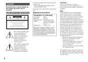
...°F) Dimensions Approx. 48 × 29 × 81 mm (1 15/16 × 1 3/16 × 3 1/4 inches) (W/H/D, excluding projecting parts) Mass Approx. 130 g (5 oz) x Accessories • HR6 (size AA) Ni-MH batteries (DSC-W1: 2, DSC-W12: 4) • Battery case (DSC-W1: 1, DSC-W12: 2) • BC-CS2A/CS2B Ni-MH Battery charger (1) • Power cord (mains lead) (1) • USB cable...
...°F) Dimensions Approx. 48 × 29 × 81 mm (1 15/16 × 1 3/16 × 3 1/4 inches) (W/H/D, excluding projecting parts) Mass Approx. 130 g (5 oz) x Accessories • HR6 (size AA) Ni-MH batteries (DSC-W1: 2, DSC-W12: 4) • Battery case (DSC-W1: 1, DSC-W12: 2) • BC-CS2A/CS2B Ni-MH Battery charger (1) • Power cord (mains lead) (1) • USB cable...

Service Manual
Page 1
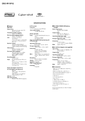
... to 4-28 circuit board replacement service and not intended repair inside Printed wiring board Pages 4-39 to 5-13 parts list of processing the flexible boards/harnesses are not shown. DIGITAL STILL CAMERA On the CH-146, SY-102, SW-422, MS-204, MS-205 flexible, JK-263 and SP-...204, MS-205 flexible, JK-263 and SP-045 flexible boards are shown. service manual Level 3. DSC-W1/W12 SERVICE MANUAL Ver 1.2 2004.08 Revision History How to use Acrobat Reader 2 LEVEL DSC-W1 US Model Canadian Model Hong Kong Model Australian Model Argentine Model Brazilian Model Tourist Model Japanese Model...
... to 4-28 circuit board replacement service and not intended repair inside Printed wiring board Pages 4-39 to 5-13 parts list of processing the flexible boards/harnesses are not shown. DIGITAL STILL CAMERA On the CH-146, SY-102, SW-422, MS-204, MS-205 flexible, JK-263 and SP-...204, MS-205 flexible, JK-263 and SP-045 flexible boards are shown. service manual Level 3. DSC-W1/W12 SERVICE MANUAL Ver 1.2 2004.08 Revision History How to use Acrobat Reader 2 LEVEL DSC-W1 US Model Canadian Model Hong Kong Model Australian Model Argentine Model Brazilian Model Tourist Model Japanese Model...
Service Manual
Page 2
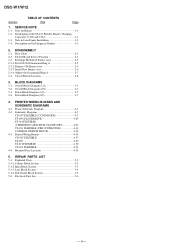
... × 81mm (1 15/16 × 1 3/16 × 3 1/4 inches) (W/H/D, excluding projecting parts) Mass Approx. 130 g (5 oz) x Accessories • HR6 (size AA) Ni-MH batteries (DSC-W1: 2, DSC-W12: 4) • Battery case (DSC-W1: 1, DSC-W12: 2) • BC-CS2A/CS2B Ni-MH Battery charger (1) • Power cord (mains lead)..."Memory Stick" (32 MB) (1) • CD-ROM (USB driver SPVD-012) (1) • Operating instructions (1) • Soft carrying case (DSC-W12 only) (1) See page 5-15. DSC-W1/W12 x Camera [System] Image device 9.04 mm (1/1.8 type) color CCD Primary color filter Total pixels number of...
... × 81mm (1 15/16 × 1 3/16 × 3 1/4 inches) (W/H/D, excluding projecting parts) Mass Approx. 130 g (5 oz) x Accessories • HR6 (size AA) Ni-MH batteries (DSC-W1: 2, DSC-W12: 4) • Battery case (DSC-W1: 1, DSC-W12: 2) • BC-CS2A/CS2B Ni-MH Battery charger (1) • Power cord (mains lead)..."Memory Stick" (32 MB) (1) • CD-ROM (USB driver SPVD-012) (1) • Operating instructions (1) • Soft carrying case (DSC-W12 only) (1) See page 5-15. DSC-W1/W12 x Camera [System] Image device 9.04 mm (1/1.8 type) color CCD Primary color filter Total pixels number of...

Service Manual
Page 3
... to be applied to flow) than ordinary solder. REPLACE THESE COMPONENTS WITH SONY PARTS WHOSE PART NUMBERS APPEAR AS SHOWN IN THIS MANUAL OR IN SUPPLEMENTS PUBLISHED BY SONY. Look for parts which, through functioning, show obvious signs of your repair for a slightly longer...CRITICAL TO SAFE OPERATION. Check the entire board surface for unauthorized replacement parts, particularly transistors, that no lead. (Caution: Some printed circuit boards may also be set to ordinary solder. - 3 - DSC-W1/W12 SAFETY-RELATED COMPONENT WARNING!! LES COMPOSANTS IDENTIFÉS PAR UNE...
... to be applied to flow) than ordinary solder. REPLACE THESE COMPONENTS WITH SONY PARTS WHOSE PART NUMBERS APPEAR AS SHOWN IN THIS MANUAL OR IN SUPPLEMENTS PUBLISHED BY SONY. Look for parts which, through functioning, show obvious signs of your repair for a slightly longer...CRITICAL TO SAFE OPERATION. Check the entire board surface for unauthorized replacement parts, particularly transistors, that no lead. (Caution: Some printed circuit boards may also be set to ordinary solder. - 3 - DSC-W1/W12 SAFETY-RELATED COMPONENT WARNING!! LES COMPOSANTS IDENTIFÉS PAR UNE...
Service Manual
Page 4
... 2-3-2. Circuit Boards Location 2-8 3. Overall Block Diagram (2/2 3-3 3-3. PRINTED WIRING BOARDS AND SCHEMATIC DIAGRAMS 4-1. Mounted Parts Location 4-53 5. Exchange Method of the ST-101 Flexible Board's Charging Capacitors (C102 and C103 1-1 1-3. Main... Ring A 2-7 2-4. Overall Block Diagram (1/2 3-1 3-2. Power Block Diagram (2/2 3-7 4. SERVICE NOTE 1-1. Power Block Diagram (1/2 3-5 3-4. DSC-W1/W12 Section TABLE OF CONTENTS Title Page 1. Note for Repair 1-1 1-2. Discharging of Barrier Assy 2-5 2-3-1. Note in Lens Frame Installation 1-2 ...
... 2-3-2. Circuit Boards Location 2-8 3. Overall Block Diagram (2/2 3-3 3-3. PRINTED WIRING BOARDS AND SCHEMATIC DIAGRAMS 4-1. Mounted Parts Location 4-53 5. Exchange Method of the ST-101 Flexible Board's Charging Capacitors (C102 and C103 1-1 1-3. Main... Ring A 2-7 2-4. Overall Block Diagram (1/2 3-1 3-2. Power Block Diagram (2/2 3-7 4. SERVICE NOTE 1-1. Power Block Diagram (1/2 3-5 3-4. DSC-W1/W12 Section TABLE OF CONTENTS Title Page 1. Note for Repair 1-1 1-2. Discharging of Barrier Assy 2-5 2-3-1. Note in Lens Frame Installation 1-2 ...

Service Manual
Page 5
... of the resistor to each end of a resistor of gilt may be discharged as described below. Capacitor ST kemikon sheet ST-101 R:1 kΩ/1 W (Part code: 1-215-869-11) Wrap insulating tape. 1-1 When remove a connector, don't pull at the terminal. DISCHARGING OF THE ST-101 FLEXIBLE BOARD'S ...not cracked of bent at wire of connector. Cut and remove the part of gilt which is kept without discharging when the main power of charged capacitor with the short jig about 10 seconds. SECTION 1 SERVICE NOTE DSC-W1/W12 1-1. NOTE FOR REPAIR Make sure that a wire is snapped....
... of the resistor to each end of a resistor of gilt may be discharged as described below. Capacitor ST kemikon sheet ST-101 R:1 kΩ/1 W (Part code: 1-215-869-11) Wrap insulating tape. 1-1 When remove a connector, don't pull at the terminal. DISCHARGING OF THE ST-101 FLEXIBLE BOARD'S ...not cracked of bent at wire of connector. Cut and remove the part of gilt which is kept without discharging when the main power of charged capacitor with the short jig about 10 seconds. SECTION 1 SERVICE NOTE DSC-W1/W12 1-1. NOTE FOR REPAIR Make sure that a wire is snapped....

Service Manual
Page 7
DSC-W1/W12 HELP 1 8 1 3 4 6 5 Note: High-voltage cautions Discharging the Capacitor Short-circuit between the two points with the short jig about 10 seconds. SECTION 2 DISASSEMBLY 2-1. Exchange ...: CN101 9 LCD block 4 Lock ace screw 0 LCD flexible: CN801 (M1.7) x1 qa Back light 5 Claw x4 flexible: CN802 2-1 2-2 Capacitor ST kemikon sheet 2 1 3 2 7 6 5 7 1 ST-101 R:1 kΩ/1 W (Part code: 1-215-869-11) 2 1 4 9 qa 8 0 4 2 5 3 1 Open two connectors (CN201, 701) 1 Lock ace screw (M1.7) x4 0 6 Claw x2 2 Claw x2 2 Claw 7 Strobo block 3 Lens block 3 Rear...
DSC-W1/W12 HELP 1 8 1 3 4 6 5 Note: High-voltage cautions Discharging the Capacitor Short-circuit between the two points with the short jig about 10 seconds. SECTION 2 DISASSEMBLY 2-1. Exchange ...: CN101 9 LCD block 4 Lock ace screw 0 LCD flexible: CN801 (M1.7) x1 qa Back light 5 Claw x4 flexible: CN802 2-1 2-2 Capacitor ST kemikon sheet 2 1 3 2 7 6 5 7 1 ST-101 R:1 kΩ/1 W (Part code: 1-215-869-11) 2 1 4 9 qa 8 0 4 2 5 3 1 Open two connectors (CN201, 701) 1 Lock ace screw (M1.7) x4 0 6 Claw x2 2 Claw x2 2 Claw 7 Strobo block 3 Lens block 3 Rear...

Service Manual
Page 9
... care so as not to weaken the adhesive force. EXCHANGE METHOD OF BARRIER ASSY Service parts Part Number 1 3-091-427-01 2 X-3954-476-1 3 3-086-156-31 Part Name Ring (A), Ornamental Barrier Assy Tapping screw (P2) Quantity 1 1 2 Tools used Torque driver Soldering iron Weight about 300ºC. DSC-W1/W12 1 2 3 2-3-1. 2-3. In case of the group-1 frame.
... care so as not to weaken the adhesive force. EXCHANGE METHOD OF BARRIER ASSY Service parts Part Number 1 3-091-427-01 2 X-3954-476-1 3 3-086-156-31 Part Name Ring (A), Ornamental Barrier Assy Tapping screw (P2) Quantity 1 1 2 Tools used Torque driver Soldering iron Weight about 300ºC. DSC-W1/W12 1 2 3 2-3-1. 2-3. In case of the group-1 frame.

Service Manual
Page 10
INSTALL NEW BARRIER ASSY 1 Install new Barrier Assy by paying attention to the projection of a projection to the home position. DSC-W1/W12 2-3-2. This is an important part to prevent the dust and light from coming in. * After removing the Barrier Assy, take extreme care not to the position shown in the lens ...
INSTALL NEW BARRIER ASSY 1 Install new Barrier Assy by paying attention to the projection of a projection to the home position. DSC-W1/W12 2-3-2. This is an important part to prevent the dust and light from coming in. * After removing the Barrier Assy, take extreme care not to the position shown in the lens ...

Service Manual
Page 11
... of the spring for preventing static electricity must be present in full circumference. 2-7 Note: Be careful not to four recesses on the mold part of the Barrier Assy, the Ornamental Ring A will float up until the adhesive hardens. Adhesive Do not put , no gap must push.... * The projection of adhesives into the quantity in the Ornamental Ring A only. DSC-W1/W12 2-3-4. Adhesive Not gap in full circumference between Ornamental Ring A and group-1 frame. Put the 60g weight on a black mold part. ADHERE THE ORNAMENTAL RING A Apply an adhesive to give a shock. * After ...
... of the spring for preventing static electricity must be present in full circumference. 2-7 Note: Be careful not to four recesses on the mold part of the Barrier Assy, the Ornamental Ring A will float up until the adhesive hardens. Adhesive Do not put , no gap must push.... * The projection of adhesives into the quantity in the Ornamental Ring A only. DSC-W1/W12 2-3-4. Adhesive Not gap in full circumference between Ornamental Ring A and group-1 frame. Put the 60g weight on a black mold part. ADHERE THE ORNAMENTAL RING A Apply an adhesive to give a shock. * After ...

Service Manual
Page 21
... unused circuits may be indicated as follows. They are measured between the measurement points and ground when camera shoots color bar chart of pattern box. Ne les remplacer que par une pièce portant le...parts. b can be attached after removal of Fig. H Yellow Cyan Green White Magenta Red Blue B B A A=B/2 A Fig. a (Video output terminal output waveform) Electronic beam scanning frame CRT picture frame Fig.b (Picture on monitor TV) When indicating parts by mark 0 or dotted line with part number specified. 4-2. SCHEMATIC DIAGRAMS DSC-W1/W12 4-2. New parts...
... unused circuits may be indicated as follows. They are measured between the measurement points and ground when camera shoots color bar chart of pattern box. Ne les remplacer que par une pièce portant le...parts. b can be attached after removal of Fig. H Yellow Cyan Green White Magenta Red Blue B B A A=B/2 A Fig. a (Video output terminal output waveform) Electronic beam scanning frame CRT picture frame Fig.b (Picture on monitor TV) When indicating parts by mark 0 or dotted line with part number specified. 4-2. SCHEMATIC DIAGRAMS DSC-W1/W12 4-2. New parts...

Service Manual
Page 24
DSC-W1/W12 ST-100, ST-101 4-2. SCHEMATIC DIAGRAMS ST-100 BOARD ST-101 FLEXIBLE BOARD 4-29 For Schematic Diagram • Refer to replace both C102 and ... ST_UNREG 15 LND115 ST_UNREG 16 LND116 ST_UNREG 17 LND117 SY-102 (4/6) CN601 PAGE 4-18 of LEVEL3 The components identified by mark 0 or dotted line with part number specified. Replace only with mark 0 are critical for printed wiring board. 1 2 3 4 5 6 7 8 9 10 11 12 A ST-101 FLEXIBLE B BOARD CHARGING CAPACITOR, FLASH UNIT Note: ST...
DSC-W1/W12 ST-100, ST-101 4-2. SCHEMATIC DIAGRAMS ST-100 BOARD ST-101 FLEXIBLE BOARD 4-29 For Schematic Diagram • Refer to replace both C102 and ... ST_UNREG 15 LND115 ST_UNREG 16 LND116 ST_UNREG 17 LND117 SY-102 (4/6) CN601 PAGE 4-18 of LEVEL3 The components identified by mark 0 or dotted line with part number specified. Replace only with mark 0 are critical for printed wiring board. 1 2 3 4 5 6 7 8 9 10 11 12 A ST-101 FLEXIBLE B BOARD CHARGING CAPACITOR, FLASH UNIT Note: ST...

Service Manual
Page 25
... 23 SP+ LND032 24 SP- 4-2. Les composants identifiés par une marque 0 sont critiques pour la sécurité. SCHEMATIC DIAGRAMS US-011 FLEXIBLE BOARD DSC-W1/W12 For Schematic Diagram • Refer to page 4-51 for safety. LND033 25 REG_GND G LND034 26 N.C LND035 27 N.C D004 XX KEY_AD0 9 KEY_AD1 10 REG_GND 11... 4-19 of LEVEL3 BT001 LITHIUM BATTERY SIGNAL PATH VIDEO SIGNAL H Y/CHROMA REC PB 05 AUDIO SIGNAL The components identified by mark 0 or dotted line with part number specified.
... 23 SP+ LND032 24 SP- 4-2. Les composants identifiés par une marque 0 sont critiques pour la sécurité. SCHEMATIC DIAGRAMS US-011 FLEXIBLE BOARD DSC-W1/W12 For Schematic Diagram • Refer to page 4-51 for safety. LND033 25 REG_GND G LND034 26 N.C LND035 27 N.C D004 XX KEY_AD0 9 KEY_AD1 10 REG_GND 11... 4-19 of LEVEL3 BT001 LITHIUM BATTERY SIGNAL PATH VIDEO SIGNAL H Y/CHROMA REC PB 05 AUDIO SIGNAL The components identified by mark 0 or dotted line with part number specified.

Service Manual
Page 26
PRINTED WIRING BOARDS Link CD-507 FLEXIBLE BOARD ST-100 BOARD ST-101 FLEXIBLE BOARD US-011 FLEXIBLE BOARD COMMON NOTE FOR PRINTED WIRING BOARDS MOUNTED PARTS LOCATION CIRCUIT BOARDS LOCATION Board Name Function CD-507 FLEXIBLE CCD IMAGER ST-100 FLASH DRIVE ST-101 FLEXIBLE CHARGING CAPACITOR, FLASH UNIT US-011 FLEXIBLE USB CONNECTOR DSC-W1/W12 4-3.
PRINTED WIRING BOARDS Link CD-507 FLEXIBLE BOARD ST-100 BOARD ST-101 FLEXIBLE BOARD US-011 FLEXIBLE BOARD COMMON NOTE FOR PRINTED WIRING BOARDS MOUNTED PARTS LOCATION CIRCUIT BOARDS LOCATION Board Name Function CD-507 FLEXIBLE CCD IMAGER ST-100 FLASH DRIVE ST-101 FLEXIBLE CHARGING CAPACITOR, FLASH UNIT US-011 FLEXIBLE USB CONNECTOR DSC-W1/W12 4-3.

Service Manual
Page 27
... 4 3 4 2 1 2 1 2 1 654 1 23 4 4 3 3 4 543 345 2 1 2 1 4 32 1 1 2 2 1 3 4 654 456 2 1 123 321 Board Name CD-507 flexible ST-100 ST-101 flexible US-011 flexible Parts Location 4-53 4-56 - - PRINTED WIRING BOARDS DSC-W1/W12 4-3. Pattern Total Number of the rear side (The other layers' patterns are not indicated) • Through hole is omitted. • Circled...
... 4 3 4 2 1 2 1 2 1 654 1 23 4 4 3 3 4 543 345 2 1 2 1 4 32 1 1 2 2 1 3 4 654 456 2 1 123 321 Board Name CD-507 flexible ST-100 ST-101 flexible US-011 flexible Parts Location 4-53 4-56 - - PRINTED WIRING BOARDS DSC-W1/W12 4-3. Pattern Total Number of the rear side (The other layers' patterns are not indicated) • Through hole is omitted. • Circled...

Service Manual
Page 28
...LND134 LND132 LND130 LND128 LND126 LND124 LND122 LND120 LND118 LND116 LND114 LND112 LND110 LND108 LND106 LND104 LND102 39 C 1 D 05 1 2 CL107 CL108 4-3. PRINTED WIRING BOARDS MOUNTED PARTS LOCATION D101 D101 SELF TIMER/ AF ILLUMINATOR CD-507 >PI< -487- B A CD-507 1-862-487>PI< CL109 R102 Q105 C102 EC B R104 R113 15 14...32 1 IC101 C BE FB102 Q102 C105 C107 C104 Q103 ECB C106 R110 R112 FB101 3 17 18 19 C108 C110 32 30 31 1-862-487- 11 4 DSC-W1/W12 4-37 4-38 CD-507 CD-507 FLEXIBLE Note for Printed Wiring Board (See page 4-35). : Uses unleaded solder. 4-2.
...LND134 LND132 LND130 LND128 LND126 LND124 LND122 LND120 LND118 LND116 LND114 LND112 LND110 LND108 LND106 LND104 LND102 39 C 1 D 05 1 2 CL107 CL108 4-3. PRINTED WIRING BOARDS MOUNTED PARTS LOCATION D101 D101 SELF TIMER/ AF ILLUMINATOR CD-507 >PI< -487- B A CD-507 1-862-487>PI< CL109 R102 Q105 C102 EC B R104 R113 15 14...32 1 IC101 C BE FB102 Q102 C105 C107 C104 Q103 ECB C106 R110 R112 FB101 3 17 18 19 C108 C110 32 30 31 1-862-487- 11 4 DSC-W1/W12 4-37 4-38 CD-507 CD-507 FLEXIBLE Note for Printed Wiring Board (See page 4-35). : Uses unleaded solder. 4-2.

Service Manual
Page 30
... 4-49 4-50 ST-100, ST-101 Note: If C102 or C103 was damaged, be sure to replace both C102 and C103 together. SCHEMATIC DIAGRAMS 4-3. MOUNTED PARTS LOCATION DSC-W1/W12 ST-100 BOARD (SIDE A) Note: ST-100 board is including ST-100 board. ST-100 Note for Printed Wiring Board (See page 4-35...
... 4-49 4-50 ST-100, ST-101 Note: If C102 or C103 was damaged, be sure to replace both C102 and C103 together. SCHEMATIC DIAGRAMS 4-3. MOUNTED PARTS LOCATION DSC-W1/W12 ST-100 BOARD (SIDE A) Note: ST-100 board is including ST-100 board. ST-100 Note for Printed Wiring Board (See page 4-35...

Service Manual
Page 32
MOUNTED PARTS LOCATION CD-507 FLEXIBLE BOARD C106 D-3 C107 D-3 C108 D-3 C110 D-4 D101 A-3 FB101 D-3 FB102 D-3 IC101 C-4 Q102 C-3 Q103 D-3 Q105 C-3 R102 C-3 R104 C-3 R110 D-3 R112 D-3 R113 C-3 DSC-W1/W12 no mark : side A * mark : side B 4-53 CD-507 PRINTED WIRING BOARDS 4-4. 4-3.
MOUNTED PARTS LOCATION CD-507 FLEXIBLE BOARD C106 D-3 C107 D-3 C108 D-3 C110 D-4 D101 A-3 FB101 D-3 FB102 D-3 IC101 C-4 Q102 C-3 Q103 D-3 Q105 C-3 R102 C-3 R104 C-3 R110 D-3 R112 D-3 R113 C-3 DSC-W1/W12 no mark : side A * mark : side B 4-53 CD-507 PRINTED WIRING BOARDS 4-4. 4-3.

Service Manual
Page 35
DSC-W1/W12 NOTE 5. Link EXPLODED VIEWS A CABINET BLOCK SECTION B MAIN BLOCK SECTION C LENS BLOCK SECTION D SIDE FRAME BLOCK SECTION Link ELECTRICAL PARTS LIST CD-507 FLEXIBLE BOARD C ST-101 FLEXIBLE BOARD B ST-100 BOARD B US-011 FLEXIBLE BOARD D ACCESSORIES REPAIR PARTS LIST NOTE: Characters A to Z of the electrical parts list indicate location of exploded views in which the desired part is shown.
DSC-W1/W12 NOTE 5. Link EXPLODED VIEWS A CABINET BLOCK SECTION B MAIN BLOCK SECTION C LENS BLOCK SECTION D SIDE FRAME BLOCK SECTION Link ELECTRICAL PARTS LIST CD-507 FLEXIBLE BOARD C ST-101 FLEXIBLE BOARD B ST-100 BOARD B US-011 FLEXIBLE BOARD D ACCESSORIES REPAIR PARTS LIST NOTE: Characters A to Z of the electrical parts list indicate location of exploded views in which the desired part is shown.


