
Instruction Manual
Page 8
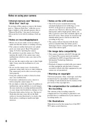
...videotapes, and other bright light. The heat of your camera or recording media, etc. [ On illustrations Illustrations used in any way. • The camera will not function with the lens portion extended when the battery pack is manufactured using the camera (page 31). • Do not shake or ...strike the camera. Insert a charged battery pack, then turn off the camera or remove the battery pack or "Memory ...
...videotapes, and other bright light. The heat of your camera or recording media, etc. [ On illustrations Illustrations used in any way. • The camera will not function with the lens portion extended when the battery pack is manufactured using the camera (page 31). • Do not shake or ...strike the camera. Insert a charged battery pack, then turn off the camera or remove the battery pack or "Memory ...
Instruction Manual
Page 11
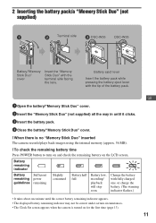
... displayed battery remaining indicator may not be correct under certain circumstances. • The Clock Set screen appears when the camera is no "Memory Stick Duo" inserted The camera records/plays back images using the internal memory (approx. 56 MB). [ To check the remaining battery time Press ...Insert the battery pack while pressing the battery eject lever with the terminal side facing the lens. 2 Inserting the battery pack/a "Memory Stick Duo" (not supplied) ɟ Terminal side ɠ DSC-W55 DSC-W35 Battery/"Memory Stick Duo" cover Insert the "Memory Stick Duo" with the tip of...
... displayed battery remaining indicator may not be correct under certain circumstances. • The Clock Set screen appears when the camera is no "Memory Stick Duo" inserted The camera records/plays back images using the internal memory (approx. 56 MB). [ To check the remaining battery time Press ...Insert the battery pack while pressing the battery eject lever with the terminal side facing the lens. 2 Inserting the battery pack/a "Memory Stick Duo" (not supplied) ɟ Terminal side ɠ DSC-W55 DSC-W35 Battery/"Memory Stick Duo" cover Insert the "Memory Stick Duo" with the tip of...
Instruction Manual
Page 31
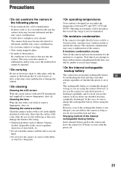
... battery pack in the back pocket of your hand. • Do not leave the camera in extremely cold or hot places that if you attempt to shoot with the power off. 31 Cleaning the lens Wipe the lens with a dry cloth. This moisture condensation may cause a malfunction of whether the power... cold to a warm location, moisture may condense inside the lens, you will be sure to charge this rechargeable battery is not charged, you can still use the camera as long as you are using the camera. Precautions [ Do not use/store the camera in the following as they may damage the finish or...
... battery pack in the back pocket of your hand. • Do not leave the camera in extremely cold or hot places that if you attempt to shoot with the power off. 31 Cleaning the lens Wipe the lens with a dry cloth. This moisture condensation may cause a malfunction of whether the power... cold to a warm location, moisture may condense inside the lens, you will be sure to charge this rechargeable battery is not charged, you can still use the camera as long as you are using the camera. Precautions [ Do not use/store the camera in the following as they may damage the finish or...

Instruction Manual
Page 32
...color CCD, Primary color filter Total pixel number of camera: Approx. 7 410 000 pixels Effective pixel number of camera: Approx. 7 201 000 pixels Lens: Carl Zeiss Vario-Tessar 3× zoom lens f = 6.3 - 18.9 mm (38 - 114 mm when converted to a 35 mm still camera) F2.8 - 5.2 Exposure control: Automatic exposure, Scene... pack NP-BG1, 3.6 V AC-LS5K AC Adaptor (not supplied), 4.2 V Power consumption (during shooting with the LCD screen on): DSC-W55 1.0 W DSC-W35 1.0 W Operating temperature: 0 to 40°C (32 to 104°F) 32 Storage temperature: -20 to +60°C (-4 to +140°F) Dimensions...
...color CCD, Primary color filter Total pixel number of camera: Approx. 7 410 000 pixels Effective pixel number of camera: Approx. 7 201 000 pixels Lens: Carl Zeiss Vario-Tessar 3× zoom lens f = 6.3 - 18.9 mm (38 - 114 mm when converted to a 35 mm still camera) F2.8 - 5.2 Exposure control: Automatic exposure, Scene... pack NP-BG1, 3.6 V AC-LS5K AC Adaptor (not supplied), 4.2 V Power consumption (during shooting with the LCD screen on): DSC-W55 1.0 W DSC-W35 1.0 W Operating temperature: 0 to 40°C (32 to 104°F) 32 Storage temperature: -20 to +60°C (-4 to +140°F) Dimensions...

Service Manual
Page 2
DSC-W55_L2 - 2 - SPECIFICATIONS Camera [System] Image device: 7.20 mm (1/2.5 type) color CCD, Primary color filter Total pixel number of camera: Approx. 7 410 000 pixels Effective pixel number of camera: Approx. 7 201 000 pixels Lens: Carl Zeiss Vario-Tessar 3× zoom lens f = 6.3 - 18.9 mm (38 - 114 mm when converted to a 35 mm still camera) F2.8 -5.2 Exposure control: Automatic exposure...
DSC-W55_L2 - 2 - SPECIFICATIONS Camera [System] Image device: 7.20 mm (1/2.5 type) color CCD, Primary color filter Total pixel number of camera: Approx. 7 410 000 pixels Effective pixel number of camera: Approx. 7 201 000 pixels Lens: Carl Zeiss Vario-Tessar 3× zoom lens f = 6.3 - 18.9 mm (38 - 114 mm when converted to a 35 mm still camera) F2.8 -5.2 Exposure control: Automatic exposure...
Service Manual
Page 5
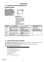
...in the internal memory are reset to be initialized by high voltage, setting of lens drive circuit. 1. Display Code Countermeasure Cause C:32:ss Turn the power off ...SELF-DIAGNOSIS DISPLAY Self-diagnosis display • C: ss: ss You can be deactivated. DSC-W55_L2 1-1 The message "Initialize all settings Ready?" appears. 2 Select [OK] with ...camera malfunction yourself. (However, contact your Sony dealer or local authorized Sony service facility when you cannot recover from the camera malfunction.) • E: ss: ss Contact your Sony dealer or local authorized Sony...
...in the internal memory are reset to be initialized by high voltage, setting of lens drive circuit. 1. Display Code Countermeasure Cause C:32:ss Turn the power off ...SELF-DIAGNOSIS DISPLAY Self-diagnosis display • C: ss: ss You can be deactivated. DSC-W55_L2 1-1 The message "Initialize all settings Ready?" appears. 2 Select [OK] with ...camera malfunction yourself. (However, contact your Sony dealer or local authorized Sony service facility when you cannot recover from the camera malfunction.) • E: ss: ss Contact your Sony dealer or local authorized Sony...

Service Manual
Page 11
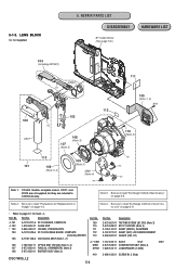
Exchange Method of Barrier Assembly" (2-6 page). Note 2:When you exchange barrier assy and ornamental ring (A), be sure to follow the procedure carried on "2-2. Exchange Method of Zoom Motor Unit" (2-9 page). DSC-W55_L2 2-4 LENS BLOCK EXPLODED VIEW HARDWARE LIST 1-3 1-5 1-1 ST-134 ST-133 1-4 1-6 (Claw) 1-7 2-2 1-2 (Claw) HELP 2-1 2-4 (#19) CD-604 2-5 1 ST-133 Board 2-3 2 Lens Unit Note 1:When you exchange zoom motor unit, be sure to follow the procedure carried on "2-3. 2-1-3.
Exchange Method of Barrier Assembly" (2-6 page). Note 2:When you exchange barrier assy and ornamental ring (A), be sure to follow the procedure carried on "2-2. Exchange Method of Zoom Motor Unit" (2-9 page). DSC-W55_L2 2-4 LENS BLOCK EXPLODED VIEW HARDWARE LIST 1-3 1-5 1-1 ST-134 ST-133 1-4 1-6 (Claw) 1-7 2-2 1-2 (Claw) HELP 2-1 2-4 (#19) CD-604 2-5 1 ST-133 Board 2-3 2 Lens Unit Note 1:When you exchange zoom motor unit, be sure to follow the procedure carried on "2-3. 2-1-3.

Service Manual
Page 14
... removing the Barrier Assy, if the "G1 Dust-Proof Ring" was removed, it must be returned to the lens direction. INSTALL NEW BARRIER ASSY 1 Install new Barrier Assy. 2 Tighten two screws. * Tightening torque = 0.5 kgf 1 2 2 DSC-W55_L2 2-7 In returning the ring, adjust the location of a projection to the home position. This is an...
... removing the Barrier Assy, if the "G1 Dust-Proof Ring" was removed, it must be returned to the lens direction. INSTALL NEW BARRIER ASSY 1 Install new Barrier Assy. 2 Tighten two screws. * Tightening torque = 0.5 kgf 1 2 2 DSC-W55_L2 2-7 In returning the ring, adjust the location of a projection to the home position. This is an...

Service Manual
Page 16
... Board. * Discard the removed Zoom Motor Unit. 1 2 2 3 1 3 3 1 2-3-2. INSTALL NEW ZOOM MOTOR UNIT 1 Install the Lens Flexible Board in new Zoom Motor Unit. 2 Install new Zoom Motor Unit in the Lens Block. 3 Tighten two screws. * Tightening torque = 0.7 kgf 2 1 1 1 DSC-W55_L2 2-9E 3 3 EXCHANGE METHOD OF ZOOM MOTOR UNIT Service parts Part Number 1 2-673-648-01...
... Board. * Discard the removed Zoom Motor Unit. 1 2 2 3 1 3 3 1 2-3-2. INSTALL NEW ZOOM MOTOR UNIT 1 Install the Lens Flexible Board in new Zoom Motor Unit. 2 Install new Zoom Motor Unit in the Lens Block. 3 Tighten two screws. * Tightening torque = 0.7 kgf 2 1 1 1 DSC-W55_L2 2-9E 3 3 EXCHANGE METHOD OF ZOOM MOTOR UNIT Service parts Part Number 1 2-673-648-01...
Service Manual
Page 21
... LCD_CK XCS_ PANEL 36 XIC101_RST_OUT 37 IC101_1_SO, XIC101_1_SCK 11, 12, 13 4 - 10 LCD901 PANEL UNIT 2.5 INCH DIGITAL LCD MONITOR 34, 35 IC101_1_SO, XIC101_1_SCK CN705 (1/2) 23 BL_H CN003(1/2) (LND002) 1 BL_L 21 2 (LND001)... AND (4/6) M7 N7 XAF_LED SP+, SPMIC_SIG 2 OVERALL (2/2) (PAGE 3-2) 3 OVERALL (2/2) (PAGE 3-2) DSC-W55_L2 3-1 CA_AD13 B8, D9, E9 IC301 A2 K6, K5, J6, J5 CCD SIGNAL PROCESS, A3...G6, G5, H5, H4, G4, F4, E4, D7, H7, D4 A4 CLKTGO CAMERA DSP, CPU, E1 LENS CONTROL, F2 MODE CONTROL (2/6) D5 C2 XCS_FE U22 D6 C4 IC101_1_SO, XIC101_1_SCK B3, ...
... LCD_CK XCS_ PANEL 36 XIC101_RST_OUT 37 IC101_1_SO, XIC101_1_SCK 11, 12, 13 4 - 10 LCD901 PANEL UNIT 2.5 INCH DIGITAL LCD MONITOR 34, 35 IC101_1_SO, XIC101_1_SCK CN705 (1/2) 23 BL_H CN003(1/2) (LND002) 1 BL_L 21 2 (LND001)... AND (4/6) M7 N7 XAF_LED SP+, SPMIC_SIG 2 OVERALL (2/2) (PAGE 3-2) 3 OVERALL (2/2) (PAGE 3-2) DSC-W55_L2 3-1 CA_AD13 B8, D9, E9 IC301 A2 K6, K5, J6, J5 CCD SIGNAL PROCESS, A3...G6, G5, H5, H4, G4, F4, E4, D7, H7, D4 A4 CLKTGO CAMERA DSP, CPU, E1 LENS CONTROL, F2 MODE CONTROL (2/6) D5 C2 XCS_FE U22 D6 C4 IC101_1_SO, XIC101_1_SCK B3, ...
Service Manual
Page 23
...BL_L L003 IC601 2.9V REG (5/6) 4 VIN VOUT 3 A_3.2V D_1.8V IC101 CAMERA DSP, CPU, LENS CONTROL, MODE CONTROL, FRONT CONTROL (2/6) LDO3IN B2 LDO3 A2 L002 LX2 C10 CAM_2.9V... (LND001) RL-074 FLEXIBLE SW-498 BOARD BOARD (2/2) (2/2) 2.5 INCH DIGITAL LCD MONITOR LCD BACKLIGHT AU_3.0V M_5V IC603 AUDIO AMP (5/6) FLASH UNIT IC401 LENS DRIVE, MOTOR DRIVER (3/6) CAM_- 7.5V CAM_12V IC202 256M SDRAM, 64M SUPER... FB301 CN301 12 36 CAM_12V CAM_- 7.5V IC002 CCD IMAGER IC001 BUFFER FB107 D_3.2V 08 DSC-W55_L2 3-3E Ver. 1.2 2007.06 3-3. MC-181 FLEXIBLE BOARD ACV_UNREG SY-176 BOARD CN702...
...BL_L L003 IC601 2.9V REG (5/6) 4 VIN VOUT 3 A_3.2V D_1.8V IC101 CAMERA DSP, CPU, LENS CONTROL, MODE CONTROL, FRONT CONTROL (2/6) LDO3IN B2 LDO3 A2 L002 LX2 C10 CAM_2.9V... (LND001) RL-074 FLEXIBLE SW-498 BOARD BOARD (2/2) (2/2) 2.5 INCH DIGITAL LCD MONITOR LCD BACKLIGHT AU_3.0V M_5V IC603 AUDIO AMP (5/6) FLASH UNIT IC401 LENS DRIVE, MOTOR DRIVER (3/6) CAM_- 7.5V CAM_12V IC202 256M SDRAM, 64M SUPER... FB301 CN301 12 36 CAM_12V CAM_- 7.5V IC002 CCD IMAGER IC001 BUFFER FB107 D_3.2V 08 DSC-W55_L2 3-3E Ver. 1.2 2007.06 3-3. MC-181 FLEXIBLE BOARD ACV_UNREG SY-176 BOARD CN702...

Service Manual
Page 24
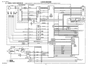
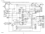
FRAME SCHEMATIC DIAGRAM 4. PRINTED WIRING BOARDS AND SCHEMATIC DIAGRAMS BH001 BATTERY TERMINAL 1 3 LCD901 2.5 INCH DIGITAL LCD MONITOR 29 1 CN702 39 1 28 2 CN901 38 2 LEVEL3 SY-176 BOARD (SIDE A) LEVEL3 SY... 11 12 IC202 (Not supplied) 2 1 31 1 39 CD-604 FLEXIBLE BOARD 39 IC001 (Not supplied) 1 IC002 (Not supplied) LENS BLOCK MC-181 FLEXIBLE BOARD 1 29 26 2 25 28 1 27 CN001 (MULTI CONNECTOR) 23 1 MIC901 MICROPHONE ST-134 FLEXIBLE BOARD...CN003 14 1 SW-498 BOARD (SIDE B) SW-498 BOARD (SIDE A) D901 LCD BACKLIGHT SP901 SPEAKER DSC-W55_L2 4-1 FRAME 4-1.
FRAME SCHEMATIC DIAGRAM 4. PRINTED WIRING BOARDS AND SCHEMATIC DIAGRAMS BH001 BATTERY TERMINAL 1 3 LCD901 2.5 INCH DIGITAL LCD MONITOR 29 1 CN702 39 1 28 2 CN901 38 2 LEVEL3 SY-176 BOARD (SIDE A) LEVEL3 SY... 11 12 IC202 (Not supplied) 2 1 31 1 39 CD-604 FLEXIBLE BOARD 39 IC001 (Not supplied) 1 IC002 (Not supplied) LENS BLOCK MC-181 FLEXIBLE BOARD 1 29 26 2 25 28 1 27 CN001 (MULTI CONNECTOR) 23 1 MIC901 MICROPHONE ST-134 FLEXIBLE BOARD...CN003 14 1 SW-498 BOARD (SIDE B) SW-498 BOARD (SIDE A) D901 LCD BACKLIGHT SP901 SPEAKER DSC-W55_L2 4-1 FRAME 4-1.
Service Manual
Page 26
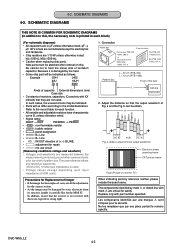
.... • As the imager may be indicated. • Parts with XX indicate that the output waveform of the lens L Camera 2. a (Video output terminal output waveform) Electronic beam scanning frame CRT picture frame Fig.b (Picture on monitor TV) When indicating ... • A: not use circuit (Measuring conditions voltage and waveform) • Voltages and waveforms are measured between the measurement points and ground when camera shoots color bar chart of pattern box.They are in µF unless otherwise noted. b can be damaged by reference number, please include the board...
.... • As the imager may be indicated. • Parts with XX indicate that the output waveform of the lens L Camera 2. a (Video output terminal output waveform) Electronic beam scanning frame CRT picture frame Fig.b (Picture on monitor TV) When indicating ... • A: not use circuit (Measuring conditions voltage and waveform) • Voltages and waveforms are measured between the measurement points and ground when camera shoots color bar chart of pattern box.They are in µF unless otherwise noted. b can be damaged by reference number, please include the board...

Service Manual
Page 27
... supplied, but they are included in CCD block assy. 1 2 3 4 5 6 7 8 CD-604 FLEXIBLE BOARD A CCD IMAGER XX MARK:NO MOUNT B C D SY-176 (1/6) E CN301 PAGE 4-6 of the lens. IC002 CCD IMAGER IC002 ICX629EQP-13 N.C. 4 V2 3 VST 2 V1 1 H2A 32 H1A 31 VL 30 N.C. 29 CL005 H1B H2B RSS3 GND WGND SUB CSUB N.C. 21... 22 23 24 25 26 27 28 R007 XX C005 XX C007 0.1u C006 0.1u DSC-W55_L2 4-5 CD-604 R001 4.7 IC001 BUFFER IC001 CXA3691EN-T9 OUT GND IN 321 456 IDRV VCC ISF C008 0.01u R009 100k R008 0.01u R002 0 ...
... supplied, but they are included in CCD block assy. 1 2 3 4 5 6 7 8 CD-604 FLEXIBLE BOARD A CCD IMAGER XX MARK:NO MOUNT B C D SY-176 (1/6) E CN301 PAGE 4-6 of the lens. IC002 CCD IMAGER IC002 ICX629EQP-13 N.C. 4 V2 3 VST 2 V1 1 H2A 32 H1A 31 VL 30 N.C. 29 CL005 H1B H2B RSS3 GND WGND SUB CSUB N.C. 21... 22 23 24 25 26 27 28 R007 XX C005 XX C007 0.1u C006 0.1u DSC-W55_L2 4-5 CD-604 R001 4.7 IC001 BUFFER IC001 CXA3691EN-T9 OUT GND IN 321 456 IDRV VCC ISF C008 0.01u R009 100k R008 0.01u R002 0 ...

Service Manual
Page 41
REPAIR PARTS LIST NOTE: Characters A to Z of the electrical parts list indicate location of exploded views in which the desired part is shown. Link EXPLODED VIEWS A CABINET BLOCK B LCD BLOCK C LENS BLOCK D BT HOLDER BLOCK Link ELECTRICAL PARTS LIST ACCESSORIES CD-604 FLEXIBLE BOARD C MC-181 FLEXIBLE BOARD D RL-074 FLEXIBLE BOARD B ST-133 BOARD C ST-134 FLEXIBLE BOARD C SW-498 BOARD B DSC-W55_L2 NOTE 5.
REPAIR PARTS LIST NOTE: Characters A to Z of the electrical parts list indicate location of exploded views in which the desired part is shown. Link EXPLODED VIEWS A CABINET BLOCK B LCD BLOCK C LENS BLOCK D BT HOLDER BLOCK Link ELECTRICAL PARTS LIST ACCESSORIES CD-604 FLEXIBLE BOARD C MC-181 FLEXIBLE BOARD D RL-074 FLEXIBLE BOARD B ST-133 BOARD C ST-134 FLEXIBLE BOARD C SW-498 BOARD B DSC-W55_L2 NOTE 5.

Service Manual
Page 44
REPAIR PARTS LIST DISASSEMBLY HARDWARE LIST #5 53 (including RL-074 flexible board) LCD901 54 51 52 BT001 SW-498 ns 57 55 58 Lens Block ! : BT001 (LITHIUM RECHARGEABLE BATTERY) Board on the mount position. (See page 5-4.) (See page 4-20.) CAUTION Danger of explosion if battery is incorrectly replaced. Description A-... (240), MOARE 3-941-343-21 TAPE (A) 0 BT001 1-756-711-11 LITHIUM RECHARGEABLE BATTERY LCD901 8-753-282-44 ACX358AKQ-3 #5 3-080-204-01 SCREW, TAPPING, P2 (Black) DSC-W55_L2 5-3
REPAIR PARTS LIST DISASSEMBLY HARDWARE LIST #5 53 (including RL-074 flexible board) LCD901 54 51 52 BT001 SW-498 ns 57 55 58 Lens Block ! : BT001 (LITHIUM RECHARGEABLE BATTERY) Board on the mount position. (See page 5-4.) (See page 4-20.) CAUTION Danger of explosion if battery is incorrectly replaced. Description A-... (240), MOARE 3-941-343-21 TAPE (A) 0 BT001 1-756-711-11 LITHIUM RECHARGEABLE BATTERY LCD901 8-753-282-44 ACX358AKQ-3 #5 3-080-204-01 SCREW, TAPPING, P2 (Black) DSC-W55_L2 5-3
Service Manual
Page 45
... 1-788-363-11 OPTICS UNIT (ED13A) (Note 3, 4) 0* C901 M901 107 2-673-650-01 RING (A), ORNAMENTAL (Note 3) SP901 108 2-673-652-01 BARRIER ASSY (Note 3) #19 DSC-W55_L2 5-4 Part No. Note 3: Be sure to read "Exchange method of zoom motor unit" on page 2-9. • Refer to page 5-1 for Replacement of barrier assy... 4) ns ns ns ns Note 1: CD-604 flexible complete board, IC001 and IC002 are not supplied, but they are included in CCD block assy. Ref. LENS BLOCK ns: not supplied 5. 5-1-3. Note 4: Be sure to read "Precautions for mark 0.
... 1-788-363-11 OPTICS UNIT (ED13A) (Note 3, 4) 0* C901 M901 107 2-673-650-01 RING (A), ORNAMENTAL (Note 3) SP901 108 2-673-652-01 BARRIER ASSY (Note 3) #19 DSC-W55_L2 5-4 Part No. Note 3: Be sure to read "Exchange method of zoom motor unit" on page 2-9. • Refer to page 5-1 for Replacement of barrier assy... 4) ns ns ns ns Note 1: CD-604 flexible complete board, IC001 and IC002 are not supplied, but they are included in CCD block assy. Ref. LENS BLOCK ns: not supplied 5. 5-1-3. Note 4: Be sure to read "Precautions for mark 0.


