User Guide
Page 58
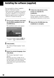
... language, then click [Next]. Installing the software (supplied) You can install the software (supplied) using Windows 2000/Me, do not connect the camera to the computer before installation. • In Windows 2000/XP, log on as Administrator. • When the supplied software is installed, the USB... driver is installed automatically. 1 Turn on the screen. 5 Remove the CD-ROM after the installation is complete. • If it does not appear...
... language, then click [Next]. Installing the software (supplied) You can install the software (supplied) using Windows 2000/Me, do not connect the camera to the computer before installation. • In Windows 2000/XP, log on as Administrator. • When the supplied software is installed, the USB... driver is installed automatically. 1 Turn on the screen. 5 Remove the CD-ROM after the installation is complete. • If it does not appear...
User Guide
Page 86
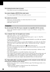
... cut. The "System Properties" screen appears. 86 Computers You do not know if the OS of your computer. • Connect the camera directly to install the USB driver again. Make sure that "USB Mode Mass Storage" is displayed (page 60). • Set [USB Connect] to [Mass Storage] ...; When the battery level is for multi-use terminal (DSC-W50/W70) or the USB cable (DSC-W30/W40) before you installed the software (supplied). You cannot cut (shorter than the camera, the keyboard and the mouse from your computer with the camera. • Check "Recommended computer environment" on page 57...
... cut. The "System Properties" screen appears. 86 Computers You do not know if the OS of your computer. • Connect the camera directly to install the USB driver again. Make sure that "USB Mode Mass Storage" is displayed (page 60). • Set [USB Connect] to [Mass Storage] ...; When the battery level is for multi-use terminal (DSC-W50/W70) or the USB cable (DSC-W30/W40) before you installed the software (supplied). You cannot cut (shorter than the camera, the keyboard and the mouse from your computer with the camera. • Check "Recommended computer environment" on page 57...

Service Manual
Page 14
...ring be peeled while heating the portions 1 → 2 in the under figure one by one sequentially. * Discard the removed Ornamental Ring A. 1 2 Tip DSC-W30/W40_L2 2-6 EXCHANGE METHOD OF BARRIER ASSY Service parts Part Number 1 2-673-650-01 2 2-673-652-01 3 2-673-651-01 Part Name Ring (A), ...Ornamental Barrier Assy Tapping screw (B1.2×4) Quantity 1 1 2 Tools used Torque driver Soldering iron Weight about 300ºC. In case of the group-1 frame. PEEL OFF OLD ORNAMENTAL RING A The Ornamental Ring A has adhered to the Barrier...
...ring be peeled while heating the portions 1 → 2 in the under figure one by one sequentially. * Discard the removed Ornamental Ring A. 1 2 Tip DSC-W30/W40_L2 2-6 EXCHANGE METHOD OF BARRIER ASSY Service parts Part Number 1 2-673-650-01 2 2-673-652-01 3 2-673-651-01 Part Name Ring (A), ...Ornamental Barrier Assy Tapping screw (B1.2×4) Quantity 1 1 2 Tools used Torque driver Soldering iron Weight about 300ºC. In case of the group-1 frame. PEEL OFF OLD ORNAMENTAL RING A The Ornamental Ring A has adhered to the Barrier...

Service Manual
Page 17
... Motor Unit BT2 P1.4×3 B3C Quantity 1 2 Tools used Torque driver 1 2 2-3-1. 2-3. INSTALL NEW ZOOM MOTOR UNIT 1 Install the Lens Flexible Board in new Zoom Motor Unit. 2 Install new Zoom Motor Unit in the Lens Block. 3 Tighten two screws. * Tightening torque = 0.7 kgf 2 1 1 1 DSC-W30/W40_L2 2-9E 3 3 REMOVE OLD ZOOM MOTOR UNIT 1 Remove two screws...
... Motor Unit BT2 P1.4×3 B3C Quantity 1 2 Tools used Torque driver 1 2 2-3-1. 2-3. INSTALL NEW ZOOM MOTOR UNIT 1 Install the Lens Flexible Board in new Zoom Motor Unit. 2 Install new Zoom Motor Unit in the Lens Block. 3 Tighten two screws. * Tightening torque = 0.7 kgf 2 1 1 1 DSC-W30/W40_L2 2-9E 3 3 REMOVE OLD ZOOM MOTOR UNIT 1 Remove two screws...


