Instruction Manual
Page 2
...[ Power Sources This set should still fail to fit, contact your Sony dealer regarding this product. For Customers in the space provided below. This... moisture. Record the serial number in the U.S.A. Refer to have a suitable outlet installed. Model No. DSC-S650/S700 Serial No WARNING To reduce fire or shock hazard, do not expose the unit to insert the plug fully... one way. This plug will fit into the set may touch dangerous voltage points or short out parts that may cause hazards. If you call upon your electrician to these safety instructions completely before operating the...
...[ Power Sources This set should still fail to fit, contact your Sony dealer regarding this product. For Customers in the space provided below. This... moisture. Record the serial number in the U.S.A. Refer to have a suitable outlet installed. Model No. DSC-S650/S700 Serial No WARNING To reduce fire or shock hazard, do not expose the unit to insert the plug fully... one way. This plug will fit into the set may touch dangerous voltage points or short out parts that may cause hazards. If you call upon your electrician to these safety instructions completely before operating the...
Instruction Manual
Page 3
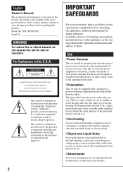
... Do not place the set near a bathtub, washbowl, kitchen sink, or laundry tub, in a confined space, such as the original parts. If the set does not operate normally when following conditions: - Never block the slots and openings by the manufacturer. [ Ventilation The slots.... Service [ Damage Requiring Service Unplug the set from the wall outlet and refer servicing to qualified service personnel. [ Replacement parts When replacement parts are provided for cleaning the exterior of time, unplug it from overheating, these slots and openings must never be blocked or covered...
... Do not place the set near a bathtub, washbowl, kitchen sink, or laundry tub, in a confined space, such as the original parts. If the set does not operate normally when following conditions: - Never block the slots and openings by the manufacturer. [ Ventilation The slots.... Service [ Damage Requiring Service Unplug the set from the wall outlet and refer servicing to qualified service personnel. [ Replacement parts When replacement parts are provided for cleaning the exterior of time, unplug it from overheating, these slots and openings must never be blocked or covered...
Instruction Manual
Page 4
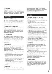
... Material : Lithium battery contains perchlorate 4 These limits are cautioned that interference will not occur in accordance with the limits for a digital device pursuant to radio communications. The supplied interface cable must be determined by one or more of the following two conditions: (1) ... that any changes or modifications not expressly approved in order to comply with the instructions, may cause harmful interference to Subpart B of Part 15 of the FCC Rules. Connect the equipment into an outlet on , the user is connected. - special handling may cause undesired...
... Material : Lithium battery contains perchlorate 4 These limits are cautioned that interference will not occur in accordance with the limits for a digital device pursuant to radio communications. The supplied interface cable must be determined by one or more of the following two conditions: (1) ... that any changes or modifications not expressly approved in order to comply with the instructions, may cause harmful interference to Subpart B of Part 15 of the FCC Rules. Connect the equipment into an outlet on , the user is connected. - special handling may cause undesired...
Service Manual
Page 1
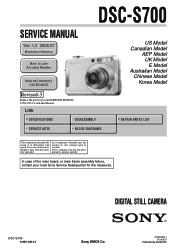
... Internal memory ON BOARD Revised-3 Replace the previously issued SERVICE MANUAL 9-852-183-13 with part number specified. Les composants identifiés par une marque 0 sont critiques pour la sécurité. DIGITAL STILL CAMERA DSC-S700 9-852-183-14 Sony EMCS Co. 2008G0800-1 © 2008.07 Published by mark 0 or dotted line with mark 0 are...
... Internal memory ON BOARD Revised-3 Replace the previously issued SERVICE MANUAL 9-852-183-13 with part number specified. Les composants identifiés par une marque 0 sont critiques pour la sécurité. DIGITAL STILL CAMERA DSC-S700 9-852-183-14 Sony EMCS Co. 2008G0800-1 © 2008.07 Published by mark 0 or dotted line with mark 0 are...
Service Manual
Page 3
REPLACE THESE COMPONENTS WITH SONY PARTS WHOSE PART NUMBERS APPEAR AS SHOWN IN THIS MANUAL OR IN SUPPLEMENTS PUBLISHED BY SONY. Check the entire board surface for unsoldered or poorly-soldered connections. Point them out to the customer and recommend their particular size... Unleaded solder Boards requiring use of the soldering iron around 270°C during a previous repair. Caution: The printed pattern (copper foil) may DSC-S700 also be careful! • Strong viscosity circuit board (within 3 times). ordinary solder so use only unleaded solder but the iron tip has ...
REPLACE THESE COMPONENTS WITH SONY PARTS WHOSE PART NUMBERS APPEAR AS SHOWN IN THIS MANUAL OR IN SUPPLEMENTS PUBLISHED BY SONY. Check the entire board surface for unsoldered or poorly-soldered connections. Point them out to the customer and recommend their particular size... Unleaded solder Boards requiring use of the soldering iron around 270°C during a previous repair. Caution: The printed pattern (copper foil) may DSC-S700 also be careful! • Strong viscosity circuit board (within 3 times). ordinary solder so use only unleaded solder but the iron tip has ...

Service Manual
Page 4
Ver. 1.2 2008.06 The changed portions from Ver. 1.1 are shown in Internal Memory 1-1 2. Process After Fixing Flash Error 1-1 1-2. Lens Block 4-3 4-2. Method for Copying or Erasing the Data in blue. Power Block Diagram 3-2 4. Overall Section 4-1 4-1-2. Main Frame Block 4-2 4-1-3. Disassembly 2-1 3. REPAIR PARTS LIST 4-1. Overall Block Diagram 3-1 3-2. SERVICE NOTE 1-1. Exploded Views 4-1 4-1-1. Accessories 4-4 DSC-S700 - 4 - TABLE OF CONTENTS Section Title Page 1. BLOCK DIAGRAMS 3-1. DISASSEMBLY 2-1.
Ver. 1.2 2008.06 The changed portions from Ver. 1.1 are shown in Internal Memory 1-1 2. Process After Fixing Flash Error 1-1 1-2. Lens Block 4-3 4-2. Method for Copying or Erasing the Data in blue. Power Block Diagram 3-2 4. Overall Section 4-1 4-1-2. Main Frame Block 4-2 4-1-3. Disassembly 2-1 3. REPAIR PARTS LIST 4-1. Overall Block Diagram 3-1 3-2. SERVICE NOTE 1-1. Exploded Views 4-1 4-1-1. Accessories 4-4 DSC-S700 - 4 - TABLE OF CONTENTS Section Title Page 1. BLOCK DIAGRAMS 3-1. DISASSEMBLY 2-1.
Service Manual
Page 10
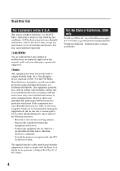
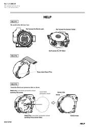
HELP03 Attach the Block assy protection sheet as shown. HELP HELP01 Be careful about the Lens Assy. Don't press the Barrier part. Lens block protection sheet Screw hole Screw DSC-S700 Attach the Lens block protection sheet avoiding three screw holes. Screw holes HELP Don't press the Sensor holder HELP02 Don't press the AF Motor Keep clean these Pins. Ver. 1.3 2008.07 The changed portions from Ver. 1.2 are shown in blue. Attach the Lens block protection sheet covering this screw.
HELP03 Attach the Block assy protection sheet as shown. HELP HELP01 Be careful about the Lens Assy. Don't press the Barrier part. Lens block protection sheet Screw hole Screw DSC-S700 Attach the Lens block protection sheet avoiding three screw holes. Screw holes HELP Don't press the Sensor holder HELP02 Don't press the AF Motor Keep clean these Pins. Ver. 1.3 2008.07 The changed portions from Ver. 1.2 are shown in blue. Attach the Lens block protection sheet covering this screw.
Service Manual
Page 13
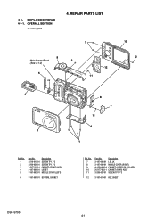
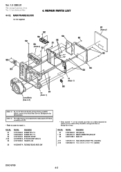
...6 3-197-601-01 BOTTOM, CABINET Ref. No. 7 8 9 10 11 Part No. REPAIR PARTS LIST 2 10 9 Main Frame Block 2 (See 4-1-2) 2 12 5 11 ns 4 3 8 7 11 6 1 Ref. OVERALL SECTION ns: not supplied 4. No. 1 2 3 4 5 Part No. 4-1. Description 3-197-605-01 LID, JK 3-197-602-01 MIDDLE COVER ...(RIGHT) A-1254-905-A CABINET (UPPER) BLOCK ASSY X-2177-833-1 CABINET (REAR) ASSY 3-209-037-01 SCREW TP1.7*3 12 3-197-610-01 KEY, SHEET DSC-S700 4-1
...6 3-197-601-01 BOTTOM, CABINET Ref. No. 7 8 9 10 11 Part No. REPAIR PARTS LIST 2 10 9 Main Frame Block 2 (See 4-1-2) 2 12 5 11 ns 4 3 8 7 11 6 1 Ref. OVERALL SECTION ns: not supplied 4. No. 1 2 3 4 5 Part No. 4-1. Description 3-197-605-01 LID, JK 3-197-602-01 MIDDLE COVER ...(RIGHT) A-1254-905-A CABINET (UPPER) BLOCK ASSY X-2177-833-1 CABINET (REAR) ASSY 3-209-037-01 SCREW TP1.7*3 12 3-197-610-01 KEY, SHEET DSC-S700 4-1
Service Manual
Page 14
Some delay should be anticipated when or dering these items. Ref. REPAIR PARTS LIST 52 53 52 59 56 52 52 54 52 51 (Note 2) 52 ...57 (Note 2) 52 (Note 1) In case of the main board, or main frame assembly failure, contact your local Sony Service Headquarter for the measures. (Note 2) The adjustment is not required after replacing the ST block assembly or LCD. &#...-11 FUSE, MICRO (1608 TYPE) (1.6A/36V) 1-576-363-11 FUSE, MICRO (1005 TYPE) (1A/30V) DSC-S700 4-2 No. 57 * 58 59 Part No. Description 3-113-002-01 SCREW TP1.4*3 3-209-036-01 SCREW TP1.7*3 3-197-607-01 BRACKET, STRAP A-1249...
Some delay should be anticipated when or dering these items. Ref. REPAIR PARTS LIST 52 53 52 59 56 52 52 54 52 51 (Note 2) 52 ...57 (Note 2) 52 (Note 1) In case of the main board, or main frame assembly failure, contact your local Sony Service Headquarter for the measures. (Note 2) The adjustment is not required after replacing the ST block assembly or LCD. &#...-11 FUSE, MICRO (1608 TYPE) (1.6A/36V) 1-576-363-11 FUSE, MICRO (1005 TYPE) (1A/30V) DSC-S700 4-2 No. 57 * 58 59 Part No. Description 3-113-002-01 SCREW TP1.4*3 3-209-036-01 SCREW TP1.7*3 3-197-607-01 BRACKET, STRAP A-1249...
Service Manual
Page 15
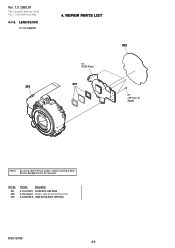
REPAIR PARTS LIST ns (CCD Assy) 301 302 ns (TP1.4 × 3) (Note) (Note) In case of the CCD Assy failure, contact your local Sony Service Headquarter for the measures. Ref. No. 301 302 303 Part No. Description 4-110-079-01 FILTER SET, LOW PASS 4-110-076-01 SHEET, LENS BLOCK PROTECTION A-1253-626-A LENS BLOCK ASSY (SERVICE) DSC-S700 4-3 LENS BLOCK ns: not supplied 303 4. Ver. 1.3 2008.07 The changed portions from Ver. 1.2 are shown in blue. 4-1-3.
REPAIR PARTS LIST ns (CCD Assy) 301 302 ns (TP1.4 × 3) (Note) (Note) In case of the CCD Assy failure, contact your local Sony Service Headquarter for the measures. Ref. No. 301 302 303 Part No. Description 4-110-079-01 FILTER SET, LOW PASS 4-110-076-01 SHEET, LENS BLOCK PROTECTION A-1253-626-A LENS BLOCK ASSY (SERVICE) DSC-S700 4-3 LENS BLOCK ns: not supplied 303 4. Ver. 1.3 2008.07 The changed portions from Ver. 1.2 are shown in blue. 4-1-3.
Service Manual
Page 16
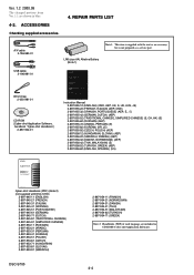
REPAIR PARTS LIST A/V cable 3-196-980-01 USB cable 3-196-981-01 Wrist strap 2-050-981-01 CD-ROM (Cyber-shot Application Software, handbook "Cyber-shot Handbook") 2-897-942-01 Note 1: This item is not prepared as an accessory, but is supplied with DSC-S700) 2-897-945-11 (ENGLISH) 2-897-..."Instruction Manual" thoroughly, and retain it for future reference. © 2007 Sony Corporation CLICK! LR6 (size AA) Alkaline Battery (Note 1) GB DSC-S650 For details on the advanced operations, please access "Cyber-shot Handbook" contained on the bottom. Record the serial number in blue. 4-2....
REPAIR PARTS LIST A/V cable 3-196-980-01 USB cable 3-196-981-01 Wrist strap 2-050-981-01 CD-ROM (Cyber-shot Application Software, handbook "Cyber-shot Handbook") 2-897-942-01 Note 1: This item is not prepared as an accessory, but is supplied with DSC-S700) 2-897-945-11 (ENGLISH) 2-897-..."Instruction Manual" thoroughly, and retain it for future reference. © 2007 Sony Corporation CLICK! LR6 (size AA) Alkaline Battery (Note 1) GB DSC-S650 For details on the advanced operations, please access "Cyber-shot Handbook" contained on the bottom. Record the serial number in blue. 4-2....
Service Manual
Page 17
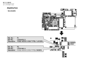
Ver. 1.3 2008.07 The changed portions from Ver. 1.2 are shown in blue. [Regarding Fuse] • MCU BOARD Ref. No. : F2 Part No. : 1-576-363-11 Description : FUSE, MICRO (1005 TYPE) (1A/30V) No. : F1 Part No. : 1-576-913-11 Description : FUSE, MICRO (1068 TYPE) (1.6A/36V) Ref.
Ver. 1.3 2008.07 The changed portions from Ver. 1.2 are shown in blue. [Regarding Fuse] • MCU BOARD Ref. No. : F2 Part No. : 1-576-363-11 Description : FUSE, MICRO (1005 TYPE) (1A/30V) No. : F1 Part No. : 1-576-913-11 Description : FUSE, MICRO (1068 TYPE) (1.6A/36V) Ref.

Service Manual
Page 18
... rotating the screen display "Zoom in/out" • Click the triangle button in the text box.) Application to the Service Manual: The parts on the removal flowchart page or drawing page), and the pointer will go and back between circuit diagram and printed circuit board diagram, and ...button on cover and the table of contents page, or blue characters on the drawing pages (block diagrams, circuit diagrams, printed circuit boards) and parts list pages in a text can move to the link destination. Reversing the screens displayed once • To reverse the previous screens (operation) ...
... rotating the screen display "Zoom in/out" • Click the triangle button in the text box.) Application to the Service Manual: The parts on the removal flowchart page or drawing page), and the pointer will go and back between circuit diagram and printed circuit board diagram, and ...button on cover and the table of contents page, or blue characters on the drawing pages (block diagrams, circuit diagrams, printed circuit boards) and parts list pages in a text can move to the link destination. Reversing the screens displayed once • To reverse the previous screens (operation) ...
Service Manual
Page 19
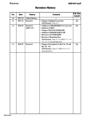
... S.M. issued 1.0 2007.02 Official Release - - 1.1 2007.10 Revised-1 • Change of Regarding Fuse S.M. F2 and Yes Ref. Revised : Page 2-4, HELP, 4-2, 4-3, Regarding Fuse DSC-S700 Revised : Page 4-4 1.2 2008.06 Revised-2 • Addition of DISASSEMBLY for Ref. No. 302 S.M. Revised : Page 4, 2-4, HELP, 3-1, 3-2, 4-2, 4-3, 4-4, Regarding Fuse 1.3 2008...Yes (DI08-133) • Addition of HELP • Change of BLOCK DIAGRAMS • Addition of REPAIR PARTS LIST • Revision of ACCESSORIES • Revision of Supplied accessories Yes S.M. No. Rev.
... S.M. issued 1.0 2007.02 Official Release - - 1.1 2007.10 Revised-1 • Change of Regarding Fuse S.M. F2 and Yes Ref. Revised : Page 2-4, HELP, 4-2, 4-3, Regarding Fuse DSC-S700 Revised : Page 4-4 1.2 2008.06 Revised-2 • Addition of DISASSEMBLY for Ref. No. 302 S.M. Revised : Page 4, 2-4, HELP, 3-1, 3-2, 4-2, 4-3, 4-4, Regarding Fuse 1.3 2008...Yes (DI08-133) • Addition of HELP • Change of BLOCK DIAGRAMS • Addition of REPAIR PARTS LIST • Revision of ACCESSORIES • Revision of Supplied accessories Yes S.M. No. Rev.


