Operating Instructions
Page 1
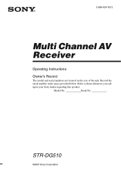
Serial No. Refer to them whenever you call upon your Sony dealer regarding this product. STR-DG510 ©2007 Sony Corporation 2-898-429-11(1) Multi Channel AV Receiver Operating Instructions Owner's Record The model and serial numbers are located on the rear of the unit. Record the serial number in the space provided below. Model No.
Serial No. Refer to them whenever you call upon your Sony dealer regarding this product. STR-DG510 ©2007 Sony Corporation 2-898-429-11(1) Multi Channel AV Receiver Operating Instructions Owner's Record The model and serial numbers are located on the rear of the unit. Record the serial number in the space provided below. Model No.

Operating Instructions
Page 3
... Interface (HDMITM) technology. The recycling of materials will help to the applicable collection point for model STR-DG510. You can also use the controls on the receiver if they have the same or similar names as household waste. In this manual are clearly indicated in...the environment and human health, which could otherwise be caused by looking at the lower right corner of HDMI Licensing LLC. 3GB This receiver incorporates Dolby* Digital and Pro Logic Surround and the DTS** Digital Surround System. * Manufactured under license from Dolby Laboratories. "Dolby", ...
... Interface (HDMITM) technology. The recycling of materials will help to the applicable collection point for model STR-DG510. You can also use the controls on the receiver if they have the same or similar names as household waste. In this manual are clearly indicated in...the environment and human health, which could otherwise be caused by looking at the lower right corner of HDMI Licensing LLC. 3GB This receiver incorporates Dolby* Digital and Pro Logic Surround and the DTS** Digital Surround System. * Manufactured under license from Dolby Laboratories. "Dolby", ...

Service Manual
Page 1
...Models of Dolby Laboratories. MULTI CHANNEL AV RECEIVER 9-887-536-01 2007A04-1 © 2007. 01 Sony Corporation Home Audio Division Published by Sony Techno Create Corporation 1 This receiver incorporates High-Definition Multimedia Interface (HDMITM...) technology. AUDIO POWER SPECIFICATIONS POWER OUTPUT AND TOTAL HARMONIC DISTORTION: (Models of HDMI Licensing LLC. rated 90 watts per channel minimum RMS power, with no sound output. - SERVICE MANUAL Ver. 1.0 2007. 01 STR-DG510...
...Models of Dolby Laboratories. MULTI CHANNEL AV RECEIVER 9-887-536-01 2007A04-1 © 2007. 01 Sony Corporation Home Audio Division Published by Sony Techno Create Corporation 1 This receiver incorporates High-Definition Multimedia Interface (HDMITM...) technology. AUDIO POWER SPECIFICATIONS POWER OUTPUT AND TOTAL HARMONIC DISTORTION: (Models of HDMI Licensing LLC. rated 90 watts per channel minimum RMS power, with no sound output. - SERVICE MANUAL Ver. 1.0 2007. 01 STR-DG510...

Service Manual
Page 2
...) (1) Remote commander RM-AAU013 (1) R6 (size-AA) batteries (2) Optimizer microphone ECM-AC2 (1) Design and specifications are subject to change the tuning scale. STR-DG510 Frequency response Analog Inputs Analog Digital (Coaxial) Digital (Optical) Output (Analog) AUDIO OUT SUB WOOFER Tone Gain levels 10 Hz - 70 kHz +0.5/-2 dB ...step 3) INPUT SHORT (with sound field and tone bypassed). 4) Weighted network, input level. After tuning in any AM station, turn off the receiver. All preset stations will be erased when you change without notice. • Abbreviation CND : Canadian model 2
...) (1) Remote commander RM-AAU013 (1) R6 (size-AA) batteries (2) Optimizer microphone ECM-AC2 (1) Design and specifications are subject to change the tuning scale. STR-DG510 Frequency response Analog Inputs Analog Digital (Coaxial) Digital (Optical) Output (Analog) AUDIO OUT SUB WOOFER Tone Gain levels 10 Hz - 70 kHz +0.5/-2 dB ...step 3) INPUT SHORT (with sound field and tone bypassed). 4) Weighted network, input level. After tuning in any AM station, turn off the receiver. All preset stations will be erased when you change without notice. • Abbreviation CND : Canadian model 2

Service Manual
Page 3
...;S PAR UNE MARQUE 0 SUR LES DIAGRAMMES SCHÉMATIQUES ET LA LISTE DES PIÈCES SONT CRITIQUES POUR LA SÉCURITÉ DE FONCTIONNEMENT. STR-DG510 SAFETY CHECK-OUT (US MODEL) After correcting the original service problem, perform the following safety check before releasing the set to chassis, must have a 2 V AC... MARK 0 ON THE SCHEMATIC DIAGRAMS AND IN THE PARTS LIST ARE CRITICAL TO SAFE OPERATION. NE REMPLACER CES COMPOSANTS QUE PAR DES PIÈCES SONY DONT LES NUMÉROS SONT DONNÉS DANS CE MANUEL OU DANS LES SUPPLÉMENTS PUBLIÉS PAR...
...;S PAR UNE MARQUE 0 SUR LES DIAGRAMMES SCHÉMATIQUES ET LA LISTE DES PIÈCES SONT CRITIQUES POUR LA SÉCURITÉ DE FONCTIONNEMENT. STR-DG510 SAFETY CHECK-OUT (US MODEL) After correcting the original service problem, perform the following safety check before releasing the set to chassis, must have a 2 V AC... MARK 0 ON THE SCHEMATIC DIAGRAMS AND IN THE PARTS LIST ARE CRITICAL TO SAFE OPERATION. NE REMPLACER CES COMPOSANTS QUE PAR DES PIÈCES SONY DONT LES NUMÉROS SONT DONNÉS DANS CE MANUEL OU DANS LES SUPPLÉMENTS PUBLIÉS PAR...

Service Manual
Page 4
... (2/2 24 5-10. Schematic Diagram - Video Section 32 5-18. HDMI SW Section 18 5-5. Printed Wiring Board - DCAC, Power Key Section - .... 35 5-22. Front Panel Section 50 6-3. STR-DG510 TABLE OF CONTENTS 1. GENERAL Description and location of parts 5 2. Back Panel Section 9 2-4. TEST MODE 12 4. Block Diagram - Power Section 20 5-7. Digital Section (2/4 28 5-14. Schematic...
... (2/2 24 5-10. Schematic Diagram - Video Section 32 5-18. HDMI SW Section 18 5-5. Printed Wiring Board - DCAC, Power Key Section - .... 35 5-22. Front Panel Section 50 6-3. STR-DG510 TABLE OF CONTENTS 1. GENERAL Description and location of parts 5 2. Back Panel Section 9 2-4. TEST MODE 12 4. Block Diagram - Power Section 20 5-7. Digital Section (2/4 28 5-14. Schematic...

Service Manual
Page 5
... I Tuner indicators J Preset station indicators K D.RANGE L COAX M Playback channel indicators L R C SL SR S Function Lights up when the receiver applies Pro Logic processing to tune in radio stations you have preset. Press to headphones (page 64). N PHONES jack Connects to activate the Auto Calibration...DVD input is decoding Dolby Digital signals. However, "UNLOCK" appears on the display (page 57, 59). AUTO SW LCR SL SR STR-DG510 This section is set to select the input mode when the same components are connected. C Display The current status of the selected component...
... I Tuner indicators J Preset station indicators K D.RANGE L COAX M Playback channel indicators L R C SL SR S Function Lights up when the receiver applies Pro Logic processing to tune in radio stations you have preset. Press to headphones (page 64). N PHONES jack Connects to activate the Auto Calibration...DVD input is decoding Dolby Digital signals. However, "UNLOCK" appears on the display (page 57, 59). AUTO SW LCR SL SR STR-DG510 This section is set to select the input mode when the same components are connected. C Display The current status of the selected component...

Service Manual
Page 6
...Sony audio/video components that the remote is displayed on a list menu (e.g. exit the menu while the menu or on the TV screen. Press DISPLAY and TV (M) at (on/standby) the same time to display TV's information on the TV screen. erasing multiple titles). STR-DG510... TV ?/1 Press TV ?/1 and TV (M) at the same time to turn off the receiver and other components (SYSTEM STANDBY). You can use V, v, B, b and (P) to ... < / ADVANCE Function Press to display the menu of all components, press ?/1 and AV ?/1 (A) at the same time. AM ANTENNA terminals Connects to turn on or off...
...Sony audio/video components that the remote is displayed on a list menu (e.g. exit the menu while the menu or on the TV screen. Press DISPLAY and TV (M) at (on/standby) the same time to display TV's information on the TV screen. erasing multiple titles). STR-DG510... TV ?/1 Press TV ?/1 and TV (M) at the same time to turn off the receiver and other components (SYSTEM STANDBY). You can use V, v, B, b and (P) to ... < / ADVANCE Function Press to display the menu of all components, press ?/1 and AV ?/1 (A) at the same time. AM ANTENNA terminals Connects to turn on or off...

Service Manual
Page 7
...may not be possible or may operate differently than described. • The VIDEO 3 button on the component, the above explanation is not available for receiver operation. 14GB STR-DG510 7 channel numbers of the CD player, DVD player or blu-ray disc player. U TV INPUT Press TV INPUT and TV (M) at the ... TV (M) at the same time to select the TV channels. V AUTO CAL Press to activate the Sleep Timer function and the duration which the receiver turns off automatically. and TV (M) at the same time to select the channel entry mode, either one or two digits of the TV. >10...
...may not be possible or may operate differently than described. • The VIDEO 3 button on the component, the above explanation is not available for receiver operation. 14GB STR-DG510 7 channel numbers of the CD player, DVD player or blu-ray disc player. U TV INPUT Press TV INPUT and TV (M) at the ... TV (M) at the same time to select the TV channels. V AUTO CAL Press to activate the Sleep Timer function and the duration which the receiver turns off automatically. and TV (M) at the same time to select the channel entry mode, either one or two digits of the TV. >10...

Service Manual
Page 8
BACK PANEL SECTION (Page 9) (Page 9) 2-4. DIGITAL BOARD (Page 10) 2-6. MAIN BOARD SECTION (Page 10) Note : Follow the disassembly procedure in the numerical order given. 2-1. CASE 2 two screws (case 3 TP2) 3 two screws (+BVTP 3 × 8) 4 case 1 two screws (case 3 TP2) 8 CASE (Page 8) 2-2. STR-DG510 SECTION 2 DISASSEMBLY Note : This set can be disassemble according to the following sequence. SET 2-1. STANDBY BOARD (Page 11) 2-5. FRONT PANEL SECTION 2-3.
BACK PANEL SECTION (Page 9) (Page 9) 2-4. DIGITAL BOARD (Page 10) 2-6. MAIN BOARD SECTION (Page 10) Note : Follow the disassembly procedure in the numerical order given. 2-1. CASE 2 two screws (case 3 TP2) 3 two screws (+BVTP 3 × 8) 4 case 1 two screws (case 3 TP2) 8 CASE (Page 8) 2-2. STR-DG510 SECTION 2 DISASSEMBLY Note : This set can be disassemble according to the following sequence. SET 2-1. STANDBY BOARD (Page 11) 2-5. FRONT PANEL SECTION 2-3.

Service Manual
Page 9
...) (CNS507) wire (flat type) (11 core) (AEP, UK) (CNS508) 9 FRONT PANEL SECTION 3 CNP908 (3P) 1 CNP790 (4P) 5 two screws (+BVTP 3 × 8) 4 CNP732 (3P) 7 front panel section 2-3. STR-DG510 2-2.
...) (CNS507) wire (flat type) (11 core) (AEP, UK) (CNS508) 9 FRONT PANEL SECTION 3 CNP908 (3P) 1 CNP790 (4P) 5 two screws (+BVTP 3 × 8) 4 CNP732 (3P) 7 front panel section 2-3. STR-DG510 2-2.

Service Manual
Page 10
STR-DG510 2-4. DIGITAL BOARD 2 CNP503 (8P) 1 CNP505 (7P) 4 DIGITAL board 3 screw (+BVTP 3 × 8) 2-5. MAIN BOARD SECTION 1 CNP906 4 screw (+BV3 (3-CR)) 5 two screws (+BV3 (3-CR)) 2 CNP902 (5P) 3 CNP901 (3P) 6 two screws (+BV3 (3-CR)) 7 MAIN board section 10
STR-DG510 2-4. DIGITAL BOARD 2 CNP503 (8P) 1 CNP505 (7P) 4 DIGITAL board 3 screw (+BVTP 3 × 8) 2-5. MAIN BOARD SECTION 1 CNP906 4 screw (+BV3 (3-CR)) 5 two screws (+BV3 (3-CR)) 2 CNP902 (5P) 3 CNP901 (3P) 6 two screws (+BV3 (3-CR)) 7 MAIN board section 10

Service Manual
Page 12
... ?/1 button to turn on the main power. When power off the main power. Afterward, press the [TUNING MODE] to turn on the main power. STR-DG510 SECTION 3 TEST MODE AM CHANNEL STEP 9 kHz/10 kHz SELECTION MODE (US, Canadian model only) * Either the 9 kHz step or 10 kHz step...activated. appears for a moment and select the desired step. SOUND FIELD CLEAR MODE * The preset sound field is cleared when this mode is performed. Receiver ADCC MIC SPK Front Left 1. While depressing the [SPEAKERS $OFF/A/B%] and the [MUSIC] buttons simultaneously, press the power ?/1 button to turn on one...
... ?/1 button to turn on the main power. When power off the main power. Afterward, press the [TUNING MODE] to turn on the main power. STR-DG510 SECTION 3 TEST MODE AM CHANNEL STEP 9 kHz/10 kHz SELECTION MODE (US, Canadian model only) * Either the 9 kHz step or 10 kHz step...activated. appears for a moment and select the desired step. SOUND FIELD CLEAR MODE * The preset sound field is cleared when this mode is performed. Receiver ADCC MIC SPK Front Left 1. While depressing the [SPEAKERS $OFF/A/B%] and the [MUSIC] buttons simultaneously, press the power ?/1 button to turn on one...

Service Manual
Page 13
... start, below display will be test tone sound output from Signal Generator to 255 (depends on loudness of automatic scanning means "The station signal is received in good condition." 13 "AD[]-[]xxx" xxx=0 to FM antenna input directly. * Carrier Frequency: A=87.5 MHz, B=98 MHz, C=108 MHz Deviation ...jog, there will show : "DCAC[][][]x" x=1, 2, 3 If there is 75 ohm. (3) Set to connect SG and the set. The stop of test tone) STR-DG510 SECTION 4 FM TUNER CHECK FM AUTO STOP CHECK (1) Turn on the set. (2) Input the following signal from front left speaker of A, B and C are ...
... start, below display will be test tone sound output from Signal Generator to 255 (depends on loudness of automatic scanning means "The station signal is received in good condition." 13 "AD[]-[]xxx" xxx=0 to FM antenna input directly. * Carrier Frequency: A=87.5 MHz, B=98 MHz, C=108 MHz Deviation ...jog, there will show : "DCAC[][][]x" x=1, 2, 3 If there is 75 ohm. (3) Set to connect SG and the set. The stop of test tone) STR-DG510 SECTION 4 FM TUNER CHECK FM AUTO STOP CHECK (1) Turn on the set. (2) Input the following signal from front left speaker of A, B and C are ...

Service Manual
Page 14
STR-DG510 • Circuit Boards Location SECTION 5 DIAGRAMS STANDBY board POWER board CENTER SPK board VIDEO board HDMI SW board HEADPHONE board DCAC board DISPLAY board MAIN board DIGITAL board 14
STR-DG510 • Circuit Boards Location SECTION 5 DIAGRAMS STANDBY board POWER board CENTER SPK board VIDEO board HDMI SW board HEADPHONE board DCAC board DISPLAY board MAIN board DIGITAL board 14

Service Manual
Page 15
... SYSTEM CONTROL IC1101 (1/6) 73 DO/ST VOL_DA 60 47 TUNER_DATA VOL_IC_CL 59 46 TUNER_CLK RDS-CL RDS-DATA 52 RDS_CLK 53 RDS_DATA AEP,UK MODEL STR-DG510 DIR FUNCTION SELECT IC400 7 6 9 8 3 SEL SW 2 5 4 10 +3.3V +7V 26 27 DVDD AVCC +3.3V REG Q471 53 54 13 R-CH 14 24 MCU 25 I/F L SEL... OUT L OUT 21 20 19 16 • Signal path : TUNER (FM/AM) : VIDEO (AUDIO) : CD (ANALOG) • R-ch is omitted due to same as L-ch. STR-DG510 15 15 5-1. BLOCK DIAGRAM - TUNER/AUDIO SECTION -
... SYSTEM CONTROL IC1101 (1/6) 73 DO/ST VOL_DA 60 47 TUNER_DATA VOL_IC_CL 59 46 TUNER_CLK RDS-CL RDS-DATA 52 RDS_CLK 53 RDS_DATA AEP,UK MODEL STR-DG510 DIR FUNCTION SELECT IC400 7 6 9 8 3 SEL SW 2 5 4 10 +3.3V +7V 26 27 DVDD AVCC +3.3V REG Q471 53 54 13 R-CH 14 24 MCU 25 I/F L SEL... OUT L OUT 21 20 19 16 • Signal path : TUNER (FM/AM) : VIDEO (AUDIO) : CD (ANALOG) • R-ch is omitted due to same as L-ch. STR-DG510 15 15 5-1. BLOCK DIAGRAM - TUNER/AUDIO SECTION -

Service Manual
Page 17
... SW1 91 COMP_S1 COMP SW2 90 COMP_S2 COMP MUTE 78 COMP MUTE V_SW1 24 V_SW1 V_SW2 25 V_SW2 V_SW3 75 V_SW3 • Signal path : VIDEO STR-DG510 V_SW3 V_SW2 V_SW1 STR-DG510 17 17 BLOCK DIAGRAM - VIDEO SECTION - 5-3.
... SW1 91 COMP_S1 COMP SW2 90 COMP_S2 COMP MUTE 78 COMP MUTE V_SW1 24 V_SW1 V_SW2 25 V_SW2 V_SW3 75 V_SW3 • Signal path : VIDEO STR-DG510 V_SW3 V_SW2 V_SW1 STR-DG510 17 17 BLOCK DIAGRAM - VIDEO SECTION - 5-3.

Service Manual
Page 20
... D804-807 RELAY DRIVER Q901 F1 F2 -20V RY901 RECT D910-913 D802 T902 POWER TRANSFORMER (SUB) AC IN DETECT Q911 D914 D915 AC IN ~ STR-DG510 20 20 STR-DG510 5-6.
... D804-807 RELAY DRIVER Q901 F1 F2 -20V RY901 RECT D910-913 D802 T902 POWER TRANSFORMER (SUB) AC IN DETECT Q911 D914 D915 AC IN ~ STR-DG510 20 20 STR-DG510 5-6.

Service Manual
Page 21
...) 3.5 Vp-p 12.288 MHz 3.1 Vp-p 24 MHz 1V/DIV, 50nsec/DIV 4 IC1905 9 (MCLK1) 1V/DIV, 50nsec/DIV 2.2 Vp-p 13.9 MHz 1V/DIV, 50nsec/DIV 2.2 Vp-p STR-DG510 STR-DG510 21 21 Line. • Voltage and waveforms are dc with respect to ground under no mark : FM • Voltages are taken with a oscilloscope. Note: Les...
...) 3.5 Vp-p 12.288 MHz 3.1 Vp-p 24 MHz 1V/DIV, 50nsec/DIV 4 IC1905 9 (MCLK1) 1V/DIV, 50nsec/DIV 2.2 Vp-p 13.9 MHz 1V/DIV, 50nsec/DIV 2.2 Vp-p STR-DG510 STR-DG510 21 21 Line. • Voltage and waveforms are dc with respect to ground under no mark : FM • Voltages are taken with a oscilloscope. Note: Les...

Service Manual
Page 22
...3 4 5 6 7 : Uses unleaded solder. 8 9 10 11 12 13 14 A B C D A DIGITAL BOARD CNS501 (Page 26) E DIGITAL B BOARD CNS502 F (Page 26) G H STR-DG510 SA-CD/CD AUDIO IN -1 L -2 R J400 TV AUDIO IN -3 L -4 R SAT AUDIO IN -5 L -6 R J401 VIDEO 1 AUDIO OUT -1 L -2 R AUDIO IN -3 L -4 ...11 1-872-415- (11) Ref. No. Q502 Q503 Q504 Q505 Q506 Q507 Q508 Q509 Q551 Q552 Location H-6 H-6 H-7 G-7 G-6 G-6 D-8 E-12 G-9 H-10 Ref. STR-DG510 5-7. Location Ref. No. D501 D502 D503 D551 D552 D553 D601 D602 D603 D651 F-6 F-5 D-8 G-10 F-9 D-9 G-9 G-9 D-7 G-12 D652 D701 D702 D703 D752 D791 ...
...3 4 5 6 7 : Uses unleaded solder. 8 9 10 11 12 13 14 A B C D A DIGITAL BOARD CNS501 (Page 26) E DIGITAL B BOARD CNS502 F (Page 26) G H STR-DG510 SA-CD/CD AUDIO IN -1 L -2 R J400 TV AUDIO IN -3 L -4 R SAT AUDIO IN -5 L -6 R J401 VIDEO 1 AUDIO OUT -1 L -2 R AUDIO IN -3 L -4 ...11 1-872-415- (11) Ref. No. Q502 Q503 Q504 Q505 Q506 Q507 Q508 Q509 Q551 Q552 Location H-6 H-6 H-7 G-7 G-6 G-6 D-8 E-12 G-9 H-10 Ref. STR-DG510 5-7. Location Ref. No. D501 D502 D503 D551 D552 D553 D601 D602 D603 D651 F-6 F-5 D-8 G-10 F-9 D-9 G-9 G-9 D-7 G-12 D652 D701 D702 D703 D752 D791 ...


