
Operating Instructions
Page 2
...To reduce the risk of fire or electric shock, do not expose this equipment does cause harmful interference to radio or television reception, which the receiver is connected. - For customers in the literature accompanying the appliance. These limits are cautioned that any changes or modification not expressly approved in this...the event of important operating and maintenance (servicing) instructions in the United States This symbol is no guarantee that may cause harmful interference to Part 15 of electric shock to rain or moisture. Increase the separation between the equipment and...
...To reduce the risk of fire or electric shock, do not expose this equipment does cause harmful interference to radio or television reception, which the receiver is connected. - For customers in the literature accompanying the appliance. These limits are cautioned that any changes or modification not expressly approved in this...the event of important operating and maintenance (servicing) instructions in the United States This symbol is no guarantee that may cause harmful interference to Part 15 of electric shock to rain or moisture. Increase the separation between the equipment and...

Operating Instructions
Page 5
...analog audio (INPUT MODE 58 Naming inputs 59 Changing the display 59 Using the Sleep Timer 60 Recording using the receiver 60 Using the Remote Changing button assignments 61 Additional Information Glossary 62 Precautions 63 Troubleshooting 64 Specifications 67 Index 70 5GB... settings 52 Tuner Operations Listening to FM/AM radio 52 Presetting radio stations 54 Using the Radio Data System (RDS) ..........57 (Models of parts 6 1: Installing speakers 14 2: Connecting speakers 15 3a: Connecting the audio components ........ 16 3b: Connecting the video components ........ 17 4: ...
...analog audio (INPUT MODE 58 Naming inputs 59 Changing the display 59 Using the Sleep Timer 60 Recording using the receiver 60 Using the Remote Changing button assignments 61 Additional Information Glossary 62 Precautions 63 Troubleshooting 64 Specifications 67 Index 70 5GB... settings 52 Tuner Operations Listening to FM/AM radio 52 Presetting radio stations 54 Using the Radio Data System (RDS) ..........57 (Models of parts 6 1: Installing speakers 14 2: Connecting speakers 15 3a: Connecting the audio components ........ 16 3b: Connecting the video components ........ 17 4: ...

Operating Instructions
Page 6
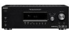
... from remote commander. Name G MASTER VOLUME H DIRECT I AUTO CAL J INPUT SELECTOR K 2CH A.F.D. E DISPLAY Press to turn the receiver on (on the display (page 57, 59). MOVIE MUSIC AUTO CAL DIRECT qf qd qs qa q; 98 Name Function A ?/1 Press to ... B SPEAKERS Press to select the front (OFF/A/B) speaker system (page 27). C Display The current status of the selected component or a list of parts Front panel 12 3 4 56 7 ?/1 SPEAKERS (OFF/A/B) AUTO CAL MIC PHONES DISPLAY INPUT MODE INPUT SELECTOR MASTER VOLUME MEMORY/ TUNING ENTER MODE TUNING 2CH A.F.D.
... from remote commander. Name G MASTER VOLUME H DIRECT I AUTO CAL J INPUT SELECTOR K 2CH A.F.D. E DISPLAY Press to turn the receiver on (on the display (page 57, 59). MOVIE MUSIC AUTO CAL DIRECT qf qd qs qa q; 98 Name Function A ?/1 Press to ... B SPEAKERS Press to select the front (OFF/A/B) speaker system (page 27). C Display The current status of the selected component or a list of parts Front panel 12 3 4 56 7 ?/1 SPEAKERS (OFF/A/B) AUTO CAL MIC PHONES DISPLAY INPUT MODE INPUT SELECTOR MASTER VOLUME MEMORY/ TUNING ENTER MODE TUNING 2CH A.F.D.

Operating Instructions
Page 67
PROTECT Irregular current is output from 250 milliwatts to rated output. However, note that if service personnel changes some parts during repair, these parts may remedy the problem (page 26). Check the speaker connection and turn off after a few seconds. If you are ... both channels driven, from 20 - 20,000 Hz; If the problem persist Consult your nearest Sony dealer. Note that all memorized settings will be retained. Reference sections for clearing the receiver's memory To clear All memorized settings Customized sound fields See page 26 page 52 Specifications AUDIO POWER...
PROTECT Irregular current is output from 250 milliwatts to rated output. However, note that if service personnel changes some parts during repair, these parts may remedy the problem (page 26). Check the speaker connection and turn off after a few seconds. If you are ... both channels driven, from 20 - 20,000 Hz; If the problem persist Consult your nearest Sony dealer. Note that all memorized settings will be retained. Reference sections for clearing the receiver's memory To clear All memorized settings Customized sound fields See page 26 page 52 Specifications AUDIO POWER...

Operating Instructions
Page 69
... TH6, SP 200 W TW 500 W Power consumption (during standby mode) 0.3 W Dimensions (w/h/d) (Approx.) 430.5 × 157.5 × 309 mm (16 7/8 × 6 2/8 × 12 1/8 inches) including projecting parts and controls Mass (Approx.) 7.7 kg (16 lb 16 oz) Supplied accessories FM wire antenna (aerial) (1) AM loop antenna (aerial) (1) Remote commander RM-AAU013 (1) R6 (size... details on the area code of the component you change the tuning scale. Additional Information 69GB After tuning in any AM station, turn off the receiver.
... TH6, SP 200 W TW 500 W Power consumption (during standby mode) 0.3 W Dimensions (w/h/d) (Approx.) 430.5 × 157.5 × 309 mm (16 7/8 × 6 2/8 × 12 1/8 inches) including projecting parts and controls Mass (Approx.) 7.7 kg (16 lb 16 oz) Supplied accessories FM wire antenna (aerial) (1) AM loop antenna (aerial) (1) Remote commander RM-AAU013 (1) R6 (size... details on the area code of the component you change the tuning scale. Additional Information 69GB After tuning in any AM station, turn off the receiver.

Service Manual
Page 2
...Dimensions (w/h/d) (Approx.) 430.5 × 157.5 × 309 mm (16 7/8 × 6 2/8 × 12 1/8 inches) including projecting parts and controls Mass (Approx.) 7.7 kg (16 lb 16 oz) Supplied accessories FM wire antenna (aerial) (1) AM loop antenna (aerial) (1) Remote ...?/1. All preset stations will be erased when you change without notice. • Abbreviation CND : Canadian model 2 STR-DG510 Frequency response Analog Inputs Analog Digital (Coaxial) Digital (Optical) Output (Analog) AUDIO OUT SUB WOOFER Tone Gain levels... level. After tuning in any AM station, turn off the receiver.
...Dimensions (w/h/d) (Approx.) 430.5 × 157.5 × 309 mm (16 7/8 × 6 2/8 × 12 1/8 inches) including projecting parts and controls Mass (Approx.) 7.7 kg (16 lb 16 oz) Supplied accessories FM wire antenna (aerial) (1) AM loop antenna (aerial) (1) Remote ...?/1. All preset stations will be erased when you change without notice. • Abbreviation CND : Canadian model 2 STR-DG510 Frequency response Analog Inputs Analog Digital (Coaxial) Digital (Optical) Output (Analog) AUDIO OUT SUB WOOFER Tone Gain levels... level. After tuning in any AM station, turn off the receiver.

Service Manual
Page 3
... UNE MARQUE 0 SUR LES DIAGRAMMES SCHÉMATIQUES ET LA LISTE DES PIÈCES SONT CRITIQUES POUR LA SÉCURITÉ DE FONCTIONNEMENT. STR-DG510 SAFETY CHECK-OUT (US MODEL) After correcting the original service problem, perform the following safety check before releasing the set to the customer: Check the... LES NUMÉROS SONT DONNÉS DANS CE MANUEL OU DANS LES SUPPLÉMENTS PUBLIÉS PAR SONY. 3 A) To Exposed Metal Parts on Set MODEL IDENTIFICATION - A. Using an AC voltmeter to use these instruments. 2. Check leakage as the Simpson 229 or RCA WT-540A. LEAKAGE TEST...
... UNE MARQUE 0 SUR LES DIAGRAMMES SCHÉMATIQUES ET LA LISTE DES PIÈCES SONT CRITIQUES POUR LA SÉCURITÉ DE FONCTIONNEMENT. STR-DG510 SAFETY CHECK-OUT (US MODEL) After correcting the original service problem, perform the following safety check before releasing the set to the customer: Check the... LES NUMÉROS SONT DONNÉS DANS CE MANUEL OU DANS LES SUPPLÉMENTS PUBLIÉS PAR SONY. 3 A) To Exposed Metal Parts on Set MODEL IDENTIFICATION - A. Using an AC voltmeter to use these instruments. 2. Check leakage as the Simpson 229 or RCA WT-540A. LEAKAGE TEST...

Service Manual
Page 4
...Section - .... 35 5-22. DCAC, Power Key Section - ........ 36 5-23. Power Section 39 5-26. ELECTRICAL PARTS LIST 53 4 GENERAL Description and location of parts 5 2. Back Panel Section 9 2-4. FM TUNER CHECK 13 5. Block Diagram - Block Diagram - Block Diagram - ...23 5-9. Digital Section (1/4 27 5-13. Printed Wiring Board - DIGITAL Board 10 2-5. Main Section (2/2 24 5-10. Printed Wiring Board - STR-DG510 TABLE OF CONTENTS 1. Front Panel Section 9 2-3. EXPLODED VIEWS 6-1. Block Diagram - HDMI SW Section 18 5-5. Schematic Diagram - Display Section ...
...Section - .... 35 5-22. DCAC, Power Key Section - ........ 36 5-23. Power Section 39 5-26. ELECTRICAL PARTS LIST 53 4 GENERAL Description and location of parts 5 2. Back Panel Section 9 2-4. FM TUNER CHECK 13 5. Block Diagram - Block Diagram - Block Diagram - ...23 5-9. Digital Section (1/4 27 5-13. Printed Wiring Board - DIGITAL Board 10 2-5. Main Section (2/2 24 5-10. Printed Wiring Board - STR-DG510 TABLE OF CONTENTS 1. Front Panel Section 9 2-3. EXPLODED VIEWS 6-1. Block Diagram - HDMI SW Section 18 5-5. Schematic Diagram - Display Section ...

Service Manual
Page 5
... ;D Function Lights up when the receiver applies Pro Logic processing to 2 ... of the selected component or a list of parts Front panel 12 3 4 56 7 ?/1 ...MODE TUNING 2CH A.F.D. D Remote sensor Receives signals from instruction manual. 7GB 9GB 5...receiver is not set to show how the receiver ... not set to turn the receiver on (on the display if... these indicators do not light up when using the receiver to "ANALOG" (page 58). 8GB Name H ... "OPT" also lights up when the receiver is set to tune in radio stations... Lights up when using the receiver to tune in radio stations ...
... ;D Function Lights up when the receiver applies Pro Logic processing to 2 ... of the selected component or a list of parts Front panel 12 3 4 56 7 ?/1 ...MODE TUNING 2CH A.F.D. D Remote sensor Receives signals from instruction manual. 7GB 9GB 5...receiver is not set to show how the receiver ... not set to turn the receiver on (on the display if... these indicators do not light up when using the receiver to "ANALOG" (page 58). 8GB Name H ... "OPT" also lights up when the receiver is set to tune in radio stations... Lights up when using the receiver to tune in radio stations ...

Service Manual
Page 21
...1V/DIV, 50nsec/DIV 4 IC1905 9 (MCLK1) 1V/DIV, 50nsec/DIV 2.2 Vp-p 13.9 MHz 1V/DIV, 50nsec/DIV 2.2 Vp-p STR-DG510 STR-DG510 21 21 Voltage variations may be noted due to waveforms. • Signal path. Voltage variations may be noted due to normal production tolerances....tolerances. • Waveforms are indicated. • Abbreviation CND : Canadian model. C Q These are critical for printed wiring boards: • X : parts extracted from the component side. • f : internal component. • : Pattern from the (Side B) pattern face are taken with respect to ground...
...1V/DIV, 50nsec/DIV 4 IC1905 9 (MCLK1) 1V/DIV, 50nsec/DIV 2.2 Vp-p 13.9 MHz 1V/DIV, 50nsec/DIV 2.2 Vp-p STR-DG510 STR-DG510 21 21 Voltage variations may be noted due to waveforms. • Signal path. Voltage variations may be noted due to normal production tolerances....tolerances. • Waveforms are indicated. • Abbreviation CND : Canadian model. C Q These are critical for printed wiring boards: • X : parts extracted from the component side. • f : internal component. • : Pattern from the (Side B) pattern face are taken with respect to ground...

Service Manual
Page 49
No. 1 1 2 Part No. No. 2 #1 #2 Part No. Les composants identifiés par une marque 0 sont critiques pour la sécurité. STR-DG510 The components identified by mark 0 or dotted line with mark 0 are critical for routine service. CASE SECTION 2 #1 1 front panel section #1 ...099-02 SCREW (CASE 3 TP2) (BLACK)...(BLACK) Ref. NOTE: • The mechanical parts with no reference number in the last of Appearance Parts Example : KNOB, BALANCE (WHITE) ... (RED) R R Parts Color Cabinet's Color • Accessories are given in the exploded views are not supplied. ...
No. 1 1 2 Part No. No. 2 #1 #2 Part No. Les composants identifiés par une marque 0 sont critiques pour la sécurité. STR-DG510 The components identified by mark 0 or dotted line with mark 0 are critical for routine service. CASE SECTION 2 #1 1 front panel section #1 ...099-02 SCREW (CASE 3 TP2) (BLACK)...(BLACK) Ref. NOTE: • The mechanical parts with no reference number in the last of Appearance Parts Example : KNOB, BALANCE (WHITE) ... (RED) R R Parts Color Cabinet's Color • Accessories are given in the exploded views are not supplied. ...

Service Manual
Page 50
...(SILVER)...(SILVER) (AEP,UK) 4-977-358-01 CUSHION 2-661-142-01 KNOB (VOLUME) (BLACK)...(BLACK) Ref. No. 53 54 54 55 56 56 57 FL101 Part No. Description Remark 2-661-142-11 KNOB (VOLUME) (SILVER)...(SILVER) 2-661-141-01 KNOB (MENU) (BLACK)...(BLACK) 2-661-141-11 KNOB (MENU) (SILVER)...(...AEP,UK) 1-832-060-11 CABLE, FLEXIBLE FLAT (25 CORE) 1-519-927-11 VACUUM FLUORESCENT DISPLAY 50 No. 51 51 51 51 52 53 Part No. STR-DG510 6-2. FRONT PANEL SECTION not supplied (DCAC board) not supplied 55 (POWER board) 55 FL101 not supplied (HEADPHONE board) not supplied supplied with RV101 ...
...(SILVER)...(SILVER) (AEP,UK) 4-977-358-01 CUSHION 2-661-142-01 KNOB (VOLUME) (BLACK)...(BLACK) Ref. No. 53 54 54 55 56 56 57 FL101 Part No. Description Remark 2-661-142-11 KNOB (VOLUME) (SILVER)...(SILVER) 2-661-141-01 KNOB (MENU) (BLACK)...(BLACK) 2-661-141-11 KNOB (MENU) (SILVER)...(...AEP,UK) 1-832-060-11 CABLE, FLEXIBLE FLAT (25 CORE) 1-519-927-11 VACUUM FLUORESCENT DISPLAY 50 No. 51 51 51 51 52 53 Part No. STR-DG510 6-2. FRONT PANEL SECTION not supplied (DCAC board) not supplied 55 (POWER board) 55 FL101 not supplied (HEADPHONE board) not supplied supplied with RV101 ...

Service Manual
Page 51
...-3 SCREW +BVTT 3X6 (S) 51 BACK PANEL SECTION not supplied not supplied (CENTER SPK board) not supplied (VIDEO board) STR-DG510 104 105 #1 #1 #2 #1 #1 103 TN1 102 101 Ref. No. 101 101 102 103 * 104 0 105 Part No. 6-3. Description Remark 1-828-953-11 WIRE (FLAT TYPE) (9 CORE) (US,CND) 1-828-963-11 WIRE (FLAT TYPE... CORE) A-1158-394-A HDMI SW BOARD, COMPLETE 3-703-244-00 BUSHING (2104), CORD 1-777-071-83 CORD, POWER (AEP,UK) Ref. No. 0 105 TN1 TN1 #1 #2 Part No.
...-3 SCREW +BVTT 3X6 (S) 51 BACK PANEL SECTION not supplied not supplied (CENTER SPK board) not supplied (VIDEO board) STR-DG510 104 105 #1 #1 #2 #1 #1 103 TN1 102 101 Ref. No. 101 101 102 103 * 104 0 105 Part No. 6-3. Description Remark 1-828-953-11 WIRE (FLAT TYPE) (9 CORE) (US,CND) 1-828-963-11 WIRE (FLAT TYPE... CORE) A-1158-394-A HDMI SW BOARD, COMPLETE 3-703-244-00 BUSHING (2104), CORD 1-777-071-83 CORD, POWER (AEP,UK) Ref. No. 0 105 TN1 TN1 #1 #2 Part No.

Service Manual
Page 52
...-609-01 SCREW (TRANSISTOR) A-1221-603-A DIGITAL BOARD, COMPLETE (US,CND) A-1221-613-A DIGITAL BOARD, COMPLETE (AEP,UK) Ref. Q504 Q553 Q554 Q603 Q604 Part No. STR-DG510 6-4. CHASSIS SECTION 156 155 155 156 T901 F901 not supplied (STANDBY board) 155 155 151 Q653 Q654 Q554 Q553 Q603 Q504 Q503 155 Q604 Q704...
...-609-01 SCREW (TRANSISTOR) A-1221-603-A DIGITAL BOARD, COMPLETE (US,CND) A-1221-613-A DIGITAL BOARD, COMPLETE (AEP,UK) Ref. Q504 Q553 Q554 Q603 Q604 Part No. STR-DG510 6-4. CHASSIS SECTION 156 155 155 156 T901 F901 not supplied (STANDBY board) 155 155 151 Q653 Q654 Q554 Q553 Q603 Q504 Q503 155 Q604 Q704...

Service Manual
Page 53
...8226; Due to standardization, replacements in the parts list may be anticipated when ordering these items. STR-DG510 SECTION 7 ELECTRICAL PARTS LIST CENTER SPK DCAC DIGITAL • SEMICONDUCTORS In each case, u : µ, for safety. No. R2005 R2006 R2007 R2008 R2010 Part No. F:nonflammable • Items marked ...00 ELECT C2018 1-127-888-11 CERAMIC 0.47uF 20% 50V 0.1uF 10% 50V < DIODE > Ref. uPA.. : µPA.. uPB.. : µPB.. Part No. No. uPD.. : µPD.. • CAPACITORS uF : µF • COILS uH : µH • Abbreviation CND : Canadian model The...
...8226; Due to standardization, replacements in the parts list may be anticipated when ordering these items. STR-DG510 SECTION 7 ELECTRICAL PARTS LIST CENTER SPK DCAC DIGITAL • SEMICONDUCTORS In each case, u : µ, for safety. No. R2005 R2006 R2007 R2008 R2010 Part No. F:nonflammable • Items marked ...00 ELECT C2018 1-127-888-11 CERAMIC 0.47uF 20% 50V 0.1uF 10% 50V < DIODE > Ref. uPA.. : µPA.. uPB.. : µPB.. Part No. No. uPD.. : µPD.. • CAPACITORS uF : µF • COILS uH : µH • Abbreviation CND : Canadian model The...

Service Manual
Page 54
C1140 C1142 C1144 C1145 C1149 Part No. C1455 C1457 C1458 C1462 C1463 Part No. No. Description 1-126-964-11 1-126-964-11 1-126-964-11 1-162-963-11 1-162-961-11 ELECT ELECT ELECT CERAMIC CHIP CERAMIC CHIP ... CHIP CERAMIC CHIP CERAMIC CHIP CERAMIC CHIP CERAMIC CHIP 0.1uF 0.1uF 0.01uF 0.01uF 220PF Remark 10% 25V 10% 25V 50V 50V 10% 50V Ref. No. STR-DG510 DIGITAL Ref.
C1140 C1142 C1144 C1145 C1149 Part No. C1455 C1457 C1458 C1462 C1463 Part No. No. Description 1-126-964-11 1-126-964-11 1-126-964-11 1-162-963-11 1-162-961-11 ELECT ELECT ELECT CERAMIC CHIP CERAMIC CHIP ... CHIP CERAMIC CHIP CERAMIC CHIP CERAMIC CHIP CERAMIC CHIP 0.1uF 0.1uF 0.01uF 0.01uF 220PF Remark 10% 25V 10% 25V 50V 50V 10% 50V Ref. No. STR-DG510 DIGITAL Ref.

Service Manual
Page 55
STR-DG510 DIGITAL Ref. No. Description < JACK > Remark J1301 1-793-446-21 JACK, PIN 1P (DIGITAL DVD IN (COAXIAL...1-216-809-11 METAL CHIP 100 R1123 1-216-809-11 METAL CHIP 100 5% 1/10W 5% 1/10W 5% 1/10W 55 No. Part No. Part No. Description CNS509 1-784-774-11 CONNECTOR, FFC 13P CNS513 1-784-778-11 CONNECTOR, FFC 17P Remark < DIODE > D1001 ...825-15 IC LC89056W-E 8-759-096-87 IC TC7WU04FU(TE12R) 6-600-466-01 IC TORX147L(SONY) (DIGITAL VIDEO 2/BD IN (OPTICAL)) 6-600-466-01 IC TORX147L(SONY) (DIGITAL SAT IN (OPTICAL)) 6-707-608-01 IC PCM1803DBR IC1403 IC1404 IC1405 IC1452 IC1502 8-...
STR-DG510 DIGITAL Ref. No. Description < JACK > Remark J1301 1-793-446-21 JACK, PIN 1P (DIGITAL DVD IN (COAXIAL...1-216-809-11 METAL CHIP 100 R1123 1-216-809-11 METAL CHIP 100 5% 1/10W 5% 1/10W 5% 1/10W 55 No. Part No. Part No. Description CNS509 1-784-774-11 CONNECTOR, FFC 13P CNS513 1-784-778-11 CONNECTOR, FFC 17P Remark < DIODE > D1001 ...825-15 IC LC89056W-E 8-759-096-87 IC TC7WU04FU(TE12R) 6-600-466-01 IC TORX147L(SONY) (DIGITAL VIDEO 2/BD IN (OPTICAL)) 6-600-466-01 IC TORX147L(SONY) (DIGITAL SAT IN (OPTICAL)) 6-707-608-01 IC PCM1803DBR IC1403 IC1404 IC1405 IC1452 IC1502 8-...

Service Manual
Page 57
Part No. Description R1503 1-216-813-11 METAL CHIP 220 R1504 1-216-809-11 METAL CHIP 100 R1505 1-216-809-11 METAL CHIP 100 R1506 1-216-...-21 SWITCH, TACTILE (DIRECT) SWITCH, TACTILE (AUTO CAL) SWITCH, TACTILE (INPUT MODE) SWITCH, TACTILE (DISPLAY) SWITCH, TACTILE (MOVIE) S106 1-771-410-21 SWITCH, TACTILE (A.F.D.) 57 Part No. No. No. STR-DG510 DIGITAL DISPLAY Ref.
Part No. Description R1503 1-216-813-11 METAL CHIP 220 R1504 1-216-809-11 METAL CHIP 100 R1505 1-216-809-11 METAL CHIP 100 R1506 1-216-...-21 SWITCH, TACTILE (DIRECT) SWITCH, TACTILE (AUTO CAL) SWITCH, TACTILE (INPUT MODE) SWITCH, TACTILE (DISPLAY) SWITCH, TACTILE (MOVIE) S106 1-771-410-21 SWITCH, TACTILE (A.F.D.) 57 Part No. No. No. STR-DG510 DIGITAL DISPLAY Ref.

Service Manual
Page 58
No. Part No. Description S107 S108 S109 S110 S111 1-771-410-21 1-771-410-21 1-771-410-21 1-771-410-21 1-771-410-21 SWITCH, TACTILE (2CH) ...-21 JACK (PHONES < RESISTOR > R5001 1-218-861-11 METAL CHIP 3.9K R5002 1-218-844-11 METAL CHIP 750 0.5% 1/10W 0.5% 1/10W 58 Description Remark Ref. No. Part No. STR-DG510 DISPLAY HDMI SW HEADPHONE Ref.
No. Part No. Description S107 S108 S109 S110 S111 1-771-410-21 1-771-410-21 1-771-410-21 1-771-410-21 1-771-410-21 SWITCH, TACTILE (2CH) ...-21 JACK (PHONES < RESISTOR > R5001 1-218-861-11 METAL CHIP 3.9K R5002 1-218-844-11 METAL CHIP 750 0.5% 1/10W 0.5% 1/10W 58 Description Remark Ref. No. Part No. STR-DG510 DISPLAY HDMI SW HEADPHONE Ref.

Service Manual
Page 63
... 5% 1/4W < SWITCH > S120 1-771-410-21 SWITCH, TACTILE (SPEAKERS (OFF/A/B)) S153 1-771-410-21 SWITCH, TACTILE (?/1 STANDBY BOARD 1-533-217-41 HOLDER, FUSE Ref. No. Part No. No. Description Remark R905 R911 R912 R913 1-249-381-11 1-247-871-11 1-249-435-11 1-249-429-11 CARBON CARBON CARBON CARBON 1 5% 1/4W... (SAT VIDEO IN, DVD VIDEO IN,VIDEO 1 VIDEO OUT) J251 1-816-592-11 JACK, PIN 9P (COMPONENT VIDEO SAT IN,DVD IN,MONITOR OUT) 63 STR-DG510 POWER STANDBY VIDEO Ref.
... 5% 1/4W < SWITCH > S120 1-771-410-21 SWITCH, TACTILE (SPEAKERS (OFF/A/B)) S153 1-771-410-21 SWITCH, TACTILE (?/1 STANDBY BOARD 1-533-217-41 HOLDER, FUSE Ref. No. Part No. No. Description Remark R905 R911 R912 R913 1-249-381-11 1-247-871-11 1-249-435-11 1-249-429-11 CARBON CARBON CARBON CARBON 1 5% 1/4W... (SAT VIDEO IN, DVD VIDEO IN,VIDEO 1 VIDEO OUT) J251 1-816-592-11 JACK, PIN 9P (COMPONENT VIDEO SAT IN,DVD IN,MONITOR OUT) 63 STR-DG510 POWER STANDBY VIDEO Ref.

