Limited Warranty (US Only)
Page 1
... not cover damage due to improper operation or maintenance, connection to improper voltage supply, or attempted repair by anyone other...02 General Stereo/Hifi Components/Tape Decks ® CD Players/Mini Disc Players/Audio Systems Hifi Audio LIMITED WARRANTY Sony Electronics Inc. ("Sony") warrants this Product is determined to be presented to state. After the Warranty Period,...Parts and labor for one (1) year. To obtain warranty service, you may not apply to any Sony authorized service facility. REPAIR OR REPLACEMENT AS PROVIDED UNDER THIS WARRANTY IS THE EXCLUSIVE REMEDY OF THE ...
... not cover damage due to improper operation or maintenance, connection to improper voltage supply, or attempted repair by anyone other...02 General Stereo/Hifi Components/Tape Decks ® CD Players/Mini Disc Players/Audio Systems Hifi Audio LIMITED WARRANTY Sony Electronics Inc. ("Sony") warrants this Product is determined to be presented to state. After the Warranty Period,...Parts and labor for one (1) year. To obtain warranty service, you may not apply to any Sony authorized service facility. REPAIR OR REPLACEMENT AS PROVIDED UNDER THIS WARRANTY IS THE EXCLUSIVE REMEDY OF THE ...
Operating Instructions
Page 2
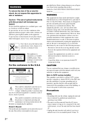
...provides guidelines for an extended period of time. DAV-DX155/DAV-DX255/DAV-DX315 Serial No WARNING This equipment has been tested and found to comply with the instructions, may be connected to the grounding system of the building, as practical. Connect the equipment into the cabinet, unplug the ...(mains) as long as it any changes or modifications not expressly approved in this manual could void your Sony dealer regarding this product. To 2GB This appliance is connected. - Refer to rain or moisture. Do not install the appliance in a confined space, such as chemical...
...provides guidelines for an extended period of time. DAV-DX155/DAV-DX255/DAV-DX315 Serial No WARNING This equipment has been tested and found to comply with the instructions, may be connected to the grounding system of the building, as practical. Connect the equipment into the cabinet, unplug the ...(mains) as long as it any changes or modifications not expressly approved in this manual could void your Sony dealer regarding this product. To 2GB This appliance is connected. - Refer to rain or moisture. Do not install the appliance in a confined space, such as chemical...
Operating Instructions
Page 4
... 62 Changing the Brightness of Contents Welcome 3 About This Manual 6 This System Can Play the Following Discs 7 Getting Started - ADVANCED - Table of the Front Panel Display 62 4GB Step 1: Assembling the Speakers 10 Step 2: Connecting the System and TV 13 Step 3: Positioning the System ...18 Step 4: Performing the Quick Setup 19 Getting Started - BASIC...
... 62 Changing the Brightness of Contents Welcome 3 About This Manual 6 This System Can Play the Following Discs 7 Getting Started - ADVANCED - Table of the Front Panel Display 62 4GB Step 1: Assembling the Speakers 10 Step 2: Connecting the System and TV 13 Step 3: Positioning the System ...18 Step 4: Performing the Quick Setup 19 Getting Started - BASIC...
Operating Instructions
Page 10
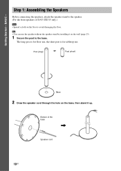
... the speaker cord through the hole on the base, then stand it on the floor to the base. Tip • You can use . Bottom of DAV-DX315 only.) Note • Spread a cloth on the wall (page 23). 1 Secure the post to avoid damaging the floor. The long post is for floor... use, the short post is for tabletop use the speaker without the speaker stand by installing it up. Step 1: Assembling the Speakers Before connecting the speakers, attach the speaker stand to the speaker. (For the front speakers of the base , Speaker cord 10GB Getting Started - BASIC -
... the speaker cord through the hole on the base, then stand it on the floor to the base. Tip • You can use . Bottom of DAV-DX315 only.) Note • Spread a cloth on the wall (page 23). 1 Secure the post to avoid damaging the floor. The long post is for floor... use, the short post is for tabletop use the speaker without the speaker stand by installing it up. Step 1: Assembling the Speakers Before connecting the speakers, attach the speaker stand to the speaker. (For the front speakers of the base , Speaker cord 10GB Getting Started - BASIC -
Operating Instructions
Page 11
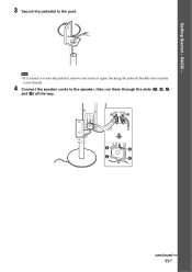
Getting Started - A B C D continued 11GB Securing the pedestal forcibly may ruin the screw threads. 4 Connect the speaker cords to secure the pedestal, remove and secure it is hard to the speaker, then run them through the slots (A, B, C, and D) all the way. Note • If it again. BASIC - 3 Secure the pedestal to the post.
Getting Started - A B C D continued 11GB Securing the pedestal forcibly may ruin the screw threads. 4 Connect the speaker cords to secure the pedestal, remove and secure it is hard to the speaker, then run them through the slots (A, B, C, and D) all the way. Note • If it again. BASIC - 3 Secure the pedestal to the post.
Operating Instructions
Page 13
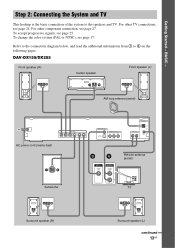
... below, and read the additional information from 1 to the speakers and TV. For other TV connections, see page 17. To change the color system (PAL or NTSC), see page 24. DAV-DX155/DX255 Front speaker (R) Center speaker Front speaker (L) AM loop antenna (aerial) AC power cord (mains lead) ...BA FM wire antenna (aerial) Subwoofer VIDEO IN AUDIO OUT L R TV Surround speaker (R) Surround speaker (L) continued 13GB Getting Started - Step 2: Connecting the System and TV This hookup is the basic connection of the system to 4 on the following pages. For other component...
... below, and read the additional information from 1 to the speakers and TV. For other TV connections, see page 17. To change the color system (PAL or NTSC), see page 24. DAV-DX155/DX255 Front speaker (R) Center speaker Front speaker (L) AM loop antenna (aerial) AC power cord (mains lead) ...BA FM wire antenna (aerial) Subwoofer VIDEO IN AUDIO OUT L R TV Surround speaker (R) Surround speaker (L) continued 13GB Getting Started - Step 2: Connecting the System and TV This hookup is the basic connection of the system to 4 on the following pages. For other component...

Operating Instructions
Page 15
... another speaker cord, such as the label of the speaker cords are reversed, the sound will lack bass and may damage the system. If this , be distorted. 2 Connecting the TV Required cords A Video cord . B Audio cord (not supplied) Yellow White (L/audio) Red (R/audio) continued 15GB ...To prevent this happens, check the speaker connection again. Stripped cords are connected correctly. If the cords are the same color as shown below. Color tube (+) (-) Note • Do not catch the speaker cord...
... another speaker cord, such as the label of the speaker cords are reversed, the sound will lack bass and may damage the system. If this , be distorted. 2 Connecting the TV Required cords A Video cord . B Audio cord (not supplied) Yellow White (L/audio) Red (R/audio) continued 15GB ...To prevent this happens, check the speaker connection again. Stripped cords are connected correctly. If the cords are the same color as shown below. Color tube (+) (-) Note • Do not catch the speaker cord...
Operating Instructions
Page 16
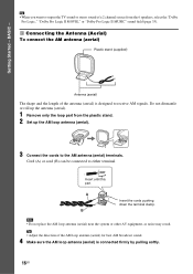
... of a 2 channel source from the plastic stand. 2 Set up the AM loop antenna (aerial). 3 Connect the cords to the AM antenna (aerial) terminals. Note • Do not place the AM loop antenna (aerial) near the system or other AV equipment, as noise may result. Do not dismantle or roll up the... antenna (aerial). 1 Remove only the loop part from the 6 speakers, select the "Dolby Pro Logic," "Dolby Pro Logic II MOVIE," or "Dolby Pro Logic II MUSIC" sound field (page 33). 3 Connecting the Antenna ...
... of a 2 channel source from the plastic stand. 2 Set up the AM loop antenna (aerial). 3 Connect the cords to the AM antenna (aerial) terminals. Note • Do not place the AM loop antenna (aerial) near the system or other AV equipment, as noise may result. Do not dismantle or roll up the... antenna (aerial). 1 Remove only the loop part from the 6 speakers, select the "Dolby Pro Logic," "Dolby Pro Logic II MOVIE," or "Dolby Pro Logic II MUSIC" sound field (page 33). 3 Connecting the Antenna ...

Operating Instructions
Page 17
... FM reception, use a 75-ohm coaxial cable (not supplied) to connect the system to fully extend the FM wire antenna (aerial). • After connecting the FM wire antenna (aerial), keep it as horizontal as shown below. To connect the FM wire antenna (aerial) Connect the FM wire antenna (aerial) to NTSC. 17GB Tip • If...
... FM reception, use a 75-ohm coaxial cable (not supplied) to connect the system to fully extend the FM wire antenna (aerial). • After connecting the FM wire antenna (aerial), keep it as horizontal as shown below. To connect the FM wire antenna (aerial) Connect the FM wire antenna (aerial) to NTSC. 17GB Tip • If...

Operating Instructions
Page 19
... and perform again (page 21). 4 Press ENTER without inserting a disc. The Setup Display for using the system. SPEAKER FORMATION STANDARD continued 19GB The system displays the menu and subtitles in the on-screen display appears. 7 Press X/x to select the setting that the...If you perform the Quick Setup. x If you have a wide-screen TV or a 4:3 standard TV with the headphones connected. • Make sure that the function is set to be connected appears. BASIC - "/1 C/X/x/c ENTER DISPLAY LANGUAGE SETUP OSD: MENU: AUDIO: SUBTITLE: ENGLISH ENGLISH FRENCH SPANISH PORTUGUESE 5 Press...
... and perform again (page 21). 4 Press ENTER without inserting a disc. The Setup Display for using the system. SPEAKER FORMATION STANDARD continued 19GB The system displays the menu and subtitles in the on-screen display appears. 7 Press X/x to select the setting that the...If you perform the Quick Setup. x If you have a wide-screen TV or a 4:3 standard TV with the headphones connected. • Make sure that the function is set to be connected appears. BASIC - "/1 C/X/x/c ENTER DISPLAY LANGUAGE SETUP OSD: MENU: AUDIO: SUBTITLE: ENGLISH ENGLISH FRENCH SPANISH PORTUGUESE 5 Press...

Operating Instructions
Page 20
...between the speakers and the calibration mic. YES NO Note • If measurement fails, follow the message then retry [AUTO CALIBRATION]. AUTO CALIBRATION Connect calibration mic. To quit the Quick Setup Press DISPLAY in the measurement area and making noise during the measurement. Tip • If you want.... Set up the calibration mic at the ear level using a tripod, etc. (not supplied). You cannot turn the volume down. BASIC - 10 Connect the calibration mic to the A.CAL MIC jack on the front panel and press X/x to change the position of the speakers, reset the speaker settings...
...between the speakers and the calibration mic. YES NO Note • If measurement fails, follow the message then retry [AUTO CALIBRATION]. AUTO CALIBRATION Connect calibration mic. To quit the Quick Setup Press DISPLAY in the measurement area and making noise during the measurement. Tip • If you want.... Set up the calibration mic at the ear level using a tripod, etc. (not supplied). You cannot turn the volume down. BASIC - 10 Connect the calibration mic to the A.CAL MIC jack on the front panel and press X/x to change the position of the speakers, reset the speaker settings...

Operating Instructions
Page 22
... mode. The AMP menu turns off . 4 Press ENTER. Note • When you press "/1 on the system, the demonstration does not turn off. • When you set to off, the system saves power in the AMP menu to on, the demonstration does not turn off the demonstration, set the demonstration... mode to select the setting. • DEMO ON: sets the demonstration mode on the remote. Setting the demonstration mode on/off . X/x/c ENTER AMP MENU After connecting the AC...
... mode. The AMP menu turns off . 4 Press ENTER. Note • When you press "/1 on the system, the demonstration does not turn off. • When you set to off, the system saves power in the AMP menu to on, the demonstration does not turn off the demonstration, set the demonstration... mode to select the setting. • DEMO ON: sets the demonstration mode on the remote. Setting the demonstration mode on/off . X/x/c ENTER AMP MENU After connecting the AC...
Operating Instructions
Page 24
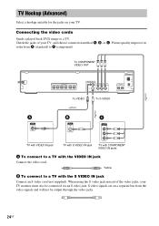
...C Y PB/CB PR/CR TV with VIDEO IN jack TV with S VIDEO IN jack TV with COMPONENT VIDEO IN jacks A To connect to a TV with the S VIDEO IN jack Connect an S video cord (not supplied). S video signals are on your TV. Picture quality improves in order from the video signals and ...will not be connected via an S video jack. Yellow B To connect to a TV. Connecting the video cords Sends a played back DVD image to a TV with...
...C Y PB/CB PR/CR TV with VIDEO IN jack TV with S VIDEO IN jack TV with COMPONENT VIDEO IN jacks A To connect to a TV with the S VIDEO IN jack Connect an S video cord (not supplied). S video signals are on your TV. Picture quality improves in order from the video signals and ...will not be connected via an S video jack. Yellow B To connect to a TV. Connecting the video cords Sends a played back DVD image to a TV with...
Operating Instructions
Page 25
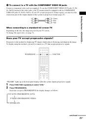
...that accepts progressive signals. Getting Started - Does your TV screen. If your TV monitor must be equipped with the COMPONENT VIDEO IN jacks Connect a component video cord (not supplied). Progressive is the method for displaying TV images which reduces flickering, and sharpens the image. To change... method, you must use the COMPONENT VIDEO OUT jacks (Y, PB/ CB, PR/CR) instead of the system to a TV with via COMPONENT VIDEO IN jacks (Y, PB/CB, PR/CR). C To connect to progressive format (page 25). Each time you press PROGRESSIVE, the display changes as follows: t P ...
...that accepts progressive signals. Getting Started - Does your TV screen. If your TV monitor must be equipped with the COMPONENT VIDEO IN jacks Connect a component video cord (not supplied). Progressive is the method for displaying TV images which reduces flickering, and sharpens the image. To change... method, you must use the COMPONENT VIDEO OUT jacks (Y, PB/ CB, PR/CR) instead of the system to a TV with via COMPONENT VIDEO IN jacks (Y, PB/CB, PR/CR). C To connect to progressive format (page 25). Each time you press PROGRESSIVE, the display changes as follows: t P ...

Operating Instructions
Page 26
... the COMPONENT VIDEO OUT jacks. the TV is connected to the COMPONENT VIDEO OUT jacks, and, - Note that the picture will appear if you select these settings when either of images may appear unnatural ... in progressive format, the progressive signals need to the conversion process when output through the COMPONENT VIDEO OUT jacks. Select this if the image is connected to "PROGRESSIVE AUTO" or "PROGRESSIVE VIDEO," images from TV, such as they are not met. your screen when output in the interlace format. 26GB Even...
... the COMPONENT VIDEO OUT jacks. the TV is connected to the COMPONENT VIDEO OUT jacks, and, - Note that the picture will appear if you select these settings when either of images may appear unnatural ... in progressive format, the progressive signals need to the conversion process when output through the COMPONENT VIDEO OUT jacks. Select this if the image is connected to "PROGRESSIVE AUTO" or "PROGRESSIVE VIDEO," images from TV, such as they are not met. your screen when output in the interlace format. 26GB Even...
Operating Instructions
Page 27
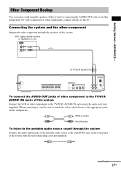
...portable audio source sound through the speakers of this system by connecting the AUDIO OUT jacks of other component through the system Connect the audio output jacks of the portable audio source to the TV/VCR (AUDIO IN) jacks of the system with the stereo mini-plug cord (not supplied).... component to the AUDIO IN jack on the components. continued 27GB Connecting the system and the other component Outputs the other components, connect directly to the TV/VCR (AUDIO IN) jacks using the speakers of this system. When connecting a cord, be sure to match the color-coded sleeves to ...
...portable audio source sound through the speakers of this system by connecting the AUDIO OUT jacks of other component through the system Connect the audio output jacks of the portable audio source to the TV/VCR (AUDIO IN) jacks of the system with the stereo mini-plug cord (not supplied).... component to the AUDIO IN jack on the components. continued 27GB Connecting the system and the other component Outputs the other components, connect directly to the TV/VCR (AUDIO IN) jacks using the speakers of this system. When connecting a cord, be sure to match the color-coded sleeves to ...

Operating Instructions
Page 28
Note • Be sure to make connections securely to select "AUDIO." Press FUNCTION to avoid hum and noise. 28GB Press SOUND FIELD repeatedly until "A.F.D. To cancel, select other than "A.F.D. STD." Connect the portable audio source. Tip • When listening to MP3 format recordings using a portable audio source, you can enhance the sound. STD" appears in the front panel display.
Note • Be sure to make connections securely to select "AUDIO." Press FUNCTION to avoid hum and noise. 28GB Press SOUND FIELD repeatedly until "A.F.D. To cancel, select other than "A.F.D. STD." Connect the portable audio source. Tip • When listening to MP3 format recordings using a portable audio source, you can enhance the sound. STD" appears in the front panel display.

Operating Instructions
Page 29
..., and then press A. Perform next Step while "*DISC-1* (eg., 2-5)" flashes. 5 Press A. 6 Load a disc. Tip • The DISC 1-5 indicators change color as this system. 3 Press "/1. Basic Operations Disc tray DISC 1-5 Connect headphones DISC SKIP "/1 FUNCTION MUTING VOLUME +/- ./> / H x X Depending on the DVD VIDEO or VIDEO CD, some operations may not appear on the TV...
..., and then press A. Perform next Step while "*DISC-1* (eg., 2-5)" flashes. 5 Press A. 6 Load a disc. Tip • The DISC 1-5 indicators change color as this system. 3 Press "/1. Basic Operations Disc tray DISC 1-5 Connect headphones DISC SKIP "/1 FUNCTION MUTING VOLUME +/- ./> / H x X Depending on the DVD VIDEO or VIDEO CD, some operations may not appear on the TV...

Operating Instructions
Page 31
... FUNCTION, the mode of the system changes in the front panel display, then press ENTER or c. 4 Press X/x to the AUDIO IN jack on the rear of the unit or to select a setting. • ATT ON: attenuates the input level. Selecting the connected component You can change the input...TV/VCR t AUDIO t ... The setting is not a malfunction and will depend on the rear panel. Refer to the TV/VCR jacks on the component connected. This is reflected. 6 Press AMP MENU. Basic Operations Enjoying the Radio or Other Components X/x/c ENTER FUNCTION AMP MENU 1 Press FUNCTION repeatedly until "TV/ ...
... FUNCTION, the mode of the system changes in the front panel display, then press ENTER or c. 4 Press X/x to the AUDIO IN jack on the rear of the unit or to select a setting. • ATT ON: attenuates the input level. Selecting the connected component You can change the input...TV/VCR t AUDIO t ... The setting is not a malfunction and will depend on the rear panel. Refer to the TV/VCR jacks on the component connected. This is reflected. 6 Press AMP MENU. Basic Operations Enjoying the Radio or Other Components X/x/c ENTER FUNCTION AMP MENU 1 Press FUNCTION repeatedly until "TV/ ...
Operating Instructions
Page 32
... the movie or music mode is selected, "MOVIE" or "MUSIC" is underlined. • AUTO: selects the mode automatically to the system. 32GB The default setting is displayed in this system. When you connect headphones to produce the sound effect depending on the disc. • MOVIE: provides the sound for movies. • MUSIC: provides...
... the movie or music mode is selected, "MOVIE" or "MUSIC" is underlined. • AUTO: selects the mode automatically to the system. 32GB The default setting is displayed in this system. When you connect headphones to produce the sound effect depending on the disc. • MOVIE: provides the sound for movies. • MUSIC: provides...


