
Child Safety: It Makes A Difference Where Your TV Stands
Page 1
... purchases and are improperly secured or inappropriately situated on the proper TV stands. Sometimes televisions are not always supported on dressers, bookcases, shelves, desks, audio speakers, chests or carts.
... purchases and are improperly secured or inappropriately situated on the proper TV stands. Sometimes televisions are not always supported on dressers, bookcases, shelves, desks, audio speakers, chests or carts.

Operating Instructions
Page 4
...image displayed on for about half an hour until the moisture evaporates. 4 • When you do, the speakers may be damaged. • For power saving purposes, the system can overheat and malfunction. • Do not place the system on a soft surface such as alcohol or benzine. On placement • Place the...poor as it is not disconnected from the AC power source (mains) as long as this case, remove the disc and leave the system turned on your nearest Sony dealer. Do not place the unit in a location with a mild detergent solution. Though the LED remains lit for an extended period...
...image displayed on for about half an hour until the moisture evaporates. 4 • When you do, the speakers may be damaged. • For power saving purposes, the system can overheat and malfunction. • Do not place the system on a soft surface such as alcohol or benzine. On placement • Place the...poor as it is not disconnected from the AC power source (mains) as long as this case, remove the disc and leave the system turned on your nearest Sony dealer. Do not place the unit in a location with a mild detergent solution. Though the LED remains lit for an extended period...

Operating Instructions
Page 5
... (Magic Pad 15 Getting Started 17 Quick Overview 17 Unpacking ...17 Inserting Batteries into the Remote 18 Step 1: Speaker System Hookup 18 Step 2: Antenna Hookups 21 Step 3: TV and Video Component Hookups 23 Speaker Setup 25 Presetting Radio Stations 30 Playing Discs 32 Playing Discs 32 Resuming Playback from the Point Where You...
... (Magic Pad 15 Getting Started 17 Quick Overview 17 Unpacking ...17 Inserting Batteries into the Remote 18 Step 1: Speaker System Hookup 18 Step 2: Antenna Hookups 21 Step 3: TV and Video Component Hookups 23 Speaker Setup 25 Presetting Radio Stations 30 Playing Discs 32 Playing Discs 32 Resuming Playback from the Point Where You...
Operating Instructions
Page 6
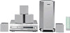
... the TV with the Supplied Remote 60 Watching the Video or other Unit 61 Listening to the Radio 62 Using the Radio Data System (RDS) (Only for the European models 63 Naming Preset Stations 63 Settings and Adjustments 65 Using the Setup Display 65 Setting the...Display or Sound Track Language (LANGUAGE SETUP 66 Settings for the Display (SCREEN SETUP 67 Custom Settings (CUSTOM SETUP 68 Settings for the Speakers (SPEAKER SETUP 69 Additional Information 73 Troubleshooting 73 Self-diagnosis Function (When letters/numbers appear in the display 76 Glossary ...76 Specifications 79 Language...
... the TV with the Supplied Remote 60 Watching the Video or other Unit 61 Listening to the Radio 62 Using the Radio Data System (RDS) (Only for the European models 63 Naming Preset Stations 63 Settings and Adjustments 65 Using the Setup Display 65 Setting the...Display or Sound Track Language (LANGUAGE SETUP 66 Settings for the Display (SCREEN SETUP 67 Custom Settings (CUSTOM SETUP 68 Settings for the Speakers (SPEAKER SETUP 69 Additional Information 73 Troubleshooting 73 Self-diagnosis Function (When letters/numbers appear in the display 76 Glossary ...76 Specifications 79 Language...
Operating Instructions
Page 13
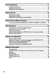
Rear Panel VIDEO OUT VIDEO IN VIDEO IN AM A U D I O OUT A U D I O I N A U D I O I N SVIDEO (DVD ONLY) COAXIAL FM 75Ω L R VIDEO 1 L OPTICAL DIGITAL DIGITAL (CD ONLY) R IN DIGITAL OUT VIDEO MONITOR OUT FRONT R CENTER FRONT L VIDEO 2 Y PB/B-Y PR/R-Y COMPONENT VIDEO OUT REAR R WOOFER REAR L SPEAKER 1 AM antenna (21) 2 VIDEO 1 jacks (23) 3 VIDEO 2 jacks (23) 4 DIGITAL IN (OPTICAL) jack (24) 5 DIGITAL OUT (OPTICAL) jack 6 MONITOR OUT (VIDEO/S VIDEO) jacks (23) 7 COMPONENT VIDEO OUT jacks (23) 8 SPEAKER jacks (19) 9 FM 75Ω COAXIAL antenna jack (22) continued 13
Rear Panel VIDEO OUT VIDEO IN VIDEO IN AM A U D I O OUT A U D I O I N A U D I O I N SVIDEO (DVD ONLY) COAXIAL FM 75Ω L R VIDEO 1 L OPTICAL DIGITAL DIGITAL (CD ONLY) R IN DIGITAL OUT VIDEO MONITOR OUT FRONT R CENTER FRONT L VIDEO 2 Y PB/B-Y PR/R-Y COMPONENT VIDEO OUT REAR R WOOFER REAR L SPEAKER 1 AM antenna (21) 2 VIDEO 1 jacks (23) 3 VIDEO 2 jacks (23) 4 DIGITAL IN (OPTICAL) jack (24) 5 DIGITAL OUT (OPTICAL) jack 6 MONITOR OUT (VIDEO/S VIDEO) jacks (23) 7 COMPONENT VIDEO OUT jacks (23) 8 SPEAKER jacks (19) 9 FM 75Ω COAXIAL antenna jack (22) continued 13

Operating Instructions
Page 17
...system right away. For selecting the aspect ratio of the TV to be connected, refer to the page 66. For selecting a language used in the on-screen display, refer to the page 67. Getting Started Getting Started Quick Overview This chapter presents a quick overview so you have the following items: • Speakers... (5) • Subwoofer (1) • AM loop antenna (1) • FM wire antenna (1) • Speaker cords (5m × 4, 15m × 2) (16ft. × 4, 49ft. ×...
...system right away. For selecting the aspect ratio of the TV to be connected, refer to the page 66. For selecting a language used in the on-screen display, refer to the page 67. Getting Started Getting Started Quick Overview This chapter presents a quick overview so you have the following items: • Speakers... (5) • Subwoofer (1) • AM loop antenna (1) • FM wire antenna (1) • Speaker cords (5m × 4, 15m × 2) (16ft. × 4, 49ft. ×...
Operating Instructions
Page 18
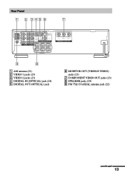
... the remote sensor on the system. Inserting Batteries into the remote casing, particularly when replacing the batteries. • Do not expose the remote sensor to direct light from battery leakage and corrosion. Do not connect any speakers other than those of time,...the supplied remote. Doing so may cause a malfunction. • If you do not use a new battery with this system. Step 1: Speaker System Hookup Connect the supplied speaker system using the supplied speaker cords by matching the 3 and # ends on page 25. Grey (+) (+) (-) Colour tube (-) Black 18 Insert two...
... the remote sensor on the system. Inserting Batteries into the remote casing, particularly when replacing the batteries. • Do not expose the remote sensor to direct light from battery leakage and corrosion. Do not connect any speakers other than those of time,...the supplied remote. Doing so may cause a malfunction. • If you do not use a new battery with this system. Step 1: Speaker System Hookup Connect the supplied speaker system using the supplied speaker cords by matching the 3 and # ends on page 25. Grey (+) (+) (-) Colour tube (-) Black 18 Insert two...
Operating Instructions
Page 19
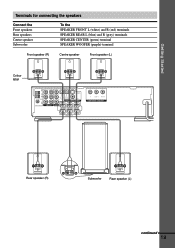
Getting Started Terminals for connecting the speakers Connect the Front speakers Rear speakers Centre speaker Subwoofer To the SPEAKER FRONT L (white) and R (red) terminals SPEAKER REAR L (blue) and R (grey) terminals SPEAKER CENTER (green) terminal SPEAKER WOOFER (purple) terminal Front speaker (R) Centre speaker Front speaker (L) Colour label VIDEO OUT VIDEO IN VIDEO IN AM A U D I O OUT A U D I O I N A U D I O I N SVIDEO (DVD ONLY) COAXIAL FM 75Ω L R VIDEO...
Getting Started Terminals for connecting the speakers Connect the Front speakers Rear speakers Centre speaker Subwoofer To the SPEAKER FRONT L (white) and R (red) terminals SPEAKER REAR L (blue) and R (grey) terminals SPEAKER CENTER (green) terminal SPEAKER WOOFER (purple) terminal Front speaker (R) Centre speaker Front speaker (L) Colour label VIDEO OUT VIDEO IN VIDEO IN AM A U D I O OUT A U D I O I N A U D I O I N SVIDEO (DVD ONLY) COAXIAL FM 75Ω L R VIDEO...
Operating Instructions
Page 20
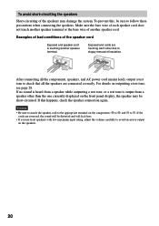
... components: 3 to 3, and # to avoid excessive output on the speakers. 20 To avoid short-circuiting the speakers Short-circuiting of the speakers may be short-circuited. To prevent this happens, check the speaker connection again. If this , be distorted and will lack bass. •...test tone is touching another speaker cord. Examples of bad conditions of the speaker cord Exposed end speaker cord is output from a speaker other due to follow these precautions when connecting the speakers. For details on the front panel display, the speaker may damage the system. Make sure the bare ...
... components: 3 to 3, and # to avoid excessive output on the speakers. 20 To avoid short-circuiting the speakers Short-circuiting of the speakers may be short-circuited. To prevent this happens, check the speaker connection again. If this , be distorted and will lack bass. •...test tone is touching another speaker cord. Examples of bad conditions of the speaker cord Exposed end speaker cord is output from a speaker other due to follow these precautions when connecting the speakers. For details on the front panel display, the speaker may damage the system. Make sure the bare ...

Operating Instructions
Page 21
...) VIDEO R IN DIGITAL OUT MONITOR OUT FRONT R CENTER FRONT L VIDEO 2 Y PB/B-Y PR/R-Y COMPONENT VIDEO OUT REAR R WOOFER REAR L SPEAKER Notes • To prevent noise pickup, keep the AM loop antenna away from the system and other components. • Be sure to fully extend the FM wire antenna. • After connecting the FM...
...) VIDEO R IN DIGITAL OUT MONITOR OUT FRONT R CENTER FRONT L VIDEO 2 Y PB/B-Y PR/R-Y COMPONENT VIDEO OUT REAR R WOOFER REAR L SPEAKER Notes • To prevent noise pickup, keep the AM loop antenna away from the system and other components. • Be sure to fully extend the FM wire antenna. • After connecting the FM...
Operating Instructions
Page 23
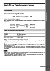
z When you are on the components. If the unit is output from the front L/R speakers, but not from the VIDEO 1 VIDEO OUT and AUDIO OUT L/R jacks. • When you select VIDEO 1 using a component video cord (not supplied) or three video ... bus from the video signals and will enjoy accurate colour reproduction and high quality images. continued 23 S-video signals are connecting the monitor, projector, or AV amplifier (receiver) having component video input jacks (Y, PB, PR) Connect the component via an S-video jack. Yellow (Video) White (L/audio) Red (R/audio) Yellow (Video) White...
z When you are on the components. If the unit is output from the front L/R speakers, but not from the VIDEO 1 VIDEO OUT and AUDIO OUT L/R jacks. • When you select VIDEO 1 using a component video cord (not supplied) or three video ... bus from the video signals and will enjoy accurate colour reproduction and high quality images. continued 23 S-video signals are connecting the monitor, projector, or AV amplifier (receiver) having component video input jacks (Y, PB, PR) Connect the component via an S-video jack. Yellow (Video) White (L/audio) Red (R/audio) Yellow (Video) White...

Operating Instructions
Page 24
... 75Ω L R VIDEO 1 L OPTICAL DIGITAL DIGITAL (CD ONLY) R IN DIGITAL OUT VIDEO MONITOR OUT FRONT R CENTER FRONT L Y PB/B-Y PR/R-Y COMPONENT VIDEO OUT REAR R WOOFER REAR L SPEAKER IN OUT VIDEO VIDEO IN OUT AUDIO AUDIO IN OUT L R OUT VIDEO OUT AUDIO OUT L R OUT OUTPUT OPTICAL IN INPUT VIDEO IN IN COMPOMENT VIDEO... monitor Equipment with the OPTICAL jack The digital satellite receiver can accept both the digital and analog signals. To reset to hold the X button until DAV-C700 appears on the system.
... 75Ω L R VIDEO 1 L OPTICAL DIGITAL DIGITAL (CD ONLY) R IN DIGITAL OUT VIDEO MONITOR OUT FRONT R CENTER FRONT L Y PB/B-Y PR/R-Y COMPONENT VIDEO OUT REAR R WOOFER REAR L SPEAKER IN OUT VIDEO VIDEO IN OUT AUDIO AUDIO IN OUT L R OUT VIDEO OUT AUDIO OUT L R OUT OUTPUT OPTICAL IN INPUT VIDEO IN IN COMPOMENT VIDEO... monitor Equipment with the OPTICAL jack The digital satellite receiver can accept both the digital and analog signals. To reset to hold the X button until DAV-C700 appears on the system.

Operating Instructions
Page 25
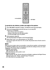
... of your listening position, then set the balance and level. continued 25 Use the test tone to adjust the speaker volumes to the side, depending on the shape of the speakers from the listening position than the subwoofer should be placed from 1.0 to 15.0 meters (3 to 50 feet) ...(A) from the listening position. However, if necessary, this system allows you or to the same level. The front speakers can place the subwoofer in the ...
... of your listening position, then set the balance and level. continued 25 Use the test tone to adjust the speaker volumes to the side, depending on the shape of the speakers from the listening position than the subwoofer should be placed from 1.0 to 15.0 meters (3 to 50 feet) ...(A) from the listening position. However, if necessary, this system allows you or to the same level. The front speakers can place the subwoofer in the ...
Operating Instructions
Page 26
... 3 to be set in 9 SP. NO: Select this if no rear speaker is stored in the system. Distance of the rear and centre speakers - SETUP. YES: Normally select this . - If you do not connect centre or rear speakers, or move the rear speakers, set other parameters in 9 SP. Specify the position and height to display...
... 3 to be set in 9 SP. NO: Select this if no rear speaker is stored in the system. Distance of the rear and centre speakers - SETUP. YES: Normally select this . - If you do not connect centre or rear speakers, or move the rear speakers, set other parameters in 9 SP. Specify the position and height to display...

Operating Instructions
Page 27
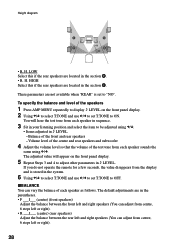
...NONE" in "REAR," specify the position and height of the rear speakers. Position diagram A B 90 A 45 B 20 • R. P. D. 3.4 m (12 ft) (rear speakers distance) Rear speaker distance can be set in 0.2 m (1 foot) steps from a distance equal to the front speaker distance to a distance 4.6 m (15 feet) closer to your...you select anything other model's displays metric measurements only. D. 5 m (17 ft) (front speakers distance) Front speaker distance can vary the distance of each of the front or rear speakers are not placed an equal distance from 1.0 to 15.0 m (3 to your listening position. ...
...NONE" in "REAR," specify the position and height of the rear speakers. Position diagram A B 90 A 45 B 20 • R. P. D. 3.4 m (12 ft) (rear speakers distance) Rear speaker distance can be set in 0.2 m (1 foot) steps from a distance equal to the front speaker distance to a distance 4.6 m (15 feet) closer to your...you select anything other model's displays metric measurements only. D. 5 m (17 ft) (front speakers distance) Front speaker distance can vary the distance of each of the front or rear speakers are not placed an equal distance from 1.0 to 15.0 m (3 to your listening position. ...
Operating Instructions
Page 28
...NO". These parameters are in the parentheses. • F ___I___ (centre) (front speakers) Adjust the balance between the front left and right speakers (You can adjust from the display and is set T.TONE to adjust other parameters in the system. 6 Using X/x to select T.TONE and use C/c to set T.TONE to ...ON. Volume level of the centre and rear speakers and subwoofer 4 Adjust the volume level so that the volume of the speakers 1 Press AMP MENU repeatedly to display 9 LEVEL...
...NO". These parameters are in the parentheses. • F ___I___ (centre) (front speakers) Adjust the balance between the front left and right speakers (You can adjust from the display and is set T.TONE to adjust other parameters in the system. 6 Using X/x to select T.TONE and use C/c to set T.TONE to ...ON. Volume level of the centre and rear speakers and subwoofer 4 Adjust the volume level so that the volume of the speakers 1 Press AMP MENU repeatedly to display 9 LEVEL...
Operating Instructions
Page 29
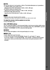
...select Y by pressing ENTER, "Really? Y" appears. Getting Started xLEVEL You can vary the level of each speaker as preset stations and station names will be cleared, and speaker parameters will be defaulted. 29 Other AMP MENU settings You can change the brightness of all settings such as follows...Depending on the settings of the front panel display, clear the preset stations and the station names, and set the speaker parameters back to display 9 CUSTOMIZE. is displayed and all the speakers at one time Use the VOLUME control. Use X/x to +6 dB, 1 dB steps). • R. The ...
...select Y by pressing ENTER, "Really? Y" appears. Getting Started xLEVEL You can vary the level of each speaker as preset stations and station names will be cleared, and speaker parameters will be defaulted. 29 Other AMP MENU settings You can change the brightness of all settings such as follows...Depending on the settings of the front panel display, clear the preset stations and the station names, and set the speaker parameters back to display 9 CUSTOMIZE. is displayed and all the speakers at one time Use the VOLUME control. Use X/x to +6 dB, 1 dB steps). • R. The ...
Operating Instructions
Page 47
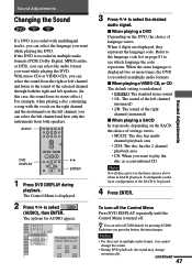
...time you want while playing the DVD. If the DVD is underlined. • STEREO: The standard stereo sound • 1/L: The sound of the left speakers. (In this case, the sound loses its stereo effect.) For example, when playing a disc containing a song with multilingual tracks, you can select the... of the right channel (monaural) xWhen playing a SACD In stop mode, depending on the SACD, the choice of the selected channel through both speakers. With stereo CDs or VIDEO CDs, you can select AUDIO directly by pressing AUDIO. Sound Adjustments Changing the Sound If a DVD is turned off...
...time you want while playing the DVD. If the DVD is underlined. • STEREO: The standard stereo sound • 1/L: The sound of the left speakers. (In this case, the sound loses its stereo effect.) For example, when playing a disc containing a song with multilingual tracks, you can select the... of the right channel (monaural) xWhen playing a SACD In stop mode, depending on the SACD, the choice of the selected channel through both speakers. With stereo CDs or VIDEO CDs, you can select AUDIO directly by pressing AUDIO. Sound Adjustments Changing the Sound If a DVD is turned off...

Operating Instructions
Page 49
...sound characteristics of the Sony Pictures Entertainment's mixing studio using the 3D sound imaging of V. MULTI DIMENSION (page 50) to DVD with lots of actual rear speakers. For example, if you want appears on the system to create 5 sets of virtual speakers surrounding the listener ...from a single pair of actual rear speakers. CINEMA STUDIO EX A* Reproduces the sound characteristics of the Sony Pictures Entertainment's classic editing ...
...sound characteristics of the Sony Pictures Entertainment's mixing studio using the 3D sound imaging of V. MULTI DIMENSION (page 50) to DVD with lots of actual rear speakers. For example, if you want appears on the system to create 5 sets of virtual speakers surrounding the listener ...from a single pair of actual rear speakers. CINEMA STUDIO EX A* Reproduces the sound characteristics of the Sony Pictures Entertainment's classic editing ...
Operating Instructions
Page 50
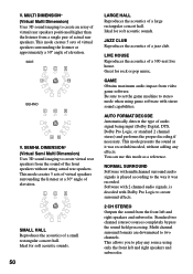
... or standard 2 channel stereo) and performs the proper decoding if necessary. GAME Obtains maximum audio impact from a single pair of virtual rear speakers positioned higher than the listener from video game software. AUTO FORMAT DECODE Automatically detects the type of a 300-seat live house. Standard two ... jazz club. NORMAL SURROUND Software with multichannel surround audio signals is decoded with Dolby Pro Logic to create an array of actual rear speakers. JAZZ CLUB Reproduces the acoustics of a small rectangular concert hall. Great for rock or pop music. Be sure to set the game...
... or standard 2 channel stereo) and performs the proper decoding if necessary. GAME Obtains maximum audio impact from a single pair of virtual rear speakers positioned higher than the listener from video game software. AUTO FORMAT DECODE Automatically detects the type of a 300-seat live house. Standard two ... jazz club. NORMAL SURROUND Software with multichannel surround audio signals is decoded with Dolby Pro Logic to create an array of actual rear speakers. JAZZ CLUB Reproduces the acoustics of a small rectangular concert hall. Great for rock or pop music. Be sure to set the game...


