
Service Manual
Page 1
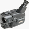
.../TRV46/TRV46PK MICROFILM Video camera recorder System Video recording system 2 Rotary heads Helical scanning FM system Audio recording system Rotary heads, FM system Video signal NTSC color, EIA standards Usable cassette 8mm video format cassette CCD-TR315/TR416/TR416PK CCD-TRV16/TRV16PK : standard 8 CCD-TR516/TR516PK/TR716 CCD-TRV36/TRV36PK/TRV43/TRV46/ TRV46PK : Hi8 Recording / Playback time...
.../TRV46/TRV46PK MICROFILM Video camera recorder System Video recording system 2 Rotary heads Helical scanning FM system Audio recording system Rotary heads, FM system Video signal NTSC color, EIA standards Usable cassette 8mm video format cassette CCD-TR315/TR416/TR416PK CCD-TRV16/TRV16PK : standard 8 CCD-TR516/TR516PK/TR716 CCD-TRV36/TRV36PK/TRV43/TRV46/ TRV46PK : Hi8 Recording / Playback time...

Service Manual
Page 2
...ROS SONT DONNÉS DANS CE MANUEL OU DANS LES SUPPLÉMENTS PUBLIÉS PAR SONY. SAFETY CHECK-OUT After correcting the original service problem, perform the following safety checks before releasing...(AC power adaptor) Averege power consumption(when using the battery pack) During camera recording CCD-TR416/TR416PK/TR516/ TR516PK : 2.4 W CCD-TR315/TR716 : 2.5 W During camera recording using LCD CCD-TRV16/TRV16PK/TRV36/ TRV36PK : 3.1 W CCD-TRV43/TRV46/TRV46PK : 3.2 W Viewfinder CCD-TRV16/TRV16PK/TRV36/ TRV36PK : 2.5 W CCD-TRV43/TRV46/TRV46PK : 2.6 W Operating temperature 32°FC to 104&#...
...ROS SONT DONNÉS DANS CE MANUEL OU DANS LES SUPPLÉMENTS PUBLIÉS PAR SONY. SAFETY CHECK-OUT After correcting the original service problem, perform the following safety checks before releasing...(AC power adaptor) Averege power consumption(when using the battery pack) During camera recording CCD-TR416/TR416PK/TR516/ TR516PK : 2.4 W CCD-TR315/TR716 : 2.5 W During camera recording using LCD CCD-TRV16/TRV16PK/TRV36/ TRV36PK : 3.1 W CCD-TRV43/TRV46/TRV46PK : 3.2 W Viewfinder CCD-TRV16/TRV16PK/TRV36/ TRV36PK : 2.5 W CCD-TRV43/TRV46/TRV46PK : 2.6 W Operating temperature 32°FC to 104&#...

Service Manual
Page 8
Power Supply During Repairs 5 2. Self-diagnosis Display 6 3. End of CCD-TRV36/TRV43/TRV46. GENERAL This section is extacked from instruction manual of Display 6 4. Removal of TR Cover, CF-60 Board and ... 1-9 Enjoying picture effect 1-10 Adjusting the exposure 1-10 Superimposing a title 1-11 Making your camcorder abroad 1-17 Truoble check 1-17 Self-diagnosis display 1-18 Identifying the parts 1-18 Warning Indicators 1-20 2-1. Removal of Cassette Lid Assembly 2-3 2-6. Camera/Video 1 Block Diagram 3-5 3-3. Removal of Control Switch Block (FK-8500 2-4 2-9. Removal ...
Power Supply During Repairs 5 2. Self-diagnosis Display 6 3. End of CCD-TRV36/TRV43/TRV46. GENERAL This section is extacked from instruction manual of Display 6 4. Removal of TR Cover, CF-60 Board and ... 1-9 Enjoying picture effect 1-10 Adjusting the exposure 1-10 Superimposing a title 1-11 Making your camcorder abroad 1-17 Truoble check 1-17 Self-diagnosis display 1-18 Identifying the parts 1-18 Warning Indicators 1-20 2-1. Removal of Cassette Lid Assembly 2-3 2-6. Camera/Video 1 Block Diagram 3-5 3-3. Removal of Control Switch Block (FK-8500 2-4 2-9. Removal ...

Service Manual
Page 9
... Check 5-26 1-5-2. V-COM adjustment (PD-107 board 5-33 9. Preparations 5-2 1-1-3. LCD initial data input 5-29 2. Printed Wiring Boards and Schematic Diagrams 4-7 • CD-210/211 (CCD Imager) Board 4-8 • VC-215 (Camera, Y/C Processor, IN/OUT, REC/PB Head Amp, Servo/System Control, Servo, Audio, IR Transmitter, Mode Control) Board 4-10 • VC-215...
... Check 5-26 1-5-2. V-COM adjustment (PD-107 board 5-33 9. Preparations 5-2 1-1-3. LCD initial data input 5-29 2. Printed Wiring Boards and Schematic Diagrams 4-7 • CD-210/211 (CCD Imager) Board 4-8 • VC-215 (Camera, Y/C Processor, IN/OUT, REC/PB Head Amp, Servo/System Control, Servo, Audio, IR Transmitter, Mode Control) Board 4-10 • VC-215...

Service Manual
Page 31
...2-3. CRT/VF-99 BOARD (B/W view finder models only) 2-5. CONTROL SWITCH BLOCK (FK-8500) 2-10. DD-117 & PJ-90/91 BOARDS 2-11. CCD-TR315/TR416/TR416PK CCD-TRV16/TRV16PK 1Two screws (M2 x 4) 2Cabinet (LT) 1Two screws (M2x4) 2Cabinet (N) Claw 3Screw (M2 x 4) 6Front panel block 8Video light block 5Two ... 3Screw (M2x4) 6Front panel block Claw 5Two screws (M2 x 4) 4Screw (M2x4) 7FP-56 flexible board CN303, 18P CABINET (R) BLOCK 2-2. VIDEO CAMERA RECORDER 2-1. CONTROL SWITCH BLOCK (MF-8500) TR COVER (TR series) CF-60 BOARD (TR series) LCD BLOCK (TR series) 2-14. VC-215...
...2-3. CRT/VF-99 BOARD (B/W view finder models only) 2-5. CONTROL SWITCH BLOCK (FK-8500) 2-10. DD-117 & PJ-90/91 BOARDS 2-11. CCD-TR315/TR416/TR416PK CCD-TRV16/TRV16PK 1Two screws (M2 x 4) 2Cabinet (LT) 1Two screws (M2x4) 2Cabinet (N) Claw 3Screw (M2 x 4) 6Front panel block 8Video light block 5Two ... 3Screw (M2x4) 6Front panel block Claw 5Two screws (M2 x 4) 4Screw (M2x4) 7FP-56 flexible board CN303, 18P CABINET (R) BLOCK 2-2. VIDEO CAMERA RECORDER 2-1. CONTROL SWITCH BLOCK (MF-8500) TR COVER (TR series) CF-60 BOARD (TR series) LCD BLOCK (TR series) 2-14. VC-215...

Service Manual
Page 38
... (AV Out) VF-99...B/W EVF models only (B/W EVF) CD-210...TR series only CD-211...TRV series only (CCD imager) PD-107...TRV series only RGB decoder, LCD, LCD drive, Back light VC-215 Camera, Y/C prosessor, IN/OUT, REC.PB head amp, Servo/System control, Servo, Audio, IR transmitter, Mode control MA...
... (AV Out) VF-99...B/W EVF models only (B/W EVF) CD-210...TR series only CD-211...TRV series only (CCD imager) PD-107...TRV series only RGB decoder, LCD, LCD drive, Back light VC-215 Camera, Y/C prosessor, IN/OUT, REC.PB head amp, Servo/System control, Servo, Audio, IR transmitter, Mode control MA...

Service Manual
Page 51
... isn't mounted in this diagram. • Chip transistor C Q BE VF-99...B/W EVF models only (B/W EVF) CD-210...TR series only CD-211...TRV series only (CCD imager) PD-107...TRV series only RGB decoder, LCD, LCD drive, Back light CF-61...TRV series only (Control) SE-80...TR716 only SE-81......TRV series only (Steady shot) CD-210/211 BO CAMERA REC 1 H IC401 2 H IC401 3 noted due to normal production 1.5m e rface 198 board) output waveform of Fig. White Magenta Red Blue ltage value and waveform...
... isn't mounted in this diagram. • Chip transistor C Q BE VF-99...B/W EVF models only (B/W EVF) CD-210...TR series only CD-211...TRV series only (CCD imager) PD-107...TRV series only RGB decoder, LCD, LCD drive, Back light CF-61...TRV series only (Control) SE-80...TR716 only SE-81......TRV series only (Steady shot) CD-210/211 BO CAMERA REC 1 H IC401 2 H IC401 3 noted due to normal production 1.5m e rface 198 board) output waveform of Fig. White Magenta Red Blue ltage value and waveform...

Service Manual
Page 66
TR516/TR516PK/TR716 VL-22... TRV36/TRV36PK/TRV43/ TRV46/TRV46PK (Video light) PJ-90...TR series PJ-91...TRV series (AV Out) M L O MIC (PLUG IN POWER) 4 MA-345/346 BOARD (SIDE B) E VTR D POWER CAMERA C B A 09 1 2 3 • For Printed Wiring Boards. There are few cases that the part isn't mounted in this model is printed on this diagram. • Chip transistor C Q BE LB-54...Color EVF models only VF-119...Color EVF models only (Back light) (Color EVF) VF-120...Color EVF models only (Color EVF) DD-117 (Power) CF-60...TR series only (Control) VL-21...
TR516/TR516PK/TR716 VL-22... TRV36/TRV36PK/TRV43/ TRV46/TRV46PK (Video light) PJ-90...TR series PJ-91...TRV series (AV Out) M L O MIC (PLUG IN POWER) 4 MA-345/346 BOARD (SIDE B) E VTR D POWER CAMERA C B A 09 1 2 3 • For Printed Wiring Boards. There are few cases that the part isn't mounted in this model is printed on this diagram. • Chip transistor C Q BE LB-54...Color EVF models only VF-119...Color EVF models only (Back light) (Color EVF) VF-120...Color EVF models only (Color EVF) DD-117 (Power) CF-60...TR series only (Control) VL-21...

Service Manual
Page 76
... C-3 W901 B-3 odels only .TR series only .TRV series only ger) PD-107...TRV series only RGB decoder, LCD, LCD drive, Back light VF-99 BOARD CAMERA REC 1 H IC901 11 1Vp-p (TYPE 2) (TYPE 3) BOARD TYPE TYPE 2 TYPE 3 Ref. C910 R906 R921 T901 T902 XX 4700pF 1.5k 1.5k 18 6.8 XX XX No...
... C-3 W901 B-3 odels only .TR series only .TRV series only ger) PD-107...TRV series only RGB decoder, LCD, LCD drive, Back light VF-99 BOARD CAMERA REC 1 H IC901 11 1Vp-p (TYPE 2) (TYPE 3) BOARD TYPE TYPE 2 TYPE 3 Ref. C910 R906 R921 T901 T902 XX 4700pF 1.5k 1.5k 18 6.8 XX XX No...

Service Manual
Page 82
... IC in the adjusting remote commander is not the new micro processor (UPD7503GC56-12), the pages cannot be switched. CCD-TR315/TR416/TR416PK/TR516/TR516PK/TR716 CCD-TRV16/TRV16PK/TRV36/TRV36PK/TRV43/TRV46/TRV46PK SECTION 5 ADJUSTMENTS 5-1. In this case, replace with the new micro processor (8-759...filter 0.3 Pattern box PTB-450 Color bar chart for distinction functions of models and classification 1-1. PREPARATIONS BEFORE ADJUSTMENT (CAMERA SECTION) 1-1-1. CAMERA SECTION ADJUSTMENTS Refer to the "ADJ" side, or press the battery switch of Service Tools • Oscilloscope •...
... IC in the adjusting remote commander is not the new micro processor (UPD7503GC56-12), the pages cannot be switched. CCD-TR315/TR416/TR416PK/TR516/TR516PK/TR716 CCD-TRV16/TRV16PK/TRV36/TRV36PK/TRV43/TRV46/TRV46PK SECTION 5 ADJUSTMENTS 5-1. In this case, replace with the new micro processor (8-759...filter 0.3 Pattern box PTB-450 Color bar chart for distinction functions of models and classification 1-1. PREPARATIONS BEFORE ADJUSTMENT (CAMERA SECTION) 1-1-1. CAMERA SECTION ADJUSTMENTS Refer to the "ADJ" side, or press the battery switch of Service Tools • Oscilloscope •...

Service Manual
Page 83
... (CF-60/61 board) , data such as date, time, user-set data: 01, and press the PAUSE button of use .) Note 4: Setting the "Forced Camera Power ON" Mode 1) Select page: 0, address: 01, and set data: 01. 2) Select page: D, address: 10, set menus will be lost . The ...: 10, set data: 00, and press the PAUSE button of "VIDEO SECTION ADJUSTMENT" for adjustments according to Fig. 5-1-3, 4. 2) By setting the "Forced Camera Power ON mode", the camera power can be sure to the "Service Mode" of the adjusting remote commander. 3) Select page: 0, address: 01, and set data: 00. 1-1-2. DISASSEMBLY...
... (CF-60/61 board) , data such as date, time, user-set data: 01, and press the PAUSE button of use .) Note 4: Setting the "Forced Camera Power ON" Mode 1) Select page: 0, address: 01, and set data: 01. 2) Select page: D, address: 10, set menus will be lost . The ...: 10, set data: 00, and press the PAUSE button of "VIDEO SECTION ADJUSTMENT" for adjustments according to Fig. 5-1-3, 4. 2) By setting the "Forced Camera Power ON mode", the camera power can be sure to the "Service Mode" of the adjusting remote commander. 3) Select page: 0, address: 01, and set data: 00. 1-1-2. DISASSEMBLY...

Service Manual
Page 86
POWER switch (MA-345/346 board CAMERA 2. DEMO MODE (Menu display OFF 4. Adjusting Procedure Adjust in Fig. if adjustments are performed using the color bar chart. (Standard picture frame) 2) White pattern (Standard ... A=B Fig. Subject 1) Color bar chart (Standard picture frame) Adjust the picture frame as follows and perform adjustments without loading cassette. 1. b. (TV monitor picture) A B Adjust the camera zoom and direction to be smoothly flat. BACK LIGHT (CF-60/61 board OFF 10.
POWER switch (MA-345/346 board CAMERA 2. DEMO MODE (Menu display OFF 4. Adjusting Procedure Adjust in Fig. if adjustments are performed using the color bar chart. (Standard picture frame) 2) White pattern (Standard ... A=B Fig. Subject 1) Color bar chart (Standard picture frame) Adjust the picture frame as follows and perform adjustments without loading cassette. 1. b. (TV monitor picture) A B Adjust the camera zoom and direction to be smoothly flat. BACK LIGHT (CF-60/61 board OFF 10.

Service Manual
Page 95
.../TR516PK CCD-TRV36/TRV36PK < > : CCD-TR716 CCD-TRV43/TRV46/TRV46PK Adjusting method: 1) Select page: 0, address: 01, and set data: 01. 2) Select page: 0, address: 03, and set data: 16. 3) Select page 1 of the adjusting remote commander, and compare the higher 2 digits (S1) and lower 2 digits (S2) of "VIDEO SYSTEM ADJUSTMENT" are satisfied. 1. 1-3. CAMERA SYSTEM ADJUSTMENTS...
.../TR516PK CCD-TRV36/TRV36PK < > : CCD-TR716 CCD-TRV43/TRV46/TRV46PK Adjusting method: 1) Select page: 0, address: 01, and set data: 01. 2) Select page: 0, address: 03, and set data: 16. 3) Select page 1 of the adjusting remote commander, and compare the higher 2 digits (S1) and lower 2 digits (S2) of "VIDEO SYSTEM ADJUSTMENT" are satisfied. 1. 1-3. CAMERA SYSTEM ADJUSTMENTS...

Service Manual
Page 98
... Siemens star 2.0m from the front of the lens) Video output terminal Oscilloscope and TV monitor A=B, C=D, t=0 ± 0.1msec Setting method: 1) Adjust the zoom and the camera direction, and set to the specified position. 2) Mark the position of the picture frame on the monitor display, and adjust the picture frame to a point...
... Siemens star 2.0m from the front of the lens) Video output terminal Oscilloscope and TV monitor A=B, C=D, t=0 ± 0.1msec Setting method: 1) Adjust the zoom and the camera direction, and set to the specified position. 2) Mark the position of the picture frame on the monitor display, and adjust the picture frame to a point...

Service Manual
Page 115
...shaft, pinch roller). 2) Connect the adjusting remote commander to perform "Processing after operations" after operations] Pin No. Forced VTR power supply ON mode 12 Forced camera power supply ON mode ........ 11 [Processing after checking the operations. Signal Name 1 LANC SIG 2 XCPC IN 3 IR VIDEO 4 AFC F0 5 BPF ...data of page: D, address: 10 to the following if the sensor ineffective mode, forced PLAYER (VTR) power supply ON mode or forced camera power supply ON mode are to "Section 2 DISASSEMBLY" and supply the power with the cabinet removed. (So that the RF waveform of the...
...shaft, pinch roller). 2) Connect the adjusting remote commander to perform "Processing after operations" after operations] Pin No. Forced VTR power supply ON mode 12 Forced camera power supply ON mode ........ 11 [Processing after checking the operations. Signal Name 1 LANC SIG 2 XCPC IN 3 IR VIDEO 4 AFC F0 5 BPF ...data of page: D, address: 10 to the following if the sensor ineffective mode, forced PLAYER (VTR) power supply ON mode or forced camera power supply ON mode are to "Section 2 DISASSEMBLY" and supply the power with the cabinet removed. (So that the RF waveform of the...

Service Manual
Page 117
... front panel block disconnect the following table lists the pin numbers and signal names of the video section are performed in the VTR mode or camera mode. After completing adjustments, reset these data. The above procedure will be connected ex- The following connector. 1. VC-215 board CN916 (...even if even if the front panel block (MA-345/346 board, power switch, microphone unit) has been removed. Note 2: Setting the "Forced Camera Power ON" mode (Camera mode) 1) Select page: 0, address: 01, and set data: 01. 2) Select page: D, address: 10, set menus will enable the ...
... front panel block disconnect the following table lists the pin numbers and signal names of the video section are performed in the VTR mode or camera mode. After completing adjustments, reset these data. The above procedure will be connected ex- The following connector. 1. VC-215 board CN916 (...even if even if the front panel block (MA-345/346 board, power switch, microphone unit) has been removed. Note 2: Setting the "Forced Camera Power ON" mode (Camera mode) 1) Select page: 0, address: 01, and set data: 01. 2) Select page: D, address: 10, set menus will enable the ...
Service Manual
Page 118
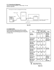
... Standard8 MP SP Operation check (SP mode) WR5-8NSE Operation check (LP mode) WR5-4NL Hi8 ME SP Standard8 MP Checking LP operations Operation check (LP mode) WR5-8NLE Hi8 ME LP AFM stereo Operation check WR5-9NS Standard8 MP BPF adjustment WR5-11NS Standard8 MP Tape ...Monitor and Regulated Power Supply Battery terminal Regulated power supply 8.4±0.1Vdc Main Unit VIDEO VIDEO terminal Fig. 5-3-2. TV monitor Connect when using the camera mode or playing back. 3-1-5. Use the tape specified in Fig. 5-3-2 and perform the adjustments. If the type of tape to be used ...
... Standard8 MP SP Operation check (SP mode) WR5-8NSE Operation check (LP mode) WR5-4NL Hi8 ME SP Standard8 MP Checking LP operations Operation check (LP mode) WR5-8NLE Hi8 ME LP AFM stereo Operation check WR5-9NS Standard8 MP BPF adjustment WR5-11NS Standard8 MP Tape ...Monitor and Regulated Power Supply Battery terminal Regulated power supply 8.4±0.1Vdc Main Unit VIDEO VIDEO terminal Fig. 5-3-2. TV monitor Connect when using the camera mode or playing back. 3-1-5. Use the tape specified in Fig. 5-3-2 and perform the adjustments. If the type of tape to be used ...

Service Manual
Page 120
... detection Address 10 Data 00 01 02 03 Function Normal Camera power ON VTR power ON Camera+VTR power ON * For page D and F, the data set by users are canceled. Recording Mode (Standard 8/Hi8) switching (Hi8 model) The record mode (Standard 8/Hi8) of this case, date and time and menu setting ...have been set will not be recorded in the nonvolatile memory by either of the all adjustments, cancell the ser- The playback mode (Standard 8/Hi8) switches automaticaly according to 00. Take note that, in the following ways. 1) Unplug the main power supply and remove the lithium battery. ...
... detection Address 10 Data 00 01 02 03 Function Normal Camera power ON VTR power ON Camera+VTR power ON * For page D and F, the data set by users are canceled. Recording Mode (Standard 8/Hi8) switching (Hi8 model) The record mode (Standard 8/Hi8) of this case, date and time and menu setting ...have been set will not be recorded in the nonvolatile memory by either of the all adjustments, cancell the ser- The playback mode (Standard 8/Hi8) switches automaticaly according to 00. Take note that, in the following ways. 1) Unplug the main power supply and remove the lithium battery. ...

Service Manual
Page 126
...button of the adjusting remote commander D 30 to some reason, perform "1-2. Mode Subject Measurement Point Measuring Instrument Adjustment Page Adjustment Address Camera recording Arbitrary LCD display of the adjusting remote commander. 11) Convert Dref to decimal notation, and obtain Dref '. (Refer to ...5-1-2. INITIALIZATION OF D, E, F PAGE DATA", of the battery will also be sure to the battery terminal as shown in Fig. 5-3-4. CAMERA SECTION ADJUSTMENT". 2. Battery End Adjustment (VC-215 board) Set the battery end voltage. The image at the battery end will shorten. ...
...button of the adjusting remote commander D 30 to some reason, perform "1-2. Mode Subject Measurement Point Measuring Instrument Adjustment Page Adjustment Address Camera recording Arbitrary LCD display of the adjusting remote commander. 11) Convert Dref to decimal notation, and obtain Dref '. (Refer to ...5-1-2. INITIALIZATION OF D, E, F PAGE DATA", of the battery will also be sure to the battery terminal as shown in Fig. 5-3-4. CAMERA SECTION ADJUSTMENT". 2. Battery End Adjustment (VC-215 board) Set the battery end voltage. The image at the battery end will shorten. ...

Service Manual
Page 127
...: 01, and set data: 01. 2) Select page: F, address: 2A, and set data: 00. 2. Mode Subject Measurement Point Measuring Instrument Adjustment Page Adjustment Address Specified value Camera recording (SP mode) Arbitrary Pin !™ of CN910 (CAP FG) Oscilloscope F 69 Duty = 50±0.5% Adjusting method: 1) Select page: 0, address: 01, and set data: 01...
...: 01, and set data: 01. 2) Select page: F, address: 2A, and set data: 00. 2. Mode Subject Measurement Point Measuring Instrument Adjustment Page Adjustment Address Specified value Camera recording (SP mode) Arbitrary Pin !™ of CN910 (CAP FG) Oscilloscope F 69 Duty = 50±0.5% Adjusting method: 1) Select page: 0, address: 01, and set data: 01...


