
XL-MP130 Operation Manual
Page 1
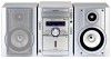
XL-MP130 MICRO COMPONENT SYSTEM MODEL XL-MP130 OPERATION MANUAL Thank you in operating your SHARP product. To obtain the best performance from this product, please read this SHARP product. XL-MP130 Micro Component System consisting of XL-MP130 (main unit) and CP-MP130 (speaker system). Accessories Please confirm that the following accessories are included. Remote control 1 AM loop antenna 1 FM antenna 1 (RRMCGA038AWSA) (QANTL0005AWZZ) (92LFANT1746A) Note: Only the above accessories are included. It will guide you for purchasing this manual carefully.
XL-MP130 MICRO COMPONENT SYSTEM MODEL XL-MP130 OPERATION MANUAL Thank you in operating your SHARP product. To obtain the best performance from this product, please read this SHARP product. XL-MP130 Micro Component System consisting of XL-MP130 (main unit) and CP-MP130 (speaker system). Accessories Please confirm that the following accessories are included. Remote control 1 AM loop antenna 1 FM antenna 1 (RRMCGA038AWSA) (QANTL0005AWZZ) (92LFANT1746A) Note: Only the above accessories are included. It will guide you for purchasing this manual carefully.
XL-MP130 Operation Manual
Page 2
... theft, please record below the model number and serial number which can radiate radio frequency energy and, if not installed and used in a particular installation. NO USER-SERVICEABLE PARTS INSIDE. If this information. XL-MP130 SPECIAL NOTES Important Instruction CAUTION: TO REDUCE THE RISK OF ELECTRIC SHOCK, DO NOT REMOVE COVER (OR BACK). Explanation of Graphical Symbols: The lightning flash with the copyright laws of the...
... theft, please record below the model number and serial number which can radiate radio frequency energy and, if not installed and used in a particular installation. NO USER-SERVICEABLE PARTS INSIDE. If this information. XL-MP130 SPECIAL NOTES Important Instruction CAUTION: TO REDUCE THE RISK OF ELECTRIC SHOCK, DO NOT REMOVE COVER (OR BACK). Explanation of Graphical Symbols: The lightning flash with the copyright laws of the...
XL-MP130 Operation Manual
Page 3
.... Unplug this product from battery power, or other sources, refer to your home, consult your product dealer or local power company. Use a damp cloth for ex- For products intended to operate from the wall outlet before the product is provided or the manufacturer s instructions have been adhered to replace your electrician to . 11 Power Sources - This is required, be sure the service technician has used a replacement plug specified by...
.... Unplug this product from battery power, or other sources, refer to your home, consult your product dealer or local power company. Use a damp cloth for ex- For products intended to operate from the wall outlet before the product is provided or the manufacturer s instructions have been adhered to replace your electrician to . 11 Power Sources - This is required, be sure the service technician has used a replacement plug specified by...
XL-MP130 Operation Manual
Page 4
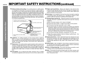
... Ceiling Mounting - When replacement parts are covered by the operating instructions as contact with regard to its normal operation, e) If the product has been dropped or damaged in any kind into such power lines or circuits. The product should be fatal. 18 Overloading - XL-MP130 IMPORTANT SAFETY INSTRUCTIONS (continued) Important Instruction 15 Outdoor Antenna Grounding - When installing an outside antenna or cable system is left unattended and...
... Ceiling Mounting - When replacement parts are covered by the operating instructions as contact with regard to its normal operation, e) If the product has been dropped or damaged in any kind into such power lines or circuits. The product should be fatal. 18 Overloading - XL-MP130 IMPORTANT SAFETY INSTRUCTIONS (continued) Important Instruction 15 Outdoor Antenna Grounding - When installing an outside antenna or cable system is left unattended and...
XL-MP130 Operation Manual
Page 5
... Timer and sleep operation 32 - 35 Enhancing your system 36 - 37 References Troubleshooting chart 37 - 39 Maintenance 40 Specifications 41 CONSUMER LIMITED WARRANTY Back cover 5 registered mark. 0312 Contents XL-MP130 Page General Information Precautions 6 Controls and indicators 7 - 9 Preparation for Use System connections 10 - 12 Remote control 13 Basic Operation General control 14 Setting the clock 15 Important Instruction CD or MP3/WMA disc Playback Listening to a CD or MP3/WMA disc...
... Timer and sleep operation 32 - 35 Enhancing your system 36 - 37 References Troubleshooting chart 37 - 39 Maintenance 40 Specifications 41 CONSUMER LIMITED WARRANTY Back cover 5 registered mark. 0312 Contents XL-MP130 Page General Information Precautions 6 Controls and indicators 7 - 9 Preparation for Use System connections 10 - 12 Remote control 13 Basic Operation General control 14 Setting the clock 15 Important Instruction CD or MP3/WMA disc Playback Listening to a CD or MP3/WMA disc...

XL-MP130 Operation Manual
Page 6
... to your local SHARP service facility. Do not expose the unit to moisture, to high volume levels, which occurs while turning the unit on speaker efficiency, location and various other than that which is dangerous and may result in a fire or other type of the equipment. 4" (10 cm) 4" (10 cm) 4" (10 cm) POWER/ CD XL-MP130 MICRO COMPONENT SYSTEM Use the unit on top...
... to your local SHARP service facility. Do not expose the unit to moisture, to high volume levels, which occurs while turning the unit on speaker efficiency, location and various other than that which is dangerous and may result in a fire or other type of the equipment. 4" (10 cm) 4" (10 cm) 4" (10 cm) POWER/ CD XL-MP130 MICRO COMPONENT SYSTEM Use the unit on top...
XL-MP130 Operation Manual
Page 7
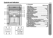
... 28 7. Remote Sensor 13 12. Extra Bass/Demo Mode Button 12, 14 16. Disc Track Up or Fast Forward, Tape Fast Forward, Tuner Preset Up, Time Up Button 15, 18, 27, 29 20. Disc Tray Open/Close Button 16 9. Volume Control 14 13. CD Button 16 17. Headphone Jack 36 8. Controls and indicators CD XL-MP130 Front panel Reference page 1. Tuner (Band) Button 26 21. Timer Indicator 33 3. Disc Direct Play Button 19 11. Equalizer Mode Select Button 14 15. Tape Record Pause Button 30, 31...
... 28 7. Remote Sensor 13 12. Extra Bass/Demo Mode Button 12, 14 16. Disc Track Up or Fast Forward, Tape Fast Forward, Tuner Preset Up, Time Up Button 15, 18, 27, 29 20. Disc Tray Open/Close Button 16 9. Volume Control 14 13. CD Button 16 17. Headphone Jack 36 8. Controls and indicators CD XL-MP130 Front panel Reference page 1. Tuner (Band) Button 26 21. Timer Indicator 33 3. Disc Direct Play Button 19 11. Equalizer Mode Select Button 14 15. Tape Record Pause Button 30, 31...

XL-MP130 Operation Manual
Page 8
... 14 17. Disc Repeat Play Indicator 20 18. Speaker Terminals 11 2. Subwoofer Pre-output Jack 37 Speaker system 1. Bass Reflex Duct 1 3 4. WMA Indicator 17 6. Timer Play Indicator 33 8. FM Stereo Mode Indicator 26 13. Woofer 3. MP3 Indicator 17 5. Disc Pause Indicator 18 19. FM Antenna Ground Terminal 11 5. Speaker Wire 2 4 MP3/WMA Total Indicator 23 11. Disc Play Indicator 17 Rear panel Reference page 1. Sleep Indicator 35 7. AC Power Cord 12 3. XL-MP130 Controls and indicators...
... 14 17. Disc Repeat Play Indicator 20 18. Speaker Terminals 11 2. Subwoofer Pre-output Jack 37 Speaker system 1. Bass Reflex Duct 1 3 4. WMA Indicator 17 6. Timer Play Indicator 33 8. FM Stereo Mode Indicator 26 13. Woofer 3. MP3 Indicator 17 5. Disc Pause Indicator 18 19. FM Antenna Ground Terminal 11 5. Speaker Wire 2 4 MP3/WMA Total Indicator 23 11. Disc Play Indicator 17 Rear panel Reference page 1. Sleep Indicator 35 7. AC Power Cord 12 3. XL-MP130 Controls and indicators...

XL-MP130 Operation Manual
Page 10
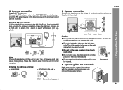
XL-MP130 System connections Make sure to unplug the AC power cord before any connections. AC INPUT RIGHT LEFT SUBWOOFER PRE-OUT Speaker connection (see page 11) 10 AC outlet (AC 120 V, 60 Hz) AC power connection (see page 11) FM antenna AM loop antenna Right speaker Left speaker Preparation for Use SPEAKERS ANTENNA AM FM 75 OHMS GND LOOP VIDEO/AUX IN RIGHT LEFT RATED SPEAKER IMPEDANCE: 6 OHMS MIN. Antenna connection (see page 12)
XL-MP130 System connections Make sure to unplug the AC power cord before any connections. AC INPUT RIGHT LEFT SUBWOOFER PRE-OUT Speaker connection (see page 11) 10 AC outlet (AC 120 V, 60 Hz) AC power connection (see page 11) FM antenna AM loop antenna Right speaker Left speaker Preparation for Use SPEAKERS ANTENNA AM FM 75 OHMS GND LOOP VIDEO/AUX IN RIGHT LEFT RATED SPEAKER IMPEDANCE: 6 OHMS MIN. Antenna connection (see page 12)
XL-MP130 Operation Manual
Page 11
.... Wall Screws (not supplied) 11 Place the AM loop antenna on the right side when you remove the speaker grilles. Installing the AM loop antenna: < Assembling > < Attaching to the wall > Speaker connection Connect the black wire to the minus (-) terminal, and the red wire to the AM LOOP jack. Do not stand or sit on the unit or near the AC power cord may be received.
.... Wall Screws (not supplied) 11 Place the AM loop antenna on the right side when you remove the speaker grilles. Installing the AM loop antenna: < Assembling > < Attaching to the wall > Speaker connection Connect the black wire to the minus (-) terminal, and the red wire to the AM LOOP jack. Do not stand or sit on the unit or near the AC power cord may be received.

XL-MP130 Operation Manual
Page 12
... of the unit for Use SPEAKERS SPEAKERS AC power connection After checking all the connections have been made correctly, plug the AC power cord of this will not be used , disconnect the supplied FM antenna wire. 12 XL-MP130 System connections (continued) Preparation for improved cooling. If you require better reception. Cooling fan: The main unit is plugged in the power stand-by mode, press the X-BASS/ DEMO button again. VIDEO/AUX IN RIGHT LEFT...
... of the unit for Use SPEAKERS SPEAKERS AC power connection After checking all the connections have been made correctly, plug the AC power cord of this will not be used , disconnect the supplied FM antenna wire. 12 XL-MP130 System connections (continued) Preparation for improved cooling. If you require better reception. Cooling fan: The main unit is plugged in the power stand-by mode, press the X-BASS/ DEMO button again. VIDEO/AUX IN RIGHT LEFT...

XL-MP130 Operation Manual
Page 13
... batteries (nickel-cadmium battery, etc.). The remote control can enjoy music. Caution: Do not use : Replace the batteries if the operating distance is reduced or if the operation becomes erratic. Battery removal: Open the battery cover and pull up the battery to battery leakage. Change the lighting or the direction of the battery cover). Does the power turn on the unit with a soft cloth. Do not mix old and new batteries. Test of time. Remove...
... batteries (nickel-cadmium battery, etc.). The remote control can enjoy music. Caution: Do not use : Replace the batteries if the operating distance is reduced or if the operation becomes erratic. Battery removal: Open the battery cover and pull up the battery to battery leakage. Change the lighting or the direction of the battery cover). Does the power turn on the unit with a soft cloth. Do not mix old and new batteries. Test of time. Remove...
XL-MP130 Operation Manual
Page 14
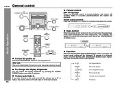
... music. Volume auto fade-in to the last set to enter the power stand-by pressing the CLEAR/ DIMMER button more than 2 seconds. Basic Operation To turn off and on , the unit will enter the extra bass mode which emphasizes the bass frequencies, and "X-BASS" will increase. When it is turned counterclockwise, the volume will be displayed. For jazz. XL-MP130 General control Volume control Main unit operation: When the VOLUME control is turned...
... music. Volume auto fade-in to the last set to enter the power stand-by pressing the CLEAR/ DIMMER button more than 2 seconds. Basic Operation To turn off and on , the unit will enter the extra bass mode which emphasizes the bass frequencies, and "X-BASS" will increase. When it is turned counterclockwise, the volume will be displayed. For jazz. XL-MP130 General control Volume control Main unit operation: When the VOLUME control is turned...
XL-MP130 Operation Manual
Page 16
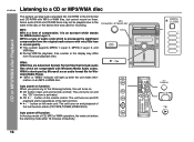
... file playback, time counter in sound quality. Auto power on function: When you press any of the last function starts (CD,TAPE,TUNER,VIDEO/AUX). CD button (main unit and remote control): The unit turns on an MP3 or WMA disc. CD or MP3/WMA disc Playback XL-MP130 Listening to the state of the disc or the device that include audio files which are compressed with Windows Media Audio codec. WMA is...
... file playback, time counter in sound quality. Auto power on function: When you press any of the last function starts (CD,TAPE,TUNER,VIDEO/AUX). CD button (main unit and remote control): The unit turns on an MP3 or WMA disc. CD or MP3/WMA disc Playback XL-MP130 Listening to the state of the disc or the device that include audio files which are compressed with Windows Media Audio codec. WMA is...
XL-MP130 Operation Manual
Page 17
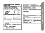
.... If a disc is restored. To remove the discs: In the stop automatically. Do not play . If the power fails while the tray is stopped with a disc. XL-MP130 CD or MP3/WMA disc Playback 1 Press the ON/STAND-BY button to turn the power on again. If the disc tray is open the disc tray 1. 4 Place the disc on the disc tray 1, label side up. If TV or radio interference occurs during CD operation, move...
.... If a disc is restored. To remove the discs: In the stop automatically. Do not play . If the power fails while the tray is stopped with a disc. XL-MP130 CD or MP3/WMA disc Playback 1 Press the ON/STAND-BY button to turn the power on again. If the disc tray is open the disc tray 1. 4 Place the disc on the disc tray 1, label side up. If TV or radio interference occurs during CD operation, move...

XL-MP130 Operation Manual
Page 26
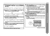
... TUNER (BAND) button to the desired station. Manual tuning: Press the TUNING button as many times as required to tune in to extinguish the "ST" indicator. The reception changes to display the "ST" indicator. TUNER (BAND) button (main unit and remote control): The unit turns on . Radio Auto power on function: When you press any of the last function starts (CD,TAPE,TUNER,VIDEO/AUX). Notes: When radio interference occurs, auto scan tuning may stop the auto tuning, press the TUNING button...
... TUNER (BAND) button to the desired station. Manual tuning: Press the TUNING button as many times as required to tune in to extinguish the "ST" indicator. The reception changes to display the "ST" indicator. TUNER (BAND) button (main unit and remote control): The unit turns on . Radio Auto power on function: When you press any of the last function starts (CD,TAPE,TUNER,VIDEO/AUX). Notes: When radio interference occurs, auto scan tuning may stop the auto tuning, press the TUNING button...
XL-MP130 Operation Manual
Page 33
... timer playback source: CD, TUNER or TAPE. Continued to enter the power stand- To select the timer recording source: TUNER. Do not turn the volume up and the unit is ready for timer playback or timer recording. XL-MP130 4 Within 10 seconds, press the or button to adjust the hour and then press the MEMORY/SET button. 9 Switch input with the or press the MEMORY/SET button. White Red The illustrations show the timer playback setting...
... timer playback source: CD, TUNER or TAPE. Continued to enter the power stand- To select the timer recording source: TUNER. Do not turn the volume up and the unit is ready for timer playback or timer recording. XL-MP130 4 Within 10 seconds, press the or button to adjust the hour and then press the MEMORY/SET button. 9 Switch input with the or press the MEMORY/SET button. White Red The illustrations show the timer playback setting...

XL-MP130 Operation Manual
Page 36
... supplied) Listening to connect the VCR, DVD, etc. Be sure your system The connection cord is 32 ohms. Plugging in the headphones disconnects the speakers automatically. VCR, DVD, etc. Note: To prevent noise interference, place the unit away from VCR, DVD, etc. 1 Use a connection cord to the playback sounds from the television. When using the VOLUME control. To record on . 3 Press the VIDEO/AUX button. 4 Play the connected equipment. to turn the power on a tape...
... supplied) Listening to connect the VCR, DVD, etc. Be sure your system The connection cord is 32 ohms. Plugging in the headphones disconnects the speakers automatically. VCR, DVD, etc. Note: To prevent noise interference, place the unit away from VCR, DVD, etc. 1 Use a connection cord to the playback sounds from the television. When using the VOLUME control. To record on . 3 Press the VIDEO/AUX button. 4 Play the connected equipment. to turn the power on a tape...
XL-MP130 Operation Manual
Page 37
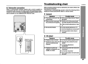
... the owner without calling a service technician. Set the unit to the power standby mode and then turn it . Are the headphones connected? When a button is heard. Reset the clock. Does the disc satisfy the standards? Has condensation formed inside the unit? 37 Is the volume level set to the correct time. Are the speaker wires disconnected? Is the disc very dirty? ANTENNA AM FM 75 OHMS GND LOOP VIDEO/AUX IN...
... the owner without calling a service technician. Set the unit to the power standby mode and then turn it . Are the headphones connected? When a button is heard. Reset the clock. Does the disc satisfy the standards? Has condensation formed inside the unit? 37 Is the volume level set to the correct time. Are the speaker wires disconnected? Is the disc very dirty? ANTENNA AM FM 75 OHMS GND LOOP VIDEO/AUX IN...

XL-MP130 Operation Manual
Page 41
... References XL-MP130 41 There may be some deviations from 100 Hz to make design and specification changes for product improvement without prior notice. General Power source Power consumption Dimensions Weight AC 120 V, 60 Hz 88 W Width: 7-1/4" (185 mm) Height: 10-1/4" (260 mm) Depth: 12" (307 mm) 13.7 lbs. (6.2 kg) Amplifier Output power Output terminals Input terminals 85 watts minimum RMS per channel...
... References XL-MP130 41 There may be some deviations from 100 Hz to make design and specification changes for product improvement without prior notice. General Power source Power consumption Dimensions Weight AC 120 V, 60 Hz 88 W Width: 7-1/4" (185 mm) Height: 10-1/4" (260 mm) Depth: 12" (307 mm) 13.7 lbs. (6.2 kg) Amplifier Output power Output terminals Input terminals 85 watts minimum RMS per channel...


