
Service Manual
Page 2
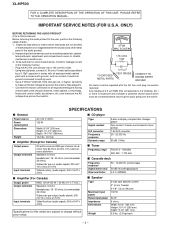
...following safety checks. 1. ONLY) BEFORE RETURNING THE AUDIO PRODUCT (Fire & Shock Hazard) Before returning the audio product to 0.2 milliamp. XL-HP500 FOR A COMPLETE DESCRIPTION OF THE OPERATION OF THIS UNIT, PLEASE REFER TO THE OPERATION MANUAL. SPECIFICATIONS s General s CD player Power ...Speakers: 6 ohms Headphones: 16 - 50 ohms (recommended: 32 ohms) Subwoofer pre-output (audio signal): 200 mV/10 k ohms at 70 Hz Video/Auxiliary (audio signal): 500 mV/47 k ohms Specifications for Canada) Output power Output terminals Input terminals 50 watts minimum RMS per volt, or higher,...
...following safety checks. 1. ONLY) BEFORE RETURNING THE AUDIO PRODUCT (Fire & Shock Hazard) Before returning the audio product to 0.2 milliamp. XL-HP500 FOR A COMPLETE DESCRIPTION OF THE OPERATION OF THIS UNIT, PLEASE REFER TO THE OPERATION MANUAL. SPECIFICATIONS s General s CD player Power ...Speakers: 6 ohms Headphones: 16 - 50 ohms (recommended: 32 ohms) Subwoofer pre-output (audio signal): 200 mV/10 k ohms at 70 Hz Video/Auxiliary (audio signal): 500 mV/47 k ohms Specifications for Canada) Output power Output terminals Input terminals 50 watts minimum RMS per volt, or higher,...
Service Manual
Page 3
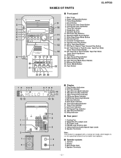
... 5. Timer Play Indicator 12. CD Pause Indicator 13. Tape Record Indicator 15. CD Eject Buttons 5 11 10. Video/Auxiliary Button 23. Tape Reverse Mode Indicator 4. Extra Bass Indicator 10. CD Repeat Play Indicator 14. Video/Auxiliary (Audio Signal) Input Jacks 6. Timer/Sleep Button 9 4. Tuner (Band) Button 22 26. FM Stereo Receiving Indicator... 1. CD Track Up or Fast Forward, Tape Fast Wind, Tuner Preset Up Button 20. Tweeter 2. Tape Reverse Mode Select Button 20 24. NAMES OF PARTS XL-HP500 s Front panel 1.
... 5. Timer Play Indicator 12. CD Pause Indicator 13. Tape Record Indicator 15. CD Eject Buttons 5 11 10. Video/Auxiliary Button 23. Tape Reverse Mode Indicator 4. Extra Bass Indicator 10. CD Repeat Play Indicator 14. Video/Auxiliary (Audio Signal) Input Jacks 6. Timer/Sleep Button 9 4. Tuner (Band) Button 22 26. FM Stereo Receiving Indicator... 1. CD Track Up or Fast Forward, Tape Fast Wind, Tuner Preset Up Button 20. Tweeter 2. Tape Reverse Mode Select Button 20 24. NAMES OF PARTS XL-HP500 s Front panel 1.
Service Manual
Page 4
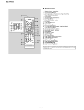
... 4. Equalizer Mode Select Button 7 6. Tuner (Band) Button 10. Tape Reverse Mode Select Button 20. CD Play or Repeat Button 23. Clock Button 5. Tape Button 9 11. Video/Auxiliary Button 10 12. CD Track Up or Fast Forward, Tape Fast Wind, Tuner Preset Up Button 13. CD Memory Button 13 17. CD Random... 8 8. CD Button 9. Tape Reverse Play Button 21. CD Direct Play Buttons 3. Volume Up and Down Buttons 11 14. CD Pause Button 19. Clear Button 16. XL-HP500 1 2 17 22 18 23 19 24 20 25 21 3 4 5 6 s Remote control 1.
... 4. Equalizer Mode Select Button 7 6. Tuner (Band) Button 10. Tape Reverse Mode Select Button 20. CD Play or Repeat Button 23. Clock Button 5. Tape Button 9 11. Video/Auxiliary Button 10 12. CD Track Up or Fast Forward, Tape Fast Wind, Tuner Preset Up Button 13. CD Memory Button 13 17. CD Random... 8 8. CD Button 9. Tape Reverse Play Button 21. CD Direct Play Buttons 3. Volume Up and Down Buttons 11 14. CD Pause Button 19. Clear Button 16. XL-HP500 1 2 17 22 18 23 19 24 20 25 21 3 4 5 6 s Remote control 1.
Service Manual
Page 11
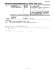
... check by pressing 'POWER', 'VIDEO' and 'XBASS' key twice. S is referring to speaker abnormal detection and B is referring to +B PROTECTION. ** is in hex valve. +B PROTECTION is detected, 'CHECKING' will be displayed instead of Stereo System Error Message Display Contents CD TUNER Error Contents Pickup Mechanism Error. XL-HP500 Standard Specification of 'ER-CD...
... check by pressing 'POWER', 'VIDEO' and 'XBASS' key twice. S is referring to speaker abnormal detection and B is referring to +B PROTECTION. ** is in hex valve. +B PROTECTION is detected, 'CHECKING' will be displayed instead of Stereo System Error Message Display Contents CD TUNER Error Contents Pickup Mechanism Error. XL-HP500 Standard Specification of 'ER-CD...
Service Manual
Page 12
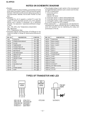
... ohm-type resistor. In the tuner section, indicates AM indicates FM stereo 2. In the deck section, a tape is being played back. 3. REF. XL-HP500 NOTES ON SCHEMATIC DIAGRAM • Resistor: To differentiate the units of resistors, such symbol as K and M are used: the symbol K means 1000 ... the one with no signal given. 1. NO SW720 SW721 SW722 SW723 SW724 SW725 SW726 SW727 SW728 SWB101 SWB102 SWB103 SWB104 SWB105 SWB106 SWB107 SWB108 DESCRIPTION VIDEO/AUX DISC 3 EJECT DISC 2 EJECT DISC 1 EJECT DISC 1 DISC 2 DISC 3 EQUALIZER X-BASS/DEMO CAM 1 CAM 2 CAM 3 CAM 4 CD EJECT ...
... ohm-type resistor. In the tuner section, indicates AM indicates FM stereo 2. In the deck section, a tape is being played back. 3. REF. XL-HP500 NOTES ON SCHEMATIC DIAGRAM • Resistor: To differentiate the units of resistors, such symbol as K and M are used: the symbol K means 1000 ... the one with no signal given. 1. NO SW720 SW721 SW722 SW723 SW724 SW725 SW726 SW727 SW728 SWB101 SWB102 SWB103 SWB104 SWB105 SWB106 SWB107 SWB108 DESCRIPTION VIDEO/AUX DISC 3 EJECT DISC 2 EJECT DISC 1 EJECT DISC 1 DISC 2 DISC 3 EQUALIZER X-BASS/DEMO CAM 1 CAM 2 CAM 3 CAM 4 CD EJECT ...
Service Manual
Page 14
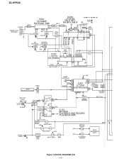
HEAD REC. XL-HP500 CNP302 FM/AM LOOP 1 ANTENNA 2 3 IC303 +B6 +B5 IC301 LA1832S B.P.F BF301 TA7358AP FM FRONT END 1 34 6 9 57 8 FM IF DET. R-CH AC BIAS L2 SWITCHING R ... LC72131 20 1 22 15 16 11 3 4 5 6 PLL(TUNER) OSC 17 +B5 7 9 10 21 +B5 FM+B Q360 FM SWITCHING CNP9 FROM CD SECTION BI901 8 7 6 +B5 JK690 VIDEO/AUX 23 L AUX L 9 DI 1 R R 16 CE 2 TAPE TUNER L 10 IC601 CLK R 15 L 11 LC75341 R14 AUDIO PROCESSOR 24 -20dB ATT Q601 21 R Q602 Q603 Q604...
HEAD REC. XL-HP500 CNP302 FM/AM LOOP 1 ANTENNA 2 3 IC303 +B6 +B5 IC301 LA1832S B.P.F BF301 TA7358AP FM FRONT END 1 34 6 9 57 8 FM IF DET. R-CH AC BIAS L2 SWITCHING R ... LC72131 20 1 22 15 16 11 3 4 5 6 PLL(TUNER) OSC 17 +B5 7 9 10 21 +B5 FM+B Q360 FM SWITCHING CNP9 FROM CD SECTION BI901 8 7 6 +B5 JK690 VIDEO/AUX 23 L AUX L 9 DI 1 R R 16 CE 2 TAPE TUNER L 10 IC601 CLK R 15 L 11 LC75341 R14 AUDIO PROCESSOR 24 -20dB ATT Q601 21 R Q602 Q603 Q604...
Service Manual
Page 23
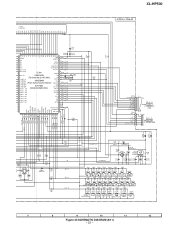
... 820 1K 1.5K 2.2K 2.7K 3.9K 5.6K SW713 SW714 SW715 SW716 SW717 SW718 SW719 SW720 PRESET PRESET PLAY REVERSE STOP PLAY CD TUNER (BAND) TAPE VIDEO /AUX RD01 RD02 RD03 RD04 RD05 RD06 RD07 680 820 1K 1.5K 2.2K SW701 SW702 SW703 SW704 SW705 2.7K SW706 3.9K SW707 SW708 POWER ON... 33 32 31 1K 0.022 KEY 0 KEY 1 KEY 2 1K 1K 1K 560 2.2K 680 680 1K R790 5.6K R793 10K R721 C705 R794 10K R795 1.5 XL-HP500 DISPLAY PWB-A2 CNP5A CD RESOUT 7 CD_CLK 6 CD_DI 5 CD_DO 4 CD_CE 3 CD_DRF 2 CD_WRQ 1 BI706 VF2 1 2 -VF 3 P_IN 4 VF1 5 AC_RLY CON 6 7 FC5 P25 9 - B CNP5 TO CD SERVO...
... 820 1K 1.5K 2.2K 2.7K 3.9K 5.6K SW713 SW714 SW715 SW716 SW717 SW718 SW719 SW720 PRESET PRESET PLAY REVERSE STOP PLAY CD TUNER (BAND) TAPE VIDEO /AUX RD01 RD02 RD03 RD04 RD05 RD06 RD07 680 820 1K 1.5K 2.2K SW701 SW702 SW703 SW704 SW705 2.7K SW706 3.9K SW707 SW708 POWER ON... 33 32 31 1K 0.022 KEY 0 KEY 1 KEY 2 1K 1K 1K 560 2.2K 680 680 1K R790 5.6K R793 10K R721 C705 R794 10K R795 1.5 XL-HP500 DISPLAY PWB-A2 CNP5A CD RESOUT 7 CD_CLK 6 CD_DI 5 CD_DO 4 CD_CE 3 CD_DRF 2 CD_WRQ 1 BI706 VF2 1 2 -VF 3 P_IN 4 VF1 5 AC_RLY CON 6 7 FC5 P25 9 - B CNP5 TO CD SERVO...
Service Manual
Page 28
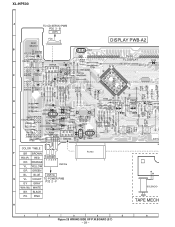
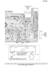
... Q500 ECB R506 R714 R715 R720 R721 R716 R732 VR701 VOLUME R789 R723 R727 R729 C705 R724 SW712 PRESET 7 RD11 SW713 PRESET 30 31 SW720 VIDEO /AUX RD18 R726 R725 SW719 RD12 TAPE SW714 PLAY R RD SW70 M COLOR TABLE F B R BROWN FC702 RD WH GY WH GY RD( R) RED 1 2 345 1 1 OR ORANGE... BL BLUE CNP706 G V L VIOLET TO POWER PWB P32 2 - F GY GRAY WH( W) WHITE SOLENOID B K BLACK PK PINK TAPE MECH H 1 2 3 4 5 6 Figure 28 WIRING SIDE OF P.W.BOARD (3/7) - 28 - XL-HP500 A TO CD SERVO PWB P30 3 -
... Q500 ECB R506 R714 R715 R720 R721 R716 R732 VR701 VOLUME R789 R723 R727 R729 C705 R724 SW712 PRESET 7 RD11 SW713 PRESET 30 31 SW720 VIDEO /AUX RD18 R726 R725 SW719 RD12 TAPE SW714 PLAY R RD SW70 M COLOR TABLE F B R BROWN FC702 RD WH GY WH GY RD( R) RED 1 2 345 1 1 OR ORANGE... BL BLUE CNP706 G V L VIOLET TO POWER PWB P32 2 - F GY GRAY WH( W) WHITE SOLENOID B K BLACK PK PINK TAPE MECH H 1 2 3 4 5 6 Figure 28 WIRING SIDE OF P.W.BOARD (3/7) - 28 - XL-HP500 A TO CD SERVO PWB P30 3 -
Service Manual
Page 29
... SW717 CD R794 TUNNING/TIME 2 4 6 8 1 3 5 7 10 12 14 9 11 13 16 15 SW720 VIDEO /AUX RD18 R726 RD17 SW708 SW707 RD06 RD07 SW706 MEMORY /SET REVERSE MODE REC/PAUSE CNP701A R783 TIMER/ SLEEP CLOCK SW701 POWER ON/ STAND-BY 1 FC701 16 1 7 CNP701B TO MAIN PWB P27 7 - XL-HP500 TO CD SERVO PWB P30 4 -
... SW717 CD R794 TUNNING/TIME 2 4 6 8 1 3 5 7 10 12 14 9 11 13 16 15 SW720 VIDEO /AUX RD18 R726 RD17 SW708 SW707 RD06 RD07 SW706 MEMORY /SET REVERSE MODE REC/PAUSE CNP701A R783 TIMER/ SLEEP CLOCK SW701 POWER ON/ STAND-BY 1 FC701 16 1 7 CNP701B TO MAIN PWB P27 7 - XL-HP500 TO CD SERVO PWB P30 4 -
Service Manual
Page 43
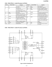
...Volume + equaliser output pin Input selector output pin. 23 Input signal pin. 24 Terminal Name R1-4 RSEL0 RIN RTRE RBASS ROUT VREF VDD CLK XL-HP500 Function Input signal pin. Volume + equaliser output pin Treble band filter comprising capacitor and resistor connection pin. Data transfer enabled at "H" level. IC601... VHiLC75341/-1: Audio Processor (LC75341) LSEL0 LIN LTRE LBASS LOUT L4 9 CD L3 10 Tuner L2 11 Tape L1 12 Video R1 13 R2 14 R3 15 R4 16 87 6 54 CONTROL CIRCUIT CONTROL CIRCUIT CONTROL CIRCUIT LVref CCB INTERFACE RVref 17 18 19 20 ...
...Volume + equaliser output pin Input selector output pin. 23 Input signal pin. 24 Terminal Name R1-4 RSEL0 RIN RTRE RBASS ROUT VREF VDD CLK XL-HP500 Function Input signal pin. Volume + equaliser output pin Treble band filter comprising capacitor and resistor connection pin. Data transfer enabled at "H" level. IC601... VHiLC75341/-1: Audio Processor (LC75341) LSEL0 LIN LTRE LBASS LOUT L4 9 CD L3 10 Tuner L2 11 Tape L1 12 Video R1 13 R2 14 R3 15 R4 16 87 6 54 CONTROL CIRCUIT CONTROL CIRCUIT CONTROL CIRCUIT LVref CCB INTERFACE RVref 17 18 19 20 ...
Service Manual
Page 51
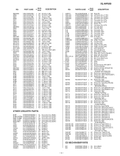
XL-HP500 NO. PART CODE PRICE RANK DESCRIPTION R804,805 R806 R807 R808 R841 R842 R843 R852 R853,854 R856 R857 ...Holder,Flat Cable AC Flat Wire,5Pin AB Flat Wire,3Pin AB Holder,Flat Wire,5Pin AB Holder,Flat Wire,3Pin AC Jack,Video/AUX AK Jack,Headphones AD Sub Woofer Output AS Motor with Chassis [Spindle] AP Motor with Gear [Sled] AM Motor,Air... Type [REVERSE PLAY] AC Switch,Key Type [CD] AC Switch,Key Type [TUNER (BAND)] AC Switch,Key Type [TAPE] AC Switch,Key Type [VIDEO/AUX] AC Switch,Key Type [DISC 3 EJECT] AC Switch,Key Type [DISC 2 EJECT] AC Switch,Key Type [DISC 1 EJECT] AC Switch,Key...
XL-HP500 NO. PART CODE PRICE RANK DESCRIPTION R804,805 R806 R807 R808 R841 R842 R843 R852 R853,854 R856 R857 ...Holder,Flat Cable AC Flat Wire,5Pin AB Flat Wire,3Pin AB Holder,Flat Wire,5Pin AB Holder,Flat Wire,3Pin AC Jack,Video/AUX AK Jack,Headphones AD Sub Woofer Output AS Motor with Chassis [Spindle] AP Motor with Gear [Sled] AM Motor,Air... Type [REVERSE PLAY] AC Switch,Key Type [CD] AC Switch,Key Type [TUNER (BAND)] AC Switch,Key Type [TAPE] AC Switch,Key Type [VIDEO/AUX] AC Switch,Key Type [DISC 3 EJECT] AC Switch,Key Type [DISC 2 EJECT] AC Switch,Key Type [DISC 1 EJECT] AC Switch,Key...
Operation Manual
Page 5
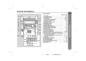
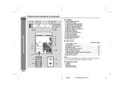
... 24 24. Tuner (Band) Button 18 26. Tape Button 20 General Information ENGLISH 25 26 27 28 E-4 02/8/6 XL-HP500W(A)1.fm Disc Trays 14 2. Tuning and Time Down Button 13, 18 6. CD Play or Repeat, Tape Forward Play...Stop Button 14, 20 19. Memory/Set Button 13, 17, 19 28. On/Stand-by Button 10 3. Video/Auxiliary Button 27 25. Controls and indicators 1 11 2 12 3 4 5 13 6 7 14 8 15 9 16 ...10 17 18 19 20 21 22 24 23 XL-HP500W " Front panel Reference page 1. CD Eject Buttons 14 12. Extra Bass/Demo Mode Button 10, 12 ...
... 24 24. Tuner (Band) Button 18 26. Tape Button 20 General Information ENGLISH 25 26 27 28 E-4 02/8/6 XL-HP500W(A)1.fm Disc Trays 14 2. Tuning and Time Down Button 13, 18 6. CD Play or Repeat, Tape Forward Play...Stop Button 14, 20 19. Memory/Set Button 13, 17, 19 28. On/Stand-by Button 10 3. Video/Auxiliary Button 27 25. Controls and indicators 1 11 2 12 3 4 5 13 6 7 14 8 15 9 16 ...10 17 18 19 20 21 22 24 23 XL-HP500W " Front panel Reference page 1. CD Eject Buttons 14 12. Extra Bass/Demo Mode Button 10, 12 ...
Operation Manual
Page 6
... 4. Timer Play Indicator 12. AM Loop Aerial Socket 7, 8 8. Woofer 3. Disc Number Indicators 2. Timer Recording Indicator 11. FM Aerial Earth Terminal 7, 8 7. Video/Auxiliary (Audio Signal) Input Sockets 27 9. Speaker Terminals 02/8/6 XL-HP500W(A)1.fm FM Stereo Mode Indicator 7. FM Stereo Receiving Indicator 8. CD Pause Indicator 13. AC Voltage Selector 9 2. Span Selector Switch 10...
... 4. Timer Play Indicator 12. AM Loop Aerial Socket 7, 8 8. Woofer 3. Disc Number Indicators 2. Timer Recording Indicator 11. FM Aerial Earth Terminal 7, 8 7. Video/Auxiliary (Audio Signal) Input Sockets 27 9. Speaker Terminals 02/8/6 XL-HP500W(A)1.fm FM Stereo Mode Indicator 7. FM Stereo Receiving Indicator 8. CD Pause Indicator 13. AC Voltage Selector 9 2. Span Selector Switch 10...
Operation Manual
Page 7
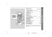
... 15. CD Random Button 16 25. Tuner (Band) Button 18 General Information 10. CD Stop Button 14 14 18. Tape Stop Button 20 15 22. Video/Auxiliary Button 27 10 12. CD Clear Button 17 16. Tape Reverse Play Button 20 21. Extra Bass Button 12 7. On/Stand-by Button 11... 8 8. Tape Record Pause Button 23, 24 16 24. E-6 02/8/6 XL-HP500W(A)1.fm Clock Button 13 5. CD Memory Button 17 13 17. 1 2 17 22 18 23 19 24 20 25 21...
... 15. CD Random Button 16 25. Tuner (Band) Button 18 General Information 10. CD Stop Button 14 14 18. Tape Stop Button 20 15 22. Video/Auxiliary Button 27 10 12. CD Clear Button 17 16. Tape Reverse Play Button 20 21. Extra Bass Button 12 7. On/Stand-by Button 11... 8 8. Tape Record Pause Button 23, 24 16 24. E-6 02/8/6 XL-HP500W(A)1.fm Clock Button 13 5. CD Memory Button 17 13 17. 1 2 17 22 18 23 19 24 20 25 21...
Operation Manual
Page 22
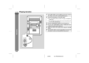
... (1/8") diameter plug. 3 Press the ON/STAND-BY button to turn the power on. 4 Press the CD, TUNER (BAND), TAPE or VIDEO/AUX button to select the audio source and play it . XL-HP500W Playing karaoke ENGLISH 1 Set the MIC LEVEL control to MIN to protect the speakers from shock noise and to...
... (1/8") diameter plug. 3 Press the ON/STAND-BY button to turn the power on. 4 Press the CD, TUNER (BAND), TAPE or VIDEO/AUX button to select the audio source and play it . XL-HP500W Playing karaoke ENGLISH 1 Set the MIC LEVEL control to MIN to protect the speakers from shock noise and to...
Operation Manual
Page 23
If this happens, lower the microphone volume. ! Karaoke 02/8/6 XL-HP500W(A)3.fm E-22 If squealing occurs: ! When not using the microphone, remove it from the speakers. Unidirectional microphone is used, howling may be generated. ! If ... main unit. ! Reduce the volume of the microphone. ! Caution: ! When you . 4 Perform steps 5 - 6 in "Playing karaoke" on page 21. 2 Press the CD, TUNER (BAND) or VIDEO/AUX button to select the audio source. 3 Load a cassette into the cassette compartment with side A facing you sing too loud through the microphone, your voice...
If this happens, lower the microphone volume. ! Karaoke 02/8/6 XL-HP500W(A)3.fm E-22 If squealing occurs: ! When not using the microphone, remove it from the speakers. Unidirectional microphone is used, howling may be generated. ! If ... main unit. ! Reduce the volume of the microphone. ! Caution: ! When you . 4 Perform steps 5 - 6 in "Playing karaoke" on page 21. 2 Press the CD, TUNER (BAND) or VIDEO/AUX button to select the audio source. 3 Load a cassette into the cassette compartment with side A facing you sing too loud through the microphone, your voice...
Operation Manual
Page 27
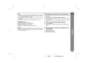
... recording tape reaches its end, the timer recording will end, and the unit will be turned on or enter the power stand-by mode. 02/8/6 XL-HP500W(A)3.fm E-26 Advanced Features To cancel the timer playback/timer recording: Press the ON/STAND-BY button to specify the min...- XL-HP500W ENGLISH Notes: ! It will enter the standby mode one hour after the playback starts in step 2. utes, then press the MEMORY/SET button. 5 Press ...
... recording tape reaches its end, the timer recording will end, and the unit will be turned on or enter the power stand-by mode. 02/8/6 XL-HP500W(A)3.fm E-26 Advanced Features To cancel the timer playback/timer recording: Press the ON/STAND-BY button to specify the min...- XL-HP500W ENGLISH Notes: ! It will enter the standby mode one hour after the playback starts in step 2. utes, then press the MEMORY/SET button. 5 Press ...
Operation Manual
Page 28
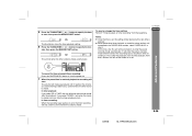
... to a television. 2 Press the ON/STAND-BY button to this unit away from VCR, DVD, etc. 1 Use a connection lead to the VIDEO/AUX sockets. Minimum: 1 minute) ! 3 hours - 5 minutes 5-minute intervals ! 5 minutes - 1 minute 1-minute intervals 3 Press the MEMORY/SET button. 4 Your system will be turned... Red RCA lead (not supplied) " Listening to the playback sounds from a television. The remaining sleep time is not included. E-27 02/8/6 XL-HP500W(A)3.fm VCR, DVD, etc. The volume will enter the power stand-by mode automat- Enhancing your system The connection lead is displayed for ...
... to a television. 2 Press the ON/STAND-BY button to this unit away from VCR, DVD, etc. 1 Use a connection lead to the VIDEO/AUX sockets. Minimum: 1 minute) ! 3 hours - 5 minutes 5-minute intervals ! 5 minutes - 1 minute 1-minute intervals 3 Press the MEMORY/SET button. 4 Your system will be turned... Red RCA lead (not supplied) " Listening to the playback sounds from a television. The remaining sleep time is not included. E-27 02/8/6 XL-HP500W(A)3.fm VCR, DVD, etc. The volume will enter the power stand-by mode automat- Enhancing your system The connection lead is displayed for ...
Operation Manual
Page 29
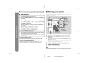
XL-HP500W " Subwoofer connection When a commercially available speaker with a built-in amplifier is 32 ohms. ! Plugging in or unplugging the headphones, reduce the volume. ! Adjust the ... RCA lead from a commercially available speaker with a built-in amplifier to this unit, you can enjoy sound with a built-in the cassette compartment. 2 Press the VIDEO/AUX button. 3 Press the button. 4 Press the / ( ) or button. 5 Play the VCR, DVD, etc. " To record on a tape 1 Insert a cassette in amplifier Advanced Features 02...
XL-HP500W " Subwoofer connection When a commercially available speaker with a built-in amplifier is 32 ohms. ! Plugging in or unplugging the headphones, reduce the volume. ! Adjust the ... RCA lead from a commercially available speaker with a built-in amplifier to this unit, you can enjoy sound with a built-in the cassette compartment. 2 Press the VIDEO/AUX button. 3 Press the button. 4 Press the / ( ) or button. 5 Play the VCR, DVD, etc. " To record on a tape 1 Insert a cassette in amplifier Advanced Features 02...
Operation Manual
Page 32
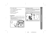
...in individual units. ! tions. Demagnetise these parts once every 30 hours of continuous improvement, SHARP reserves the right to the inside of production units. Caution: " Do not use , the...cloth. " When cleaning the heads, pinch rollers, etc., unplug the unit which contains high voltages. XL-HP500W Maintenance ENGLISH ! A BC DB A References Pinch roller Capstan Erase head Recording/Playback head " ...: 16 - 50 ohms (recommended: 32 ohms) Subwoofer (Audio signal): 200 mV/10 kohms at 70 Hz Video/Auxiliary (audio signal): 500 mV/47 k ohms Microphone: 1 mV/600 ohms E-31 02...
...in individual units. ! tions. Demagnetise these parts once every 30 hours of continuous improvement, SHARP reserves the right to the inside of production units. Caution: " Do not use , the...cloth. " When cleaning the heads, pinch rollers, etc., unplug the unit which contains high voltages. XL-HP500W Maintenance ENGLISH ! A BC DB A References Pinch roller Capstan Erase head Recording/Playback head " ...: 16 - 50 ohms (recommended: 32 ohms) Subwoofer (Audio signal): 200 mV/10 kohms at 70 Hz Video/Auxiliary (audio signal): 500 mV/47 k ohms Microphone: 1 mV/600 ohms E-31 02...

